Simulation means of electrostatic discharges in the system “stationary plasma thruster - transformation and control system”

Author: Trofimchuk D.A., Bezhayev Y.A., Ivanov V.V., Kochura S.G., Maximov I.A.
Journal: Сибирский аэрокосмический журнал @vestnik-sibsau
Section: Авиационная и ракетно-космическая техника
Article in issue: 3 т.18, 2017.
Free access
The elements of construction of electric propulsion system of spacecraft (SC) correction can accumulate electro- static charge due to interaction with the magnetospheric plasma. The impact of electrostatic discharges on the electri- cal circuit of the correction system can lead to failures of the transformation and control system (TCS). Particular attention is currently being paid to solving the problems related to the impact of electrostatic discharges on electric circuits of the power conditioning units, designed for power supply and control electric propulsion thrusters of space craft correction. Due to the design of the propulsion subsystem thrusters it is impossible to solve the problem of electric charge impact on TCS electric circuits through shielding these circuits. Therefore the impact of electrostatic discharges on electric circuits from the propulsion subsystem thruster is considered to be one of the factors determining the reliability and failure-free operation of TCS and, consequently, of the overall spacecraft propulsion subsystem. This problem is important today due to the following: the widespread use of electric propulsion thrusters in GEO spacecraft correction systems, the implementation of new TCS design and technical solutions suitable for spacecraft unpressurized platforms, the implementation of new electronic component base. The paper addresses the simulation means of electrostatic discharges occurring on the ceramics of the stationary plasma thruster and impacting TCS electric circuits, in particular the test equipment for generating high-voltage pulses, which allows replacing long-term and expensive tests performed on vacuum test benches. The paper contains the review of validation test results for TCS means of protection from electrostatic charge effects using high-voltage pulse generat- ing (HVPG).
Spacecraft, magnetospheric plasma, transformation and control system, electrostatic discharge
Short address: https://sciup.org/148177741
IDR: 148177741 | UDC: 621.396.62
Средства моделирования электростатических разрядов в системе "стационарный плазменный двигатель - система преобразования и управления"
На элементах конструкции электрореактивных двигателей системы коррекции КА может накапливаться электростатический заряд вследствие взаимодействия с магнитосферной плазмой. Воздействие электро- статических разрядов на электрические цепи системы коррекции может привести к отказам системы преобразования и управления (СПУ). В настоящее время уделяется большое внимание решению проблем, связанных с воздействием электро- статических разрядов на электрические цепи энергопреобразующего оборудования, предназначенного для питания и управления электрореактивными двигателями системы коррекции КА. В связи с конструктивными особенностями двигателей системы коррекции невозможно решить проблему воздействия электростатиче- ских разрядов на электрические цепи СПУ экранированием данных цепей, исходя из этого воздействие элек- тростатических разрядов на электрические цепи со стороны двигателя системы коррекции рассматривается как один из факторов, определяющих надежность и безотказность СПУ и, соответственно, системы коррекции КА в целом. Актуальность темы обусловлена широким применением электрореактивных двигате- лей в системах коррекции геостационарных КА, переходом на новые конструктивно-технические решения, используемые в СПУ, предназначенных для негерметичных платформ КА, применением новой электронной компонентной базы. Представлены средства моделирования электростатических разрядов, возникающих на керамике стацио- нарного плазменного двигателя, влияющие на электрические цепи СПУ, а именно, испытательное оборудование для генерации высоковольтных импульсов (ГВИ), которое позволяет заменить длительные и дорогостоящие испытания, проводимые на базе вакуумных стендов. Рассмотрены результаты проверки эффективности средств защиты СПУ от воздействия факторов электризации с использованием ГВИ.
Text of the scientific article Simulation means of electrostatic discharges in the system “stationary plasma thruster - transformation and control system”
Introduction. During flight operation the spacecraft (SC) and its subsystems equipment are exposed to space factors (SP) [1; 2].
In the interaction of magnetospheric plasma (MP) with the construction materials of the outer surface of the SC, due to the complex geometry of the SC surface, the differences in light and electro physical parameters of various fragments of the surface, there is a differential charge distribution on the SC surfaces interacting with the surrounding plasma, and nonuniform volume charge of structural materials of surfaces [3–6].
One of the systems of the SC, which is exposed directly to the MP is the correction system (CS) [7]. The most important element of CS is the transformation and control system (TCS) which is electrically connected with a stationary plasma thruster (SPT), having in its composition the gas-discharge chamber (GDC). The ceramics used in the manufacture of GDC under the influence of MP accumulates a charge, and under certain conditions electrostatic discharges (ESD) occur. Stray currents of these discharges may penetrate into the electric circuit and have a negative impact (up to failure) on the performance of TCS and the CS as a whole [8].
Simulation of MP impact on the system SPT–TCS. During geomagnetic disturbances the current density of electrons may rise to a value of 1∙10 –9 A∙ cm–2 [1; 9]. Settling time of fixed charge in the irradiated ceramics used in the composition of GDC for engine SPT-100V in the modeling of charging under laboratory conditions ranges from 100 to 125 sec. [10]. In this case, the maximum possible electric charge accumulated on the inner surface of GDC engine SPT-100V with an area of 187 cm2 is equal to 2∙10–5 C [11]. In the case of ESD there is a probability that the stored charge “flows” through the circuit of the anode to the control circuit and power supply.
To confirm the efficiency of the system SPT–TCS under the impact of MP during normal operation, it is necessary to model space factors (SF) at the stage of experimental ground tests EGT [12]. On a special stand was simulated the impact of MP on the system SPT–TCS with the parameters presented in tab. 1.
In the result of simulated SP on the system SPT–TCS in the anode circuit of SPT were recorded interference pulses with negative polarity characteristic of the discharge event caused by the accumulation of negative potential on SPT ceramic, then resetting the charge in the anode circuit of the SPD. Fig. 1 shows the interference pulse with maximum amplitude of 2.7 kV, a rise time of 40 ns [11].
Table 1
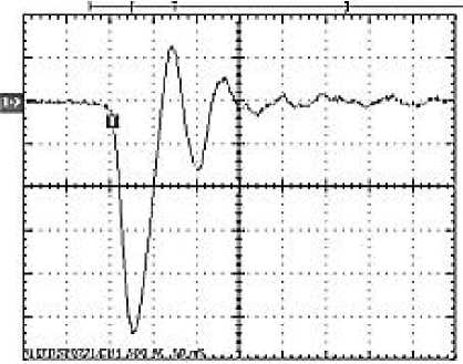
Fig. 1. Interference pulse in the anode circuit of SPT
Parameters of the simulated magnetospheric plasma
|
Impacts |
Impact factors parameters |
|
Electrons |
Е e =70 keV, J e =1∙10–9 А∙ сm–2 |
|
Vacuum |
Oil-free pumping Residual pressure of not more than 10–6 Torr |
|
SPT ceramic temperature |
–45 °C |
Рис. 1. Помеховый импульс в цепи анода СПД
With the aim of developing and testing means of protection against the negative influence of electrostatics on the system SPT–TCS there is a need in experimental work on specialized installations that simulate the effects of magnetospheric plasma, which is very costly both in time and financial [13].
For optimization and minimization of financial and technical supports to conduct testing on the stage of the EGT protection system of SPT–TCS on the technical task of the JSC “ISS” Institute of nondestructive testing of Tomsk Polytechnic University have developed and manufactured test equipment for generating high voltage pulses (HVPG), which allows to simulate a direct injection gained in ceramics in an electric circuit of TCS [14; 15].
The discharge impulse of HVPG has a negative polarity. The impulse front is less than 10 ns. Voltage is adjustable between 3 to 9 kV. Reset charge is from 3∙10–6 to 3∙10–5 C. These characteristics of the discharge pulses correspond to the characteristics obtained by simulation of the impact of MP on the system SPT–TCS using specialized test benches [11; 13].
Technical characteristics of HVPG. The principle of the HVPG is based on generating a high voltage pulse with a negative polarity output voltage and a steep rise front [14]. A pulse is generated at the discharge of the capacitor to the switch. As the switch a hydrogen thyratron with a cold cathode with working gas (“thyratron”) of low pressure is used. The charge of the capacitor and the control of thyratron work are carried by means of electronic circuits, described below.
A structural scheme of HVPG is showed at fig. 2. The input supply voltage through the interference suppress filter (ISF) is supplied to high voltage transformer (HVT) and control system (SC). SC controls the operation of the HVT, the unit of heat generator hydrogen thyratron (UHG), a unit of preionization (UPI) and unit of ignition of the thyratron (UIT). The thyratron is located in the unit of impulse forming (UIF), there is also a replacement high voltage capacitor. The output signal from the UIF is made through a high-voltage cable with contact tip (CT).
Fig. 3. shows the UIF scheme. In the initial state, the capacitance С 0 is charged to voltage U 0 through the diode D 1 . When thyratron T r works a negatively charged С 0 is discharged through R H .
Pulse amplitude of the load voltage depends on С 0 and the value of the complex impedance of the load. Fig. 4, 5 show the form of the high-voltage pulse with U 0 = 3 kV, С 0 = 1000 pF and U 0 = 9 kV, С 0 = 3300 pF, respectively, taken from a low-inductive load RH = 50 Ohm with a high voltage divider with kd = 1:1000.
Changing the values U 0 and С 0 , it is possible to vary widely the amount of electric charge ( Q charge ), passing through the load. Tab. 2 shows the values of Q charge with different values of U 0 and С 0 .
The results of testing. With the help of HVPG experimental researches were conducted that formed the basis for the development and verification of the effectiveness of the protection means of the TCS from the influence of the electrostatic charge effect occurring on ceramic of engine SPT [16].
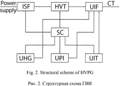
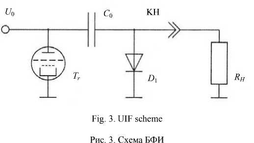
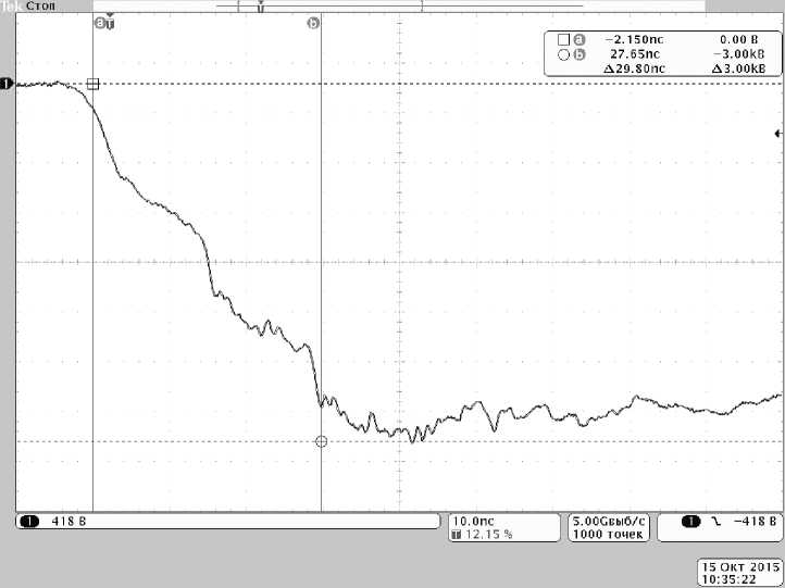
Fig. 4. High voltage pulse form within U 0 = 3 kV, С 0 = 1000 pF
Рис. 4. Форма высоковольтного импульса при U 0 = 3 кВ, С 0 = 1000 пФ
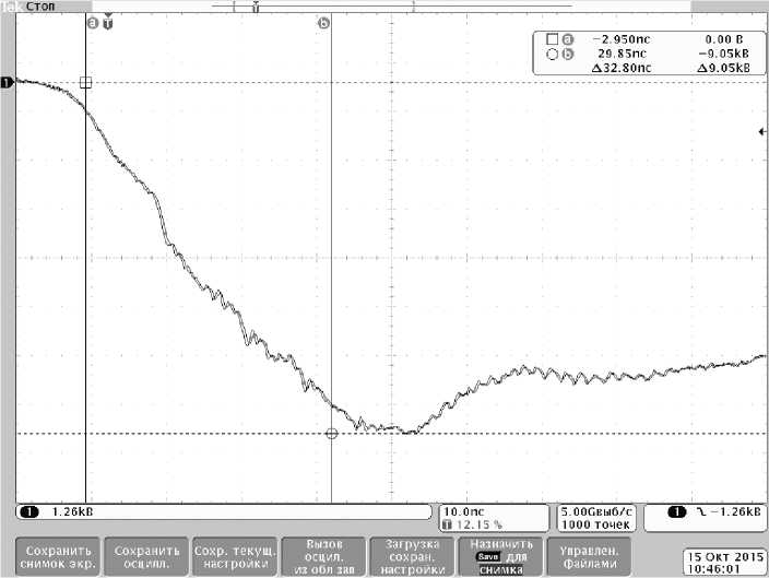
Fig. 5. High voltage pulse form within U 0 = 9 kV, С 0 = 3300 pF
Рис. 5. Форма высоковольтного импульса при U 0 = 9 кВ, С 0 = 3300 пФ
Fig. 6. shows the results of testing. The validation of TCS security means was performed by applying to the input of the protection filter in the circuit of the anode of a series of high-voltage discharge impulses using a generator HVPG with the following characteristics of output voltage on the resistive load of 50 Ohms:
– pulse amplitude – minus 3 kV;
– pulse duration of 10–7 s;
– charge 3 ⋅ 10–6 C;
– number of pulses – 20.
The oscillogram of the output pulse of HVPG on the 50 Ohm load is shown in fig. 7. The amplitude of the negative impulse – minus of 2.94 kV.
During the test, when exposed to a pulse from HVPG at the circuit of the anode to the input cable “Engine-TCS”, the parameters of the discharge pulses at the beginning of “Anode” line and the voltage in the anode circuit of TCS after the protection filter were under control. Measuring at the input circuit was carried out using a voltage divider 1000:1.
Fig. 8 shows the standard oscillogram of voltage in the anode circuit at the input cable “Engine-TCS”.
Fig. 9 shows a typical voltage oscillogram in the anode circuit of high-voltage TCS after protection filter under influence on the circuit of the anode.
Due to the fact that the voltage pulse from the HVPG is fed to the unloaded circuit, the voltage at the beginning of the line and at the end (after the PF) is oscillatory and with the increased amplitude.
The results of measurements of HVPG impact on the circuit of the anode are given in tab. 3.
Conclusion. Developed HVPG allows simulating a direct injection of charge in the investigated electrical circuit. Discharge pulse of HVPG has characteristics that correspond to characteristics obtained by simulation of the impact of MP on the system SPT–TCS using specialized test benches. HVPG is put into operation at the JSC “ISS” and is used when conducting EGT BА. With the help of HVPG experiments on TCS resistance for space craft designed by JSC “ISS”, such as Yamal-400, Express-AM, Telcom etc.
The use of HVPG allows to confirm the effectiveness of the measures taken for the protection of the TCS from the negative impacts of MP on CS at the stage of experimental ground testing (EGT) with minimal time and financial investments.
Table 2
The values of the electric charge at different variable options of HVPG
|
С 0 , pF |
U 0 , kV |
||||
|
3.0 |
4.5 |
6.0 |
7.5 |
9.0 |
|
|
1 000 |
3.00∙10–6 C |
4.50∙10–6 C |
6.00∙10–6 C |
7.50∙10–6 C |
9.00∙10–6 C |
|
1 500 |
4.50∙10–6 C |
6.75∙10–6 C |
9.00∙10–6 C |
1.13∙10–5 C |
1.35∙10–5 C |
|
3 300 |
9.90∙10–6 C |
1.49∙10–5 C |
1.98∙10–5 C |
2.48∙10–5 C |
2.97∙10–5 C |
Рис. 6. Схема испытаний по проверке средств защиты СПУ: ГВИ – генератор высоковольтных импульсов; СПУ-КТ – макет системы питания и управления; ФЗ-КТ – фильтр защиты; УУП-КТ – устройство управления и питания; А – цепь анода; ЭК – экранированная камера; ЗФ – засыпной фильтр; Д – высоковольтный делитель напряжения
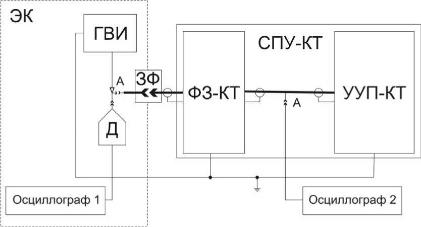
Fig. 6. Testing scheme of the protection means of TCS:
ГВИ (HVPG) – high-voltage pulses generator; СПУ-КТ (TCS-КТ) – the layout of the system of power supply and control; ФЗ-КТ (PF-КТ) – protection filter; УУП-КТ (CPSD) – control and power supply device; A – anode circuit; ЭК (SC) – screened chamber; ЗФ (BF) – bed filter, Д (D) – high-voltage divider
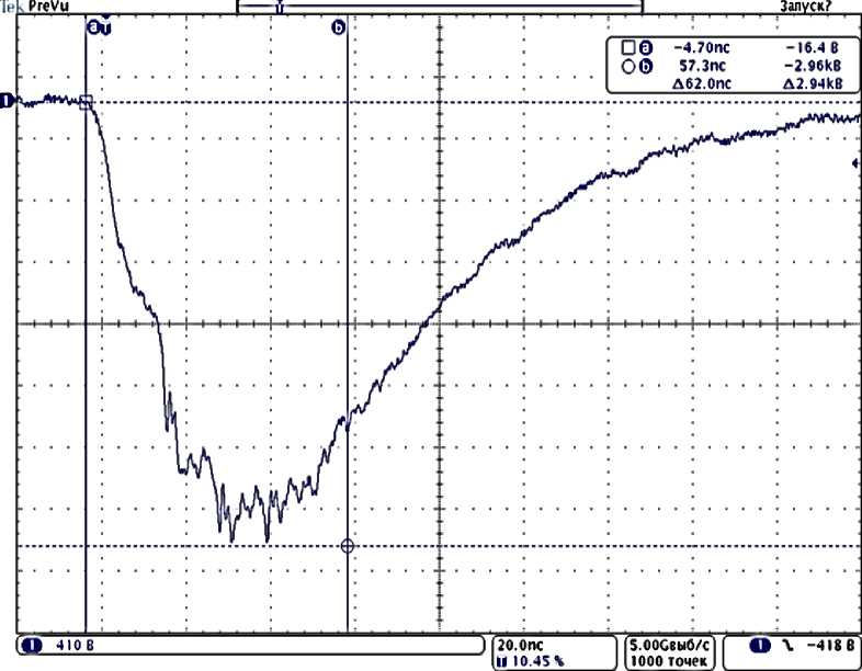
Fig. 7. Output pulse of HVPG on the 50 Ohm load
Рис. 7. Выходной импульс ГВИ на согласованной нагрузке 50 Ом
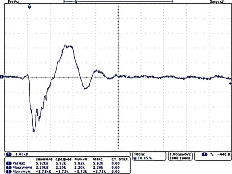
Fig. 8. Voltage at the beginning of the line in the anode circuit
Рис. 8. Напряжение в начале линии в цепи анода
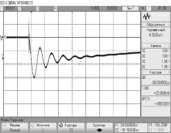
Fig. 9. The voltage in the anode circuit of the TCS layout after protection filter under the influence on the circuit of the anode
Рис. 9. Напряжение в цепи анода макета СПУ после фильтра защиты при воздействии в цепь анода
The results of measurements
Table 3
|
The voltage swing at the beginning of the line to the inlet of the cable “Engine-TCS”, V |
5920 |
|
The voltage swing at the outlet PF, V |
236 |
References Simulation means of electrostatic discharges in the system “stationary plasma thruster - transformation and control system”
- Модель космоса. В 2 т. Т. 2. Воздействие космической среды на материалы и оборудование космических аппаратов/под ред. М. И. Панасюка, Л. С. Новикова. М.: КДУ, 2007. 1144 с.
- Horwitz J. L. Dynamics of Magnetospheric Plasmas//Journal of spacecraft and rockets. 1985. Vol. 22, № 3. P. 225-230.
- Максимов И. А., Кочура С. Г. Исследование влияния факторов космического пространства и техногенных факторов на космические аппараты, разработка методов и средств защиты: монография/Сиб. гос. аэрокосмич. ун-т. Красноярск, 2011. 182 с.
- NASA-HDBK-4002A, Mitigating in-space charging effects -a guideline. NASA, 2011, 181 p.
- Основные правила повышения безопасности космических аппаратов в условиях радиационной электризации/Г. В. Бабкин //Руководство для конструкторов/ЦНИИМаш. ГОНТИ-1, 1990. 179 с.
- Моделирование радиационной электризации конструкционных материалов космических аппаратов/Д. А. Трофимчук //Тр. Всерос. конф. студенческих науч.-исслед. инкубаторов (15-17 мая 2014, г. Томск)/под ред. В. В. Демина. Томск: Изд-во НТЛ, 2014. 180 с.
- Проблема электростатических разрядов в элек-трореактивной двигательной подсистеме геостационарного космического аппарата/Д. А. Трофимчук //Актуальные вопросы проектирования автоматических космических аппаратов для фун тальных и прикладных научных исследований/дамен-сост. ни С. В. В. Ефанов. Химки: Изд-во ФГУП «НПО име А. Лавочкина», 2015. С. 285-289.
- Проблема электростатических разрядов в элек-трореактивной двигательной подсистеме геостационарного космического аппарата/Д. А. Трофимчук //Вестник СибГАУ. 2015. Т. 16, № 2. С. 404-410.
- Garret H. B. The geosynchronous plasma environment, AIAA Paper 90-0289. 1999. 16 p.
- Отчет по результатам теоретических и экспериментальных исследований электризуемости керамик различных марок под действием электронов с энергиями 70-100 кэВ и плотностью тока 0,5-1 нА/см2, в диапазоне температур плюс 20 °С до минус 50 °С: техн. отчет/Зыков М. В., Бежаев Ю. А. и др. О1-5-156/13. Томск: ИНК ТПУ, 2014. 14 с.
- Отчет по результатам проведения тестовых экспериментов по исследованию помеховых сигналов, наводимых в электрических цепях СПУ при воздействии электронов магнитосферной плазмы с энергиями 70-100 кэВ и плотностью тока 0,5-1 нА/см2: техн. отчет/Зыков М. В., Бежаев Ю. А. и др.//О2-5-156/13. Томск: ИНК ТПУ, 2014. 17 с.
- Наземные стендовые испытания космических аппаратов на стойкость к воздействию радиационной электризации/О. С. Графодатский //Руководство для конструкторов/ЦНИИМаш. ГОНТИ-1, 1992. 157 с.
- Проблемы расчетно-экспериментального моделирования радиационной электризации разрядной камеры высокоимпульсного холловского двигателя системы коррекции космического аппарата/Ю. А. Бежаев //Радиационная стойкость электронных систем -Стойкость-2014: науч.-техн. сб. тезисов докладов. М.: Изд-во ФГУП «НИИП», 2014. С. 263-265.
- Изготовление макета генератора для имитации прямой инжекции сброшенного разрядного заряда в схему питания стационарного плазменного двигателя: техн. отчет/Зыков М. В., Бежаев Ю. А. и др.//Томск: ИНК ТПУ, 2013. 13 с.
- Экспериментальная оценка стойкости блока управления холловским двигателем СПД-100 подсистемы коррекции к воздействию радиационной электризации космического пространства/Ю. А. Бежаев //Радиационная стойкость электронных систем -Стойкость-2014: науч.-техн. сб. тезисов докладов. М.: Изд-во ФГУП «НИИП», 2014. С. 261-263.
- Разработка и экспериментальная отработка методов и средств защиты системы управления высоко-импульсного блока коррекции на базе холловского двигателя для геостационарных космических аппаратов от электростатических разрядов: техн. отчет/Зыков М. В., Чигорко А. А. и др.//ТО1-156/13-3-15. Томск: ИНК ТПУ, 2014. 45 с.
