Software system for mathematical simulation of the electronic beam welding process

Author: Murygin A. V., Tynchenko V. S., Kurashkin S. O., Bocharov A. N., Petrenko V. E.
Journal: Siberian Aerospace Journal @vestnik-sibsau-en
Section: Informatics, computer technology and management
Article in issue: 2 vol.22, 2021.
Free access
Within the framework of this study, a software system for modeling the distribution of the temperature field in the steady-state mode of the electron-beam welding process for thin-walled aerospace structures is proposed. The purpose of creating such a software system is to improve the quality of control of the electron-beam welding process and, accordingly, to reduce the number of defects in welded joints of thin-walled structures. The software system has a model structure and implements the energy distribution models proposed earlier by the authors. The MySQL database management system and the Embarcadero RAD Studio programming system were chosen as the means of implementing the program. The central link of the system is a database that allows you to store and process information both on mathematical modeling and on the results of simulation and field experiments. The article describes the structure of the developed software system, and also presents algorithms for the operation of its constituent modules. The system provides the user with the opportunity not only to carry out simulation according to the specified technological parameters (welding speed, accelerating voltage, beam current, boundary conditions, simulation time, product material), but also to visualize the results and save them in a single database. The use of the proposed system allows not only to minimize the costs of the enterprise for the development of technological parameters of the steady state for the electron-beam welding process, but also to create a flexible information base for collecting experimental information with the aim of further automating and intellectualizing the technological process of creating permanent joints in the framework of Industry 4.0.
Electron-beam welding, modelling, technological parameters, software, optimisation, normal distribution law.
Short address: https://sciup.org/148321803
IDR: 148321803 | UDC: 621.791.722 | DOI: 10.31772/2712-8970-2021-22-2-261-274
Text of the scientific article Software system for mathematical simulation of the electronic beam welding process
The basis of electron beam welding is the use of thermal energy released during the deceleration of a sharply focused stream of electrons accelerated to high energy levels.
The process of electron beam welding as a whole is considered in sources [1–3], where the authors propose to conduct research on various metals and in various branches of mechanical engineering. The wide possibilities of electron beam welding make it possible to use this technology for the manufacture of various types of products. For example, the authors of [4–6] use the technology of electron beam welding to obtain a channel for heating the blades of the inlet guide vane of gas turbines, and also determine the optimal options for the constructible structure of the welded joint, depending on the amount of allowance for machining.
Studies carried out in [7–9] have shown that during electron beam welding of tungsten single crystals, conditions are provided for epitaxial crystallization of the weld material, as a result of which its parameters correspond to the parameters of the single crystals being welded. After welding the joints using electric spark cutting, the technological sections are separated from the workpiece. Thus, a hollow monohedral tube is obtained, which is further used to produce the cathode of a thermionic converter.
At present, in order to further improve the quality of the technological process of electron-beam welding, many authors have carried out mathematical modeling of this technological process in differ- ent modes and with different materials. For example, the authors of [10–12] considered the multicriteria optimization of the electron beam welding process using experimental data obtained on the basis of real exact models of the electron beam welding process, which describe the dependence of the geometry of welded joints on stainless steel on the parameters of the electron beam welding mode. In turn, the authors of [13–15] investigated the processes of formation of a melting channel in electron beam welding with full penetration of the material.
Within the framework of this study, a dynamic mathematical model has been proposed that makes it possible to describe the formation of a reverse bead of a welded seam depending on the parameters of the technological process of electron beam welding. The mathematical model of the processes of evaporation, condensation, and diffusion of the AMg-6 alloy in electron beam welding with dynamic positioning of the electron beam is described in [16–18]. The developed model makes it possible to predict the chemical composition of welds in electron beam welding.
The model was verified by comparing it with the results of the analysis of the chemical composition of the penetration zones in the material. The development of electron beam welding technology, the development of new control methods for this technological process gave rise to a wide range of modes of action of an electron beam on the surface of the parts to be welded. In [19–21], a differential heat conduction equation is presented, which is a mathematical model of a whole class of heat conduction phenomena.
The authors of [22–24] developed a mathematical model of scanning electron beam welding, which made it possible to simulate the dynamics of the technological process and obtain a criterion for its optimization.
Mathematiacal support of the software
The software system proposed in the study allows calculating the distribution of the temperature field for given process parameters, such as:
-
1. Welding speed.
-
2. Accelerating voltage and beam current.
-
3. The considered coordinate area (coordinate limits and grid step).
-
4. Time of exposure.
-
5. Product material.
All the above-described parameters stored in the database are used as input data for the model, and the output is vector temperature correspondences depending on coordinates and time. In addition, the data obtained during the simulation, if necessary, can be used to optimize the parameters of the electron beam welding (EBW) process within the framework of the investigated mode. For this, the possibility of both data export and integration into the software system of the module for optimization is provided.
In accordance with fig. 1 point source of heat of constant power q moves with constant speed v rec-tilinearly from point O 0 in the direction of the x -axis. Since the moment of movement of the source, time t н has passed and it is at point O . Together with the source of heat, a moving coordinate system move, the origin of which coincides with the location of the heat source, i.e with point O [25].
As the basic formulas for calculating the temperature field [25], expressions are used that describe the actions of an instantaneous point source on the surface of a semi-infinite body (1) and a linear source in an infinite plate (2):
^ VT tv T x + y + Z1
T( x, y, z, q, v, t ) = Th +---- q 3 e 2 a Je 4 a 4 aT ^/2,(1)
cp J( 4na) о where x, y, z are the coordinates of the point in question in space; q is the effective power of the electron beam; v is the welding speed; t is the time counted from the moment the source passes through the section in which the point under consideration is located; Tн is the initial temperature of the product; сρ is the heat capacity of the material; a is a coefficient of thermal diffusivity; τ = t – t’ is the duration of heat propagation in the moving coordinate system; t is the current moment in time; t’ is a certain moment of time after the start of heating, in which the heat source is located at point O’ with coordinates (vt’, 0 , 0) (fig. 1).
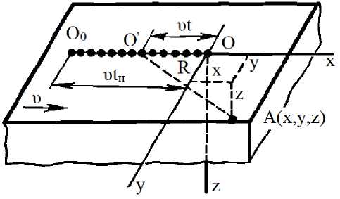
Рис. 1. Схема движения непрерывно действующего точечного источника на поверхности полубесконечного тела мощностью q , перемещающегося со скоростью v
-
Fig. 1. Scheme of motion of a continuously acting point source on the surface of a semi-infinite body of power q , moving with speed v
In accordance with fig. 2, a linear heat source of power q with a uniform distribution over the thickness of the plate moves at a constant speed v. Boundary planes z = 0 and z = δ give off heat to the environment, the temperature of which Tн is equal to the initial temperature of the body [25].
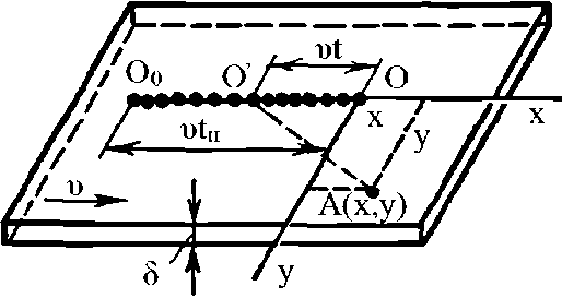
Рис. 2. Схема движения непрерывно действующего линейного источника в бесконечной пластине мощностью q , перемещающегося со скоростью v
-
Fig. 2. The scheme of motion of a continuously operating linear source in an infinite plate of power q , moving with a speed v
vx t v T _ 2^т x + У
. 2 a e 4 a c p5 4 a т
T 2 ( x , y , q , v , t ) = T H + q—e
4 лло
Where δ is the thickness of the product; λ is the coefficient of thermal conductivity; t is the warmth propagation time.
In this paper we apply the model of power, representing a function (3), recorded as follows: Q = I ⋅ U ⋅η⋅ 0,24, (3)
Where U is accelerating voltage; I is a beam current; η is efficiency.
A complex fast-moving source was selected as a combination of two sources - a point and a linear one, equivalent to the real ones, taking place in the literature [25]. The calculation of the value of the functional is performed for an area whose dimensions are comparable to the dimensions of the penetration channel.
These formulae allow, when they are added (superposition of sources) in the process of calculation, to describe the nature of the distribution of thermal energy after exposure to an electron beam.
The algorithm for calculating the model is shown in fig. 3.
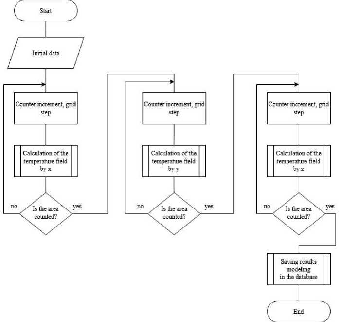
Рис. 3. Алгоритм математического моделирования теплового поля
Fig. 3. Algorithm for mathematical modeling of the thermal field
At the initial stage of the algorithm shown in Fig. 3, the original data is received from the corresponding record in the database. Further, a sequential calculation of the temperature field is carried out along three coordinate axes; the results obtained are recorded in the database and remain available for further analysis and use.
Fig. 4 shows a block diagram of the sub-process for calculating the field in one coordinate. Its cyclic use in all directions makes it possible to obtain a temperature field.
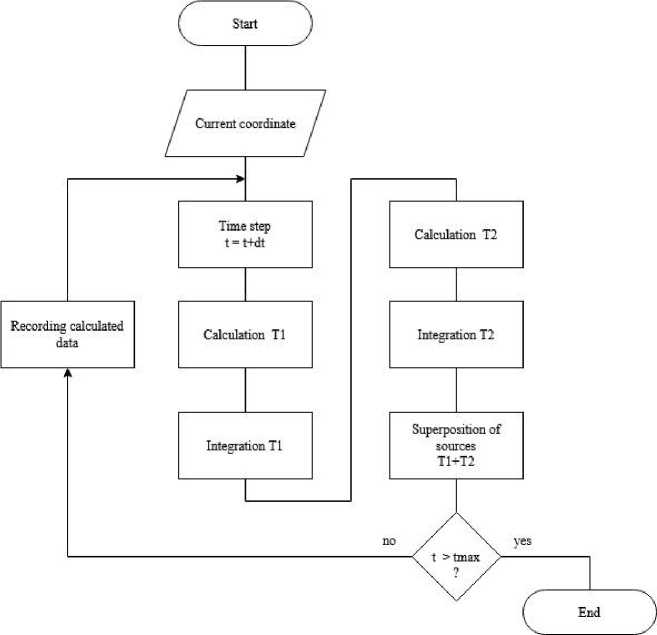
Рис. 4. Алгоритм подпроцесса расчета температурного поля в рамках одной координаты
Fig. 4. Algorithm for the sub-process of calculating the temperature field within one coordinate
Within the software system, a graphical display of simulation results is available, which can be carried out according to the principle of assigning axes and the corresponding codependent value.
This module of the software environment allows the operator to assess the feasibility of certain technological modes, which in turn, greatly facilitates the task of exploratory research in field experiments.
Software design
The software system for mathematical modeling of the electron beam welding process was developed in the C ++ language and is a Windows application that can work in the environment of Windows 7/8/10 operating systems. The block diagram of the software system is shown in fig.5.
The software system consists of 6 modules with the following functions:
-
1. The module of mathematical modeling implements the model of the electron beam welding process.
-
2. The module for editing the parameters of the model carries out the input and editing of the physical parameters of materials, the parameters of the ELS process and the parameters of the product.
-
3. The simulation data import module carries out the input of data and simulation graphs implemented in third-party simulation software products, Comsol Multiphysics and Ansys.
-
4. The module for importing data from a full-scale experiment carries out the input of the results of full-scale experiments carried out on an electron-beam installation, including photographs of thin sections, a description of welding defects, etc.
-
5. The graphics module provides graphical construction of the results of mathematical modeling of the ELS process.
-
6. The data viewing module displays and edits the results of simulation and field experiments.
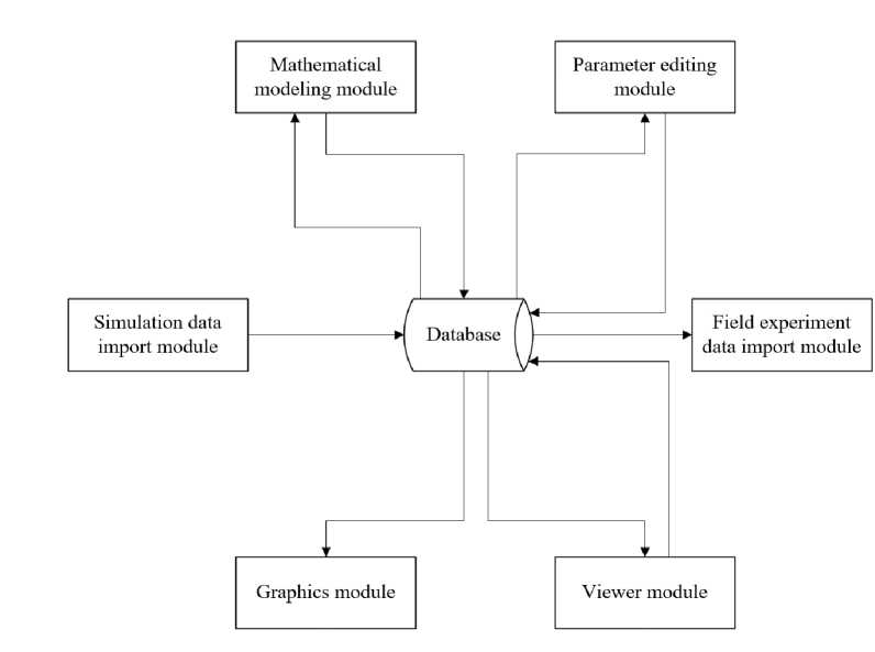
Рис. 5. Структурная схема программной системы математического моделирования процесса ЭЛС
Fig. 5. Block diagram of the software system for mathematical modeling of the EBW process
The block diagram of the software system is shown in Fig.6.
The central object of the system is an experiment, which can be presented as the result of a mathematical model, simulation and field experiments. Work in the software system begins with the creation of an experiment and the determination of its parameters (material properties, parameters of the ELS process, product parameters). You can also work with experiments that are already in the system by editing their parameters.
After saving the parameters of the experiment, it is necessary to select one of the actions: start mathematical modeling of the ELS process, load the data of simulation and full-scale experiment, edit and view the data already obtained. As a result of performing actions, there is a constant interaction with the database.
At the end of all manipulations with experiments and their results, you must log out of the system.
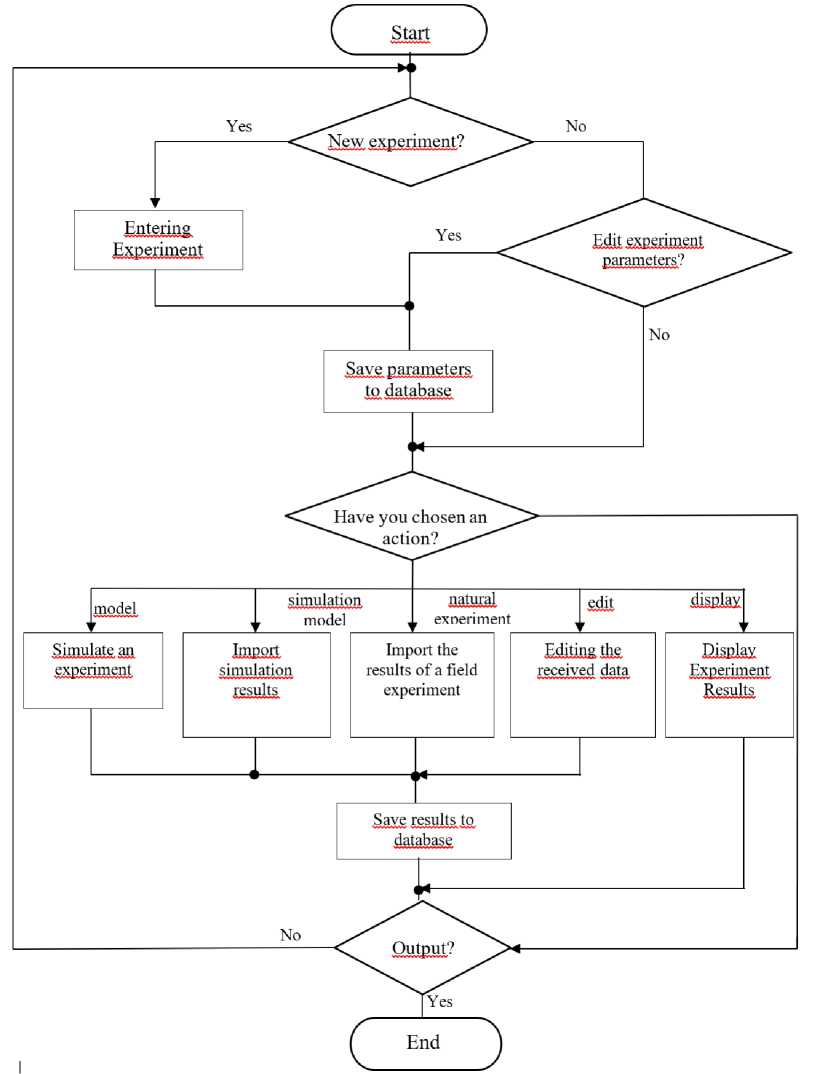
Рис. 6. Блок-схема работы программной системы моделирования ЭЛС
Fig. 6. Block diagram of the EBW simulation software system
Information support of the software system
The central link table is the experiment table. Physical parameters of materials, EBW process parameters, and product parameters are stored in the material table, techprocess and workpiece tables, respectively. These parameters describe the experiment and are used for mathematical modeling of the process. The modeling and data_modeling tables are designed to store the results of mathematical modeling of the ELS process, and the simulation and data_simul tables are designed to store the results of the simulation modeling carried out in third-party software products. The practice table stores the results of field experiments.
□ data model
□ modeling
< id_dm f id_model dm_time
DECIMAL DECIMAL DECIMAL DECIMAL
dm_temperature DECIMAL
* Ограничения + Индексы
DECIMAL DECIMAL
VARCHAR
modeLcomment TEXT
+ Ограничения + Индексы
□ practice
joint_width joint_depth
INT
INT DATETIME
FLOAT
VARCHAR
VARCHAR
3 id_exp____ f id_material INT
f id_tp f id_wp
pr description TEXT
Ограничения
Индексы
J data_simul
^ id_ds f id—Simui ds_ttme
INT
INT
DECIMAL DECIMAL DECIMAL DECIMAL
ds.temperature DECIMAL
Ограничения
Индексы
^ material
? immaterial
INT
VARCHAR name heat_conductivity FLOAT
1 workpiece
FLOAT
FLOAT
FLOAT heat_capacity density V-capacity k_conductlvity Ограничения
23 experiment
wp_comment VARCHAR
* Ограничения
INT INT
modeLexp INT simuLexp INT pract_exp INT description VARCHAR
Ограничения
* Индексы
~1 simulation
? id simul INT
s_time data s.chart
□ techprocess
? Id tp
DECIMAL DECIMAL DATE VARCHAR
s. comment TEXT Ограничения Индексы
v_weiding u_uskor power d_beam tp_name
INT
FLOAT FLOAT FLOAT FLOAT
VARCHAR
tp_comment VARCHAR
+ Ограничения
Рис. 7. Структурная схема базы данных программной системы моделирования ЭЛС
Fig. 7. Block diagram of the database of the EBW modeling software system
Description of the software system operation
Fig. 8 shows the basic form of the software system for mathematical modeling of the ELS process.
The main form has four tabs: experiment planning, modeling, simulation, natural experiment. The work of the software system begins with the main tab - experiment planning. This tab is designed to control the modeling process. Here new experiments are created or old ones are displayed, experiment parameters are displayed, and new simulation conditions are set.
This tab is divided into three main blocks: material, process technology and product. In these blocks, the physical parameters of the product material, the parameters of the ELS process and the parameters of the product itself are specified. The specified parameters will then be used to simulate the ELS process.
Each block contains a block of buttons for defining new materials, processes and products. Gray color of the labels indicates that the blocks are in the information display mode. Black color signals the input of experimental conditions. At the bottom of the screen, there is a list of experiments, the parameters of which are displayed above. The block of buttons allows you to create, delete, save and edit experiment conditions. The block "State of the experiment" displays the fullness of the experiment, that is, whether the simulation was carried out, whether the data of the simulation and the fullscale experiment were loaded.
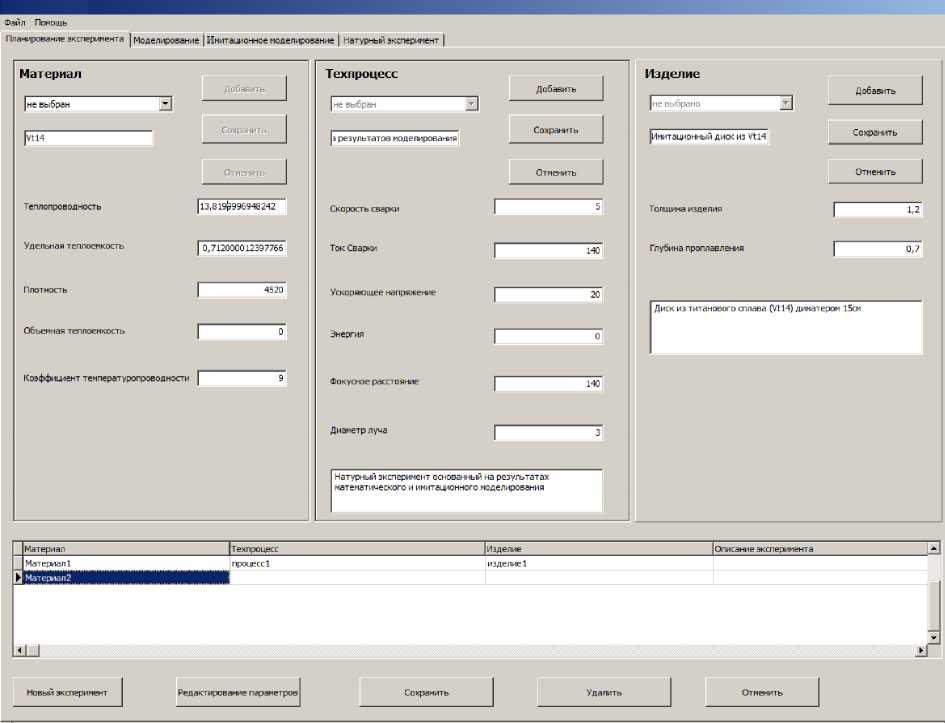
Рис. 8. Основная форма программной системы математического моделирования ЭЛС
Fig. 8. The main form of the software system for mathematical modeling of EBW
Conclusion
Within the framework of this study, a software system for modeling the distribution of the temperature field in the steady-state mode of the electron-beam welding process for thin-walled aerospace structures is proposed. The software system has a model structure and implements the energy distribution models proposed earlier by the authors. The central link of the system is a database that allows you to store and process information both on mathematical modeling and on the results of simulation and field experiments. The use of the proposed system allows not only to minimize the costs of the enterprise for the development of technological parameters of the steady state for the electron-beam welding process, but also to create a flexible information base for collecting experimental information for the purpose of further automation and intellectualization of the technological process of creating permanent joints within the framework of Industry 4.0.
References Software system for mathematical simulation of the electronic beam welding process
- Yunlian Q., Ju D., Quan H., Liying Z. Electron beam welding, laser beam welding and gas tungsten arc welding of titanium sheet. Materials Science and Engineering A. 2000. Vol. 280, No. 1. P. 177–181.
- Salomatova E. S. [Electron beam welding - from invention to the present day]. Bulletin of the Perm National Research Polytechnic University. Mechanical engineering, materials science. 2013. No. 1. P. 74–87. (In Russ.)
- Permyakov G. L., Olshanskaya T. V., Belenkiy V. Ya., Trushnikov D. N. [Simulation of electron beam welding to determine the parameters of welded joints of dissimilar materials]. Bulletin of the Perm National Research Polytechnic University. Mechanical engineering, materials science. 2013, No. 4, P. 48–58. (In Russ.)
- Sharonov N. I. [Application of electron-beam welding in turbine construction]. Nauchno-tekhnicheskie vedomosti SPbPU. Natural and engineering sciences. 2010, No. 3 (106), P. 170–175. (In Russ.)
- Denlinger E. R. Thermo-mechanical modeling of large electron beam builds. Thermo-Mechanical Modeling of Additive Manufacturing. – Butterworth-Heinemann. 2018, Vol. 150, No. 2, P. 167–181.
- Raj R. A., Anand M. D. Modeling and prediction of mechanical strength in electron beam welded dissimilar metal joints of stainless steel 304 and copper using grey relation analysis. Int. J. Eng. Technol. 2018, Vol. 7, No. 1, P. 198–201.
- Lastovirya V. N., Novokreshchenov V. V., Rodyakina R. V. [The use of electron beam welding to create thermoemission converters (TEC) from tungsten single crystals]. Global Nuclear Safety. 2015, No. 3 (16), P. 27–35. (In Russ.)
- Chowdhury S., Yadaiah N., Khan S. M., Ozah R., Das B., Muralidhar M. A perspective review on experimental investigation and numerical modeling of electron beam welding process. Materials Today: Proceedings. 2018, Vol. 5, No. 2, P. 4811–4817.
- Wang J., Hu R., Chen X., Pang S. Modeling fluid dynamics of vapor plume in transient keyhole during vacuum electron beam welding. Vacuum. 2018, Vol. 157, No. 1, P. 277–290.
- Mladenov G., Koleva E., Belenky V. Ya., Trushnikov D. N. [Modeling and optimization of electron beam welding of steels]. Bulletin of the Perm National Research Polytechnic University. Mechanical engineering, materials science. 2014, Vol. 16, No. 4, P. 7–21. (In Russ.)
- Kanigalpula P. K. C., Jaypuria S., Pratihar D. K., Jha M. N. Experimental investigations, input-output modeling, and optimization of spiking phenomenon in electron beam welding of ETP copper plates. Measurement. 2018, Vol. 129, No. 1, P. 302–318.
- Luo M., Hu R., Liu T., Wu B., Pang S. Optimization possibility of beam scanning for electron beam welding: Physics understanding and parameters selection criteria. International Journal of Heat and Mass Transfer. 2018, Vol. 127, No. 1, P. 1313–1326.
- Belenky V. Ya., Trushnikov D. N., Piskunov A. L., Lyalin A. N. [Dynamic model of electron beam welding with through penetration]. Bulletin of the Perm National Research Polytechnic University. Mechanical engineering, materials science. 2011, Vol. 13, No. 3 (5), P. 72–84. (In Russ.)
- Das D., Pratihar D. K., Roy G. G. Cooling rate predictions and its correlation with grain characteristics during electron beam welding of stainless steel. The International Journal of Advanced Manufacturing Technology. 2018, Vol. 97, No. 5-8, P. 2241–2254.
- Tadano S., Hino T., Nakatani Y. A modeling study of stress and strain formation induced during melting process in powder-bed electron beam melting for Ni superalloy. Journal of Materials Processing Technology. 2018, Vol. 257, No. 1, P. 163–169.
- Salomatova E. S., Trushnikov D. N., Tsaplin A. I. [Simulation of evaporation processes in electron beam welding with dynamic positioning of the electron beam]. Izvestiya Tula State University. Technical science. 2015, No. 6-2, P. 124–133. (In Russ.)
- Węglowski M. S., Błacha S., Phillips A. Electron beam welding–Techniques and trends–Review. Vacuum. 2016, Vol. 130, No. 1, P. 72–92.
- Trushnikov D. N., Belenki'y V. Y., Mladenov G. M., Portnov N. S. Secondary Emission signal for weld formation monitoring and control in eletron beam welding (EBW). Materialwissenschaft und Werkstofftechnik. 2012, Vol. 43, No. 10, P. 892–897.
- Olshanskaya T. V., Fedoseeva E. M., Koleva E. G. [Construction of thermal models in electron beam welding by the method of Green’s functions]. Bulletin of the Perm National Research Polytechnic University. Mechanical engineering, materials science. 2017, Vol. 19, No. 3, P. 49–74. (In Russ.)
- Trushnikov D. N., Belenkiy V. Ya. [Investigation of the formation of a secondary current signal in plasma during electron beam welding with electron beam oscillation]. Welding production. 2012, No. 11, P. 9–13. (In Russ.)
- Nishimura F., Nakamura H., Takahashi H., Takamoto T. Development of a new investment for high-frequency induction soldering. Dental materials journal. 1992, Vol. 11, No. 1, P. 59–69.
- Wang D., Wang S., Zhang W. Numerical Simulation and Experimental Investigation on Ti70 Titanium Alloy Electron-Beam-Welded Joint. Transactions of the Indian Institute of Metals. 2020, Vol. 73, No. 9, P. 2361–2369.
- Lanin V. L., Sergachev I. I. Induction devices for assembly soldering in electronics. Surface engineering and applied electrochemistry. 2012, Vol. 48, No. 4, P. 384–388.
- Moghaddam M., Mojallali H. Neural network based modeling and predictive position control of traveling wave ultrasonic motor using chaotic genetic algorithm. International Review on Modelling and Simulations. 2013, Vol. 6, No. 2, P. 370–379.
- Konovalov A. V. Teoriya svarochnykh protsessov [Theory of welding processes]. Moscow, Izd-vo MGTU im. N. E. Bauman Publ., 2007, 752 p.
- MySQL. Available at: https://www.mysql.com/ (accessed 01.05.2021)
- Challawala Sh., Lakhataria J., Mehta Ch., Patel K. MySQL dlya bol'shikh dannykh [MySQL for Big Data]. Moscow, DMK Press Publ., 2018, 226 p.
