Solution of the filtration problem with the optimal adjustment of the radio-reflecting net of a transformable reflector

Author: Kabanov S.A., Mitin F.V.
Journal: Siberian Aerospace Journal @vestnik-sibsau-en
Section: Informatics, computer technology and management
Article in issue: 4 vol.22, 2021.
Free access
In this paper, we consider the solution of the filtering problem using the Kalman filter with the optimal tuning of the radio-reflecting net. A large-sized transformable space-based reflector is considered. In the process of this structure placing in orbit, it is possible that the real form of the radio-reflecting net can deviate from the desired one. To ensure point-to-point adjustment of the active part of the mesh, a cable-cable system is used. The nodal points of the radio-reflecting surface are connected to the back side of the net through cables. They have built-in actuators that allow one to change the length of the cables. A piezo actuator was selected as a control device. By point-by-point adjustment of the piezo actuators the net is stretched to the required shape. This ensures a high-quality radiation pattern and a high signal level when receiving and transmitting data. Specific values of the disturbing influences are given. To measure the supply voltage on the piezo actuator and the cable length, a voltage converter and a laser scanner are used. Possible deviations from the calculated initial position are determined. In accordance with the principle of separation, the estimation problem is solved first, then the control problem. The estimation problem is solved using the Kalman filter. The control problem is solved using the optimal control algorithm according to the hierarchy of target criteria. The results of numerical simulation are presented. The successful solution of the problem is shown with variable values of measurement noise and disturbing influences. Comparison with trajectories obtained applying various optimal control algorithms is given.
Sequential optimization algorithm, large-sized transformable reflector, radio-reflecting net, piezo actuator, mathematical model, modeling
Short address: https://sciup.org/148329590
IDR: 148329590 | UDC: 517.977.5-629.783 | DOI: 10.31772/2712-8970-2021-22-4-577-588
Text of the scientific article Solution of the filtration problem with the optimal adjustment of the radio-reflecting net of a transformable reflector
Currently, communication satellites are actively employed to solve a wide range of problems [1; 2]. One of the efficient ways to implement such satellites is the creation of large space reflectors [3–5]. Active developments are underway in this area. These systems make it possible to operate simultaneously at several frequencies and have a large exposure area [6–9].
Let us consider the implementation of a large-sized space structure using a cable-stayed system to create the necessary shape of the radio-reflecting surface of the reflector (fig. 1) [10–14]. A large-sized transformable reflector (LTR) consists of a spacecraft (SC) 1. Deployable elements are attached to it, such as solar panels 2 , an irradiating system 3 . To provide a given radiation pattern, the rod 4 extends the reflector 5 to the required focal length. The reflective surface is net 6 .
For the effective use of communication satellites, it is necessary to maintain the exact shape of the radio-reflecting net 6 . This ensures a high-quality radiation pattern and a high signal level when receiving and transmitting data [15; 16].
Due to the equipment operation in outer space, periodic disturbing effects on the reflector parts occur. Such disturbances are caused by changes in the temperature regime, presence of radiation, and the solar wind [17; 18]. In the process of obtaining data about the state of the radio-reflecting surface shape, it is necessary to take into account the influence of measurement noise. In view of the limited energy resources on the reflector, it is important to minimize energy costs.
Fig. 1. The design of the LTR (Large-sized transformable reflector)
Рис. 1. Конструкция крупногабаритного трансформируемого рефлектора
Thus, it is necessary to carry out a point adjustment of the net while minimizing energy costs, taking into account the influence of measurement noise and external disturbances.
Mathematical description of the problem
Fig. 2 shows one LTR spoke in cross section, where 1 is the spoke , 2 and 3 are the outer and rear nets, and 4 are the cables into which the actuators are installed. It is necessary, by changing the length of the cables 4 with the help of the actuators 5 , to set the desired shape of the radio-reflecting net 2 , thereby providing the required radiation pattern. A piezodrive was considered as an actuator. The desired shape is set in ground conditions. In the process of delivering the LTR to a given orbit and during the system opening, a slight shift in the real shape from the desired one may occur. After deployment, the checkpoints are revised and the actuators 5 are controlled to change the length of the cable 4 .
Fig. 2. The spoke in cross section
Рис. 2. Спица в сечении
A piezo actuator of the APM type [19] with a displacement of l max = 10 mm with a displacement tolerance of ±15% was chosen as an actuator to control the setting of the radio-reflective net. To measure the voltage at the input of the piezo actuator, a measuring voltage converter PIN-50-U-4/20-DH [19] was employed with a basic reduced error of no more than 1.5%. To measure the change in the cable length, a RangeVision Standard Plus laser scanner [21] is used with an accuracy of ±0.03 mm.
The system of differential equations, describing a piezoelectric element with an executive body based on the findings of A. A. Nikolsky [22], has the form X = f(X, u, t) + ξx, where X = (l V Uэ)T is the state vector, ξx = [ξx1 ξx2 ξx3]T is noise with intensity Bx = diag(Bx1, Bx2, Bx3). Or in element-wise form l = V + ^ x1, у = NKoUe + Fs - Kell - KdV + m x'
KV
Ue =---eeUep— eC0RintKd C0RintKd C0Kd where l is the change in the length (stroke) of the actuator; V is the actuator extension speed; N is the number of elements; K0 is the coefficient of the inverse piezoelectric effect; Ue is the electrical voltage applied to the actuator electrodes; Fs – static force; Kel – elasticity coefficient; Kd – coefficient of internal damping; ee is the voltage from the source of the electromotive force; C0 – capacity; Rint – internal resistance; Kp is the coefficient of the direct piezoelectric effect; mΣ is the total mass, consisting of the piezo actuator’s mass and the mass being moved.
A generally accepted in practice problem statement of the cooperative synthesis of linear systems optimal control is based on the separation theorem. According to this theorem, the optimal control system consists of an optimal filter, which forms estimates of the system state vector, and an optimal controller, which determines the control already in a deterministic setting under the assumption that the state vector is precisely known [23–25]. In this article the Kalman filter and the sequential optimization algorithm [26] are applied to build the control.
The extension length and the voltage on the piezo actuator are available for measurement. Let us consider the observation equation in the form z = Hx + $ z, (2)
where z = [ z 1 z 2 ]T, H = [1 0 1]T, ξ z = [ ξ z 1 ξ z 2 ]T – random processes similar to blank noise with the strength of B z = diag ( B z 1 , B z 2 ).
The optimal estimate can be obtained using the Kalman filter
— = V + Rn Bz1 (zi -l) + R13B-2 (z2 - Ue ), dVˆ dt
NK o U e + F s - K el l - K d V - 1
-------------------------+ R 21 B z 1 m ^
( z1 l ) + R 23 B z 2 ( z 2
—
U e ) ,
dU ˆ e dt
e e U ˆ e K p V
—
C 0 R int K d C 0 R int K d C 0 Kd
+ R 31 B - 2 ( Z i - 1 ) + R 33 B z 2 ( Z 2 - U e ) .
R = AR + RA T - RH T B - ’HR + B x , R ( 1 0 ) = R o,
|
where 0 1 0 A= _ K el _K d NK 0 /m m. m 0 K p 1 |
, R nn ( t 0 ) 9 ® хп , |
|
L ~ C 0 K d C 0 R int K d J The remaining elements of the matrix of initial estimation e |
ror covariance were taken equal to zero. |
Control problem statement
To solve the control problem, an optimal control algorithm is used according to the hierarchy of target criteria [26]. In addition to fulfilling the terminal conditions, it is necessary to reduce energy costs. In case of controlling a piezo actuator, this is the power released on the piezo actuator during the control process.
The control is calculated as u = u 1 + u 2, where u 1 and u 2 minimize performance criteria of J 1 and J 2 , respectively
J1 = Vf 1(X, tf), tf
J = V2(X,tf ) + J[f(X,t) + 0,5(u2 + u02)2k22]dt, t0
where V f 1 = 0,5β 1 [ V ( t f ) – V f ]2, V f 2 = 0,5Δ X f T ρ k Δ X f ; f 0 = 0,5β 2 [ l ( t ) – l f ]2 + 0,5β 3 P e ( t ); ρ k = diag (ρ 1 , ρ 2 , ρ 3 , ρ 4 ), β 1 , β 2 , β 3 , k 2 are given coefficients; Δ X f = X ( t f ) – X f , X f = ( l f V f U e f )T is the given end value of the vector X in (1), p = UtI = ( ee - Ue ) 2 / R^ is electric power; U t is total applied voltage; I is current. The solution of the control problem in a deterministic formulation is in-depth considered in the work [22] .
To assess the effect of disturbances on the system, it is necessary to determine the magnitudes of external disturbances and measurement noise. In addition to external disturbances, a change in the initial and final states can be observed, caused by the impact on the structure during the delivery of the reflector to orbit.
Let us assume that the filtered measurement noise does not exceed the errors of the measuring sensors. External disturbances (the influence of load, ambient temperature, solar pressure, radiation, etc.) affect the entire vector of state variables. As a rule, external disturbances are random, uncorrelated, and uniformly distributed over a given range. In outer space, the external influence exerted on the reflector is quite long and slowly growing, so that it can be considered quasi-stationary in the given time interval (no more than 10 s). Disturbances are assumed to be ±1% of the maximum values of the corresponding variables. Generally, it is difficult to predict the magnitude of disturbances from non-routine situations.
The piezo actuator moves out of its initial position at a value of l 0 = 0 mm and is fixed when a predetermined length l f = 5 mm is reached. The actuator in the initial position is at rest, respectively, the linear velocity V 0 = 0 m/s, voltage U e0 = 0 V. The end value of the linear velocity V f = 0 m/s. The piezo actuator converts electrical voltage into mechanical movement [19]. When the electrical voltage is applied to it, it deforms; when the voltage is removed, it returns to its original state. Let us take the end value of the voltage, based on the restrictions adopted on orbit, U ef = 12 V. The extention time t f = 4 s.
Modeling
For modeling, a thin-film piezoelectric microactuator of the APM type was chosen with the following technical characteristics [19]: K 0 = 3.425∙10–8 C/m, m Σ = 0.125 kg, F s = 0 N, K el =
7.611 N/m, К d = 1.9, С 0 = 11.7∙10–5 F, R int = 1.025∙102 Ohm. To carry out extension to a given length l f = 5 mm with a control restriction of e e max = 12 V, N = 305 layers are required.
Numerical modeling of the system transition from the initial state x (0) = (0 0 0)T to the final state x ( t f ) = ( l f 0 U e f )T while minimizing the energy P e without readjustment along the extension length l during the time t f = 4 s was carried out applying the Euler method with a step Δ t = 0.00001s. Calculations have shown that for the values of the criterion parameters J 2 : ρ 1 = 104, ρ 2 = 108, ρ 3 = 0, ρ 4 = 0, β 1 = 0, β 2 = 0, β 3 = 0, k 2 = 1, the algorithm successfully solves the problem. The power expended to transfer the system from the initial to the final position P e = 0.0075 W, at the maximum current I = 0.0069 A.
Fig. 3 shows the simulation results, dependency graphs of l(t) and V(t) , respectively. It can be seen that it was possible to solve the problem, i.e. to transfer the piezo actuator from the initial state to the final state by moving its active part by 5 mm at B x = diag (0.00075, 0, 0, 12, 0).
Fig. 4 shows the current and power during the piezo actuator operation. It can be seen that about 8 mW was consumed during the simulation.
The received disturbances and measurement noise do not have a significant effect on the transient characteristics of the system. The algorithm successfully copes with disturbances and deviations of initial values in the range of ± 10%.
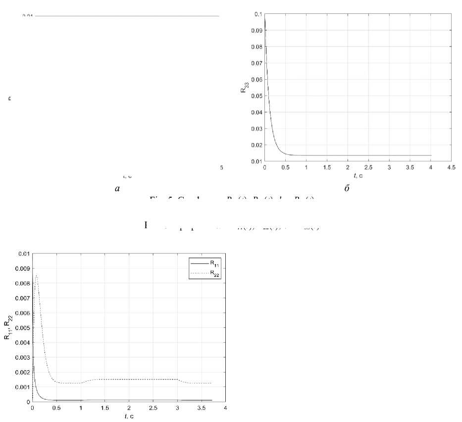
Fig. 5 shows the diagonal elements of the covariance matrix for R 11 (0) = 0.01; R 22 (0) = 0.001; R 33 (0) = 0.1; B z = diag (0.0001, 0,18). It can be seen that over time they come to steady-state values. Simulations were also carried out at different noise levels. The Kalman filter fulfills them successfully.
Since the measurement noise does not have a strong impact on the control, it was proposed to periodically turn off the sensors operation and determine the current position by mathematical modeling to save energy. This made it possible to successfully solve the control problem at lower energy costs. When the sensors are turned off, no energy is expended for their operation and data transmission.
Fig. 3. Graphs: a – l ( t ); b – V ( t )
Рис. 3. Графики: a – l ( t ); б – V ( t )
Fig. 4. Graphs: a – I ( t ); b – P ( t )
Рис. 4. Графики: a – I ( t ); б – P ( t )
а
11’ 22
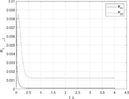
Fig. 5. Graphs: a – R 11 ( t ), R 22 ( t ); b – R 33 ( t )
Рис. 5. Графики: а – R 11 ( t ), R 22 ( t ); б – R 33 ( t )
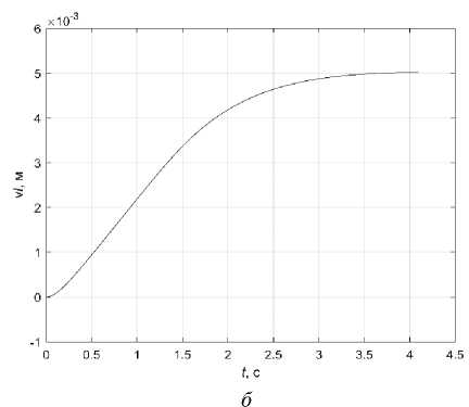
Fig. 6. Graphs: a – R 11 ( t ), R 22 ( t ); b – l ( t )
Рис. 6. Графики: а – R 11 ( t ), R 22 ( t ); б – l ( t )
Fig. 6, a shows the graphs of R 11 ( t ) and R 22 ( t ) when measurements are turned off for 1 to 3 seconds. Fig. 6, b shows the estimated value l ( t ). The elements of the covariance matrix come to a steady-state value when observed. At the measurement cut-off interval at B - 1 = 0 and B - 1 = 0 the values of the estimates and R 11 ( t ), R 22 ( t ) are calculated using the filter in the forecast mode.
When measurements are turned on for 3 s, the Kalman filter brings the estimate to the optimal value by 3.2 s. The mathematical expectation of noise is equal to zero, therefore when measurements are turned off there are no significant differences in the assessment of the measured values. The presence of external disturbances is critical, since during the time the sensors are turned off, the mathematical model can leave the state of the real system. In view of the fact that the control process for the problem under consideration takes t f = 4 s, it is important to include measurements when approaching the final values which will allow to assess the state of the system and, if necessary, correct the control. In this case, it is sufficient to measure the length of the piezo actuator l extension; turning on the voltage measurement sensor U e0 = 0 slightly increases the accuracy of the problem solution.
Estimation errors Δ l and Δ U e during the Kalman filter operation tend to zero over time. In the presence of external disturbanses, these errors have a mathematical expectation equal to zero and a variance that does not exceed the variance of disturbances.
Conclusion
To solve the control problem, algorithms were also applied based on the Pontryagin maximum principle using the numerical methods of Newton, Krylov-Chernousko, and the algorithm for correcting the control structure parameters [12; 23; 27]. The sequential optimization algorithm allowed reducing energy costs for control by 12 %. The use of the PID control structure increased the cost of electricity by 27 % compared to the proposed algorithm [28] in the presence of readjustment.
As can be seen, numerical modeling has confirmed the possibility of solving the optimal control problem of the piezo actuator stochastic model for the LTR radio-reflective net adjustment using incomplete data while applying the separation principle. Interval measurements turn off allows the reduction of energy consumption for sensor power supply and measurement processing. In this case longer sensor activation at the terminal time leads to a more accurate fulfillment of the terminal conditions. Therefore, an additional problem of optimizing observation intervals arises in order to minimize energy costs with high-precision fulfillment of terminal conditions [29].
The research presented was reported at the XXII International Scientific Conference "System Analysis, Control and Navigation" [30].
References Solution of the filtration problem with the optimal adjustment of the radio-reflecting net of a transformable reflector
- Vovasov V. E., Betanov V. V., Gerko S. A. [Calibration technique of navigation glonass receiver using combinations of dual-frequency pseudorange measurements]. Aerospace MAI Journal. 2014, Vol. 21, No. 5, P. 137–144 (In Russ.).
- Fyodorov A. V., Hoang Vu. T. [Software package for motion control algorithms design of service module in geostationary orbit]. Aerospace MAI Journal. 2020, Vol. 27, No. 4, P. 192–205 (In Russ.).
- Каzаntsеv Z. А. [Deployment concept mechanical system of a radar antenna for space purposes]. Siberian Journal of Science and Technology. 2017, Vol. 18, No. 4. P. 858–867 (In Russ.).
- Xuelin D., Jingli D., Hong B., Guohui S. Deployment analysis of deployable antennas considering cable net and truss flexibility. Aerospace Science and Technology. 2018, Vol. 82–83, P. 557–565.
- Wang H. Multifrequency Spaceborne Deployable Radiometer Antenna Designs. IEEE Aerospace and electronic systems magazine. 2020. Vol. 35, No. 5, P. 28–35.
- Deployable reflector system for satellite applications, in: 2005 SBMO / M. Terada, N. Bludworth, J. Moore et al. IEEE MTT-S International Conference on Microwave and Optoelectronics. Brazil. 2005. P. 647–656.
- Li T. Deployment analysis and control of deployable space antenna. Aerospace Science and Technology. 2012, Vol. 18, No. 1, P. 42–47.
- Reznik S. V., Chubanov D. E. [Modeling the dynamics of the deployment of a large-sized transformable reflector of a space antenna made of composite material]. RUDN Journal of Engineering Researches. 2018, Vol. 19, No. 4, P. 411–425 (In Russ.).
- Bel’kov A. V., Belov S. V., Zhukov A. P., Pavlov M. S., Ponomarev S. V., Kuznecov S. A. [Method for calculation of the stress-strain state for cable-membrane space reflector structures]. Vestn. Tomsk. Gos. Univ. Mat. Mekh. 2019, No. 62, P. 5–18 (In Russ.).
- Berns V. A., Levin V. E., Krasnorutsky D. A., Marinin D. A., Zhukov E. P., Malenkova V. V., Lakiza P. A. Development of a calculation and experimental method for modal analysis of large transformable space structures. Spacecrafts & Technologies. 2018, Vol. 2, No. 3, P. 125–133.
- Kabanov S. A., Zimin B. A., Mitin F. V. [Development and Research of Mathematical Models of Deployment of Mobole Parts of Transformable Space Construction. Part I]. Mekhatronika, Avtomatizatsiya, Upravlenie. 2020, Vol. 21, No. 1, P. 51–64 (In Russ.).
- Kabanov S. A., Zimin B. A., Mitin F. V. [Development and Research of Mathematical Models of Deployment of Mobole Parts of Transformable Space Construction. P. II]. Mekhatronika, Avtomatizatsiya, Upravlenie. 2020, Vol. 21, No. 2, P. 117–128 (In Russ.).
- Kabanov S. A., Mitin F. V. Optimization of the stages of deploying a large-sized space-based reflector. Acta Astronautica, Special Issue on 6th SFS 2019, 2020, No. 176, P. 717–724.
- Huang H., Cheng Q., Zheng L., Yang Y. Development for petal-type deployable solid-surface reflector by uniaxial rotation mechanism. Acta Astronautica. 2021, No. 178, P. 511–521.
- Taygin V. B., Lopatin А. V. [Method of achievement the high accuracy of the shape of reflectors of mirror antennas of spacecraft]. Spacecrafts & Technologies. 2019, Vol. 3, No. 4, P. 200–208 (In Russ.).
- Kalabegashvili G. I., Bikeev E. V., Mathylenko M. G. [Determination of the minimal reflecting surface points number required for assessment of large-size transformable antenna pattern deviation]. Siberian Journal of Science and Technology. 2018, Vol. 19, No. 1, P. 66–75 (In Russ.).
- Ishkov V. N. [Solar geoeffective phenomena: Action on the near-earth outer space and the possibility of the forecast]. Slozhnye sistemy. 2012, No. 4 (5), P. 21–41 (In Russ.).
- Mihalyaev B. B., Derteev S. B., Lagaev I. Y., Osmonov T. T. [Vliyanie solnechnoj aktivnosti na magnitosferu Zemli]. Aktual’nye problemy sovremennoj fiziki i matematiki. trudy. 2017, P. 92–97 (In Russ.).
- Panich A. E. P’ezokeramicheskie aktyuatory [Piezoceramic actuators]. Rostov-na-Donu, YUFU Publ., 2008, 159 p.
- PIN-50-U-4/20-DKh – preobrazovatel’ izmeritel’nyy postoyannogo i peremennogo napryazheniya [PIN-50-U-4/20-DX – DC and AC voltage Measuring Converter]. Available at: https://www.electronpribor.ru/catalog/850/pin-50-u-420-dh.htm (accessed: 10.10.2021).
- 3D skanery RangeVision [3D Scanners Range Vision]. Available at: https://printer-plotter.ru/3d-oborudovanie/3d-scanners/rangevision/?yclid=5975775935832053836 (accessed: 10.10.2021).
- Kabanov S. A., Mitin F. V., Krivushov A. I., Ulybushev E. A. Control of a piezo actuator to adjust reflrctive surface of the space-based reflector. Russian Aeronautics (Iz. VUZ). 2018, Vol. 61, No. 4, P. 629–635.
- Spravochnik po teorii avtomaticheskogo upravlenija. Pod red. A. A. Krasovskogo [Handbook on the theory of automatic control. Ed. by A. A. Krasovskij]. Moscow, Nauka Publ., 1987, 712 p.
- Kabanov S. A. Optimizaciya dinamiki sistem pri deystvii vozmushcheniy [Optimization of the dynamics of systems under the action of disturbances]. Moscow, Fizmatlit Publ., 2008, 200 p.
- Kabanov D. S. [Optimal control of a nuclear reactor taking into account random disturbances]. Journal of instrument engineering. 2009, No. 5, P. 27–30 (In Russ.).
- Kabanov S. A. Upravlenie sistemami na prognoziruyushchih modelyah [Control systems based on predictive model]. SPb., SPbGU Publ., 1997, 200 p.
- Kabanov S. A., Mitin F. V. Optimization of the Processes of Deploymentand Shape Generationfor a Transformable Space-Based Reflector. Journal of Computer and Systems Sciences International. 2021, Vol. 60, No. 2, P. 283–302.
- Kabanov S. A., Mitin F. V. [Optimal control for piezo actuator for setting the shape of the radio-reflecting network]. Journal of Instrument Engineering. 2021, Vol. 64, No. 3, P. 183–191 (In Russ.).
- Malyshev V. V., Krasil’shchikov M. N., Karlov V. I. Optimizaciya nablyudeniya i upravleniya letatel’nyh apparatov [Optimization of surveillance and control of aircraft]. Moscow, Mashinostroenie Publ., 1989, 312 p.
- Kabanov S. A., Mitin F. V., Shevchik A. A. [Solution of the filtration problem with the optimal adjustment of the radio reflecting net of a transformable reflector]. Sistemnyy analiz, upravlenie i navigaciya. Moscow, Izd-vo MAI Publ., 2021, P. 170–171.
