Современный нагревный стенд для исследования ионосферы средних широт

Автор: Васильев Р.В., Сетов А.Г., Фролов В.Л., Ратовский К.Г., Белецкий А.Б., Ойнац А.В., Ясюкевич Ю.В., Медведев А.В.
Журнал: Солнечно-земная физика @solnechno-zemnaya-fizika
Статья в выпуске: 2 т.6, 2020 года.
Бесплатный доступ
Создание новых устройств для проведения исследований в области физики верхней атмосферы и околоземного космического пространства, на которых можно проводить контролируемые эксперименты по модификации ионосферы мощным коротковолновым излучением, является актуальной задачей сегодняшнего дня в области солнечно-земной физики, прогнозирования космической погоды, эксплуатации спутниковых группировок в околоземном космическом пространстве, радиосвязи и радиолокации. В работе описывается современный нагревный стенд, разрабатываемый в рамках Национального гелиогеофизического комплекса Российской академии наук, приводится обзор задач, которые можно решать с его помощью, обсуждаются его основные технические характеристики, и дается описание окружающей стенд наблюдательной инфраструктуры. В работе обосновывается перспективность создания в средних широтах Восточной Сибири нагревного стенда, который может излучать в частотном диапазоне 2.5-6.0 МГц с эффективной мощностью порядка нескольких сотен мегаватт. Важно, что стенд будет находиться в окружении многофункциональных инструментов, таких как современный радар некогерентного рассеяния, мезосферный и стратосферный лидар, а также набора современных оптических и радиофизических наблюдательных систем, которые могут обеспечить широкие возможности диагностики искусственных плазменных возмущений и искусственных образований оптического свечения верхней атмосферы.
Радиофизика, ионосфера, нагревный стенд, солнечно-земная физика, космическая погода
Короткий адрес: https://sciup.org/142224299
IDR: 142224299 | УДК: 533.951, | DOI: 10.12737/szf-62202005
Modern heating facility for research into the mid-latitude ionosphere
The development of new devices for research in physics of the upper atmosphere and near-Earth space, which can be used to carry out controlled experiments on the modification of the ionosphere by powerful short-wave radiation, is an urgent task of modern solar-terrestrial physics, space weather, operation of satellite constellations in near-Earth space, radio communications, and radar. The paper describes a modern heating facility, created within the framework of the National Heliogeophysical Complex of the Russian Academy of Sciences. We review the tasks facing the heater, discuss its main technical characteristics, and describe the capability of the observational infrastructure surrounding the heating facility. The paper justifies the long-term benefits of the development of a heating facility at middle latitudes of Eastern Siberia, which can radiate in a frequency range 2.5-6.0 MHz with an effective power of the order of several hundred megawatts. It is important that the heater will be surrounded by such multifunctional instruments as the modern incoherent scatter radar, mesostratospheric lidar, observational systems that can provide a wide range of possibilities for diagnosing artificial plasma disturbances and artificial airglow structures.
Текст научной статьи Современный нагревный стенд для исследования ионосферы средних широт
Study of features of the interaction between powerful high-frequency (HF) radiation and Earth's ionosphere deals with the areas of plasma and solar-terrestrial physics most actively developed in recent decades. The history of study of major effects on the ionosphere dates back to the 1960–70s [Shlyuger, 1974; Gurevich, 2007]. The growing interest in this subject is due to a variety of possible applications related to plasma heating by powerful HF radiation. A principal point here is that the interaction between powerful electromagnetic waves and plasma is accompanied by the development of a number of fundamental nonlinear phenomena. Among them are the development of parametric plasma instabilities and excitation of strong plasma turbulence; generation of artificial ionospheric irregularities with scales from a meter to tens of kilometers across geomagnetic field lines; modification of the plasma density profile under the action of light and heat pressure; acceleration of electrons to superthermal energies and generation of optical radiation through impact excitation of atoms of the neutral atmospheric component by the accelerated electrons; generation of secondary electromagnetic radiation in regions with well-developed plasma turbulence; excitation of electric fields and currents in a plasma with developed artificial ionospheric turbulence (AIT); precipitation of energetic electrons from Earth's radiation belt induced by heating, and other processes. All this leads to total strong heating of plasma near the height of reflection of a powerful radio wave when the plasma electron temperature can increase several times [Gurevich, 2007]. Today, the ionosphere may be regarded as a natural plasma laboratory that can make studies using AIT, generated through plasma heating by powerful radio waves from specially constructed ground-based radio facilities — heaters [Erukhimov, Genkin, 1992; Perkins et al., 1974; Gurevich, 1978; Stubbe, Hagfors, 1997; Streltsov et al., 2018].
Capacities of currently available radio stations of various purposes are sufficient to produce significant changes in ionospheric plasma characteristics. This
This is an open access article under the CC BY-NC-ND license
means that the ionosphere is now nearly always excited and we must take this fact into account when studying processes occurring in it.
Modifications of Earth's ionosphere by powerful radio waves at different times were studied using more than ten different heating facilities [Frolov, 2017] . Today, the studies are carried out using four heating facilities [Streltsov et al., 2018] : two at high latitudes (EISCAT-Heating in Northern Norway and HAARP in Alaska, the USA); one at middle latitudes (SURA, Russia), and one at low latitudes (Arecibo, Puerto Rico, the USA). Targeted studies of the interaction of powerful HF radiation with plasma, which have been conducted in Russia, the USA, and Western European countries for more than 50 years, have revealed the basic laws of the development of AIT and have enabled the construction of empirical and theoretical models of generation of its various components. The main results of these studies are reported in the monographs [Frolov, 2017; Gurevich, 1978] , reviews [Gurevich, 2007; Grach et al., 2016; Erukhimov et al., 1987; Stubbe, 1996; Stubbe, Hagfors, 1997; Leyser, 2001; Streltsov et al., 2018] , special issues of journals [Izvestiya vuzov. Radiofizika. 1999, 2005, 2008, 2012; J. Geophys. Res. 1970; J. Atmos. Terr. Phys. 1982, 1985, 1997] , and in references therein.
The scientific problems facing the heaters in radiophysics, studies of Earth's upper atmosphere and space weather, magnetospheric and radiation belt physics, as well as in laser induced synthesis are described in [Streltsov et al., 2018] . Among the phenomena that can be investigated with the heater at middle latitudes are the following:
-
• radiophysics and radio wave propagation in the ionosphere:
-
– production of artificial plasma sheets and related effects of HF and VHF radio wave propagation;
-
– generation of VLF, ULF, and ELF radio waves, and study of characteristics of their propagation;
-
– generation of artificial plasma irregularities and their influence on propagation of radio waves of different ranges, and satellite communication and navigation systems;
-
– generation and study of artificial ionospheric radio emission;
-
– generation and study of the Luxembourg-Gorky effect;
– short-wave radar of the atmosphere, near-Earth space, and near space.
-
• The upper atmosphere, the mesosphere, the thermosphere, and the mesosphere-thermosphere coupling:
-
– generation of artificial periodic irregularities and study of the behavior of the neutral component density and its temperature in the D, E, and F regions of the ionosphere;
-
– generation of artificial optical airglow and artificial ionization of the atmosphere at ionospheric heights;
-
– electron acceleration in regions with strongly enhanced Langmuir and upper hybrid turbulences induced by a powerful radio wave;
-
– thermosphere heating and generation of wave
disturbances of the neutral component density (traveling ionospheric disturbances, acoustic-gravity waves, and infrasound);
-
– modification of the sporadic E layer.
-
• Space weather:
– substorms and their possible triggers;
– trigger effects of chemical reactions caused by high electron temperature and density irregularities;
– atmospheric gravity waves induced by high-temperature ion fluxes.
-
• Magnetospheric and radiation belt physics:
– make use of virtual antennas for injecting VLF/ULF/ ELF-waves into the magnetosphere and for influencing Earth's radiation belts;
– change and study of conditions of propagation, decay, transformation of whistler modes and Alfvén waves;
– formation of artificial channels and waveguides in plasma;
– change of the pitch angle of particles trapped in the radiation belts by whistlers, Alfvén waves, and electromagnetic ion-cyclotron waves;
– excitation of magnetospheric resonators and study of ionospheric and magnetospheric waveguides.
-
• Laser fusion:
– nonlinear experiments in an unbounded plasma (in a region without bounding walls of conducting material);
– generation and study of parametric instabilities in terms of physics of nonlinear processes in plasma.
Despite the considerable progress achieved to date, the study of the nature and features of these phenomena in some areas cannot be considered fully complete today. It is therefore important now to design a new heating facility surrounded by a wide range of various modern diagnostic facilities, which can solve problems facing researchers under fairly quiet (stable) geomagnetic conditions intrinsic to the mid-latitude ionosphere.
As part of the National Heliogeophysical Complex (NHC) of the Russian Academy of Sciences, a new heating facility — Irkutsk short-wave antenna array with active transmitters (IKAR-AI) — is being developed at middle latitudes (52.4° N, 103.6° E). This heater is designed for studies related to the impact of powerful HF radiation on ionospheric plasma, and provides the solution of the above problems. All the necessary diagnostic instruments are available in the scientific infrastructure of ISTP SB RAS or will be developed under NHC RAS. In addition to the heating facility, the research complex will include state-of-the-art facilities for atmosphere diagnostics such as an incoherent scatter radar, a mesostratospheric lidar, coherent short-wave radars of SuperDARN type; allsky cameras; diffraction spectrometers and Fabry— Perot interferometers operating in spectral regions of the main atmospheric emissions; a network of vertical, oblique, and backscatter ionosondes; a network of receivers of signals from global navigation satellite systems. This complex will have unique research potential and provide a high level of scientific results. This will enable us to conduct active experiments on atmospheric and ionospheric processes, to successfully solve topical problems of nonlinear plasma physics, to study Earth's upper atmosphere, near-Earth space, as well as to address issues related to space weather.
cuss its main technical characteristics and capabilities, as well as its position in the existing and developed infrastructure of scientific instruments of ISTP SB RAS and NHC RAS.
The purpose of this paper is to present the possible architecture of the future heating facility IKAR-AI, to dis-
Table 1
Characteristics of modern heating facilities
|
Arecibo (USA) |
SURA (Russia) |
Tromsø (Northern Norway) |
HAARP (USA) |
IKAR-AI (Russia) |
|
|
Geographic coordinates |
18.34° N 66.75° W |
56.15° N 46.1° E |
69.6° N 19.2° E |
62.39° N 145.15° W |
52.42° N 103.65° E |
|
Frequency range MHz |
|
4.3–9.5 |
|
2.8–10 |
2.5–6.0 |
|
Generated power, MW |
0.6 |
0.75 |
1.0 |
3.6 |
0.9 |
|
Antenna gain, dB |
a) 22 b) 25.5 |
19–24 |
a) 22–25 b) 28–31 |
21–31 |
21–27 |
|
Effective radiation power, MW |
|
100–280 |
a) 180–340 b) 630–1260 |
400–3600 |
120–470 |
|
Polarization |
O, X or linear |
O or X |
O or X |
O, X or linear |
O, X or linear |
|
Beam pattern radiation |
vertical |
scanning in geomagnetic plane (to 40° from vertical) |
scanning in geomagnetic plane (to 20° from vertical) |
scanning in space (to 30° from vertical) |
scanning in space (to 30º from vertical) |
|
Inclination of magnetic field |
42° |
19° |
12° |
15° |
17° |
-
1. MAIN TECHNICAL CHARACTERISTICS
OF IKAR-AI
It is obvious that to determine characteristics of the new heating facility we should build on currently available devices of this type. Brief characteristics of the heaters in current operation are listed in Table 1 (see [Frolov, 2017; Streltsov et al., 2018] ). To select the optimal characteristics of IKAR-AI, we should take into account many aspects of generation of various AIT components at middle latitudes. Here, we can entirely rely on the results of the studies of AIT properties, carried out with the midlatitude heater SURA, which are discussed in detail in [Frolov, 2017] and summarized below.
1.1. Selection of effective radiation power
AIT in the F2-region of the mid-latitude ionosphere is generated most effectively by O-polarization radio waves, which are radiated from Earth's surface vertically or almost vertically. The development of the observed phenomena is generally has a threshold character in terms of effective radiation power of excitation wave (EW). The effective radiation power is defined as P eff = P 0 G , where P 0 is the total HF power generated by transmitters of the heater; G is the gain of the heater's antenna array for its main lobe with respect to an isotropic radiator.
At the first stage of AIT development near the height of reflection of a powerful radio wave in the time interval 1– 10 ms, a striction parametric instability arises due to the electromagnetic wave scattering to Langmuir plasma oscillations by plasma ions with the subsequent formation of the plasma wave spectrum. This is a threshold effect with Peff thresh≈2÷4 MW radiated at EW frequencies f0≈4÷6 MHz under evening and night quiet ionospheric conditions at heights above 200 km. The value of Peff thresh increases with increasing EW frequency and can significantly increase with geomagnetic disturbance of the ionosphere, e.g., due to increasing absorption of radio waves in the lower layers of the ionosphere and the presence of steep plasma density gradients in the region of instability. When the striction parametric instability develops, up to 90 % of EW power is absorbed in the ionosphere near the height of its reflection for a few milliseconds. At the same time, the Langmuir turbulence spectrum is formed, background plasma electrons accelerate up to suprathermal energies, thus generating the artificial airglow and additional atmosphere ionization. We can also observe the excitation of small-scale artificial ionospheric irregularities with scales l⊥ ≈2÷3 m across geomagnetic field lines. These irregularities may serve as initial at the next stage of AIT development — the stage of development of thermal (resonance) parametric instability. At a high level of development of the striction parametric instability, there may be a transition to the excitation mode of strong Langmuir turbulence.
At the second stage of AIT development within 0.3– 10 s after the start of the F2-region modification by powerful O-polarization radio waves at the height of upper hybrid resonance (1–5 km below the height of EW reflection), the thermal (resonance) parametric instability (TPI or RI) is excited. TPI develops due to the electromagnetic wave scattering by small-scale artificial ionospheric irregularities with l⊥≈1÷50 m into upper hybrid plasma oscillations. The threshold power of the TPI development Peff thresh≈0.5–1 MW for f0≈4–6 MHz under quiet evening and night ionospheric conditions during EW reflection at heights above 200 km. If ionospheric conditions get worse, Peff thresh (TPI) increases. As TPI develops, almost all the EW energy is absorbed in the ionosphere (anomalous damping effect). A distinctive feature of the TPI development is generation of intense small-scale artificial irregularities in a wide range of scales l⊥ across geomagnetic field lines from 1 m to 30–100 m, which cause intense aspect scattering of radio waves. At the TPI stage, background plasma electrons also accelerate to superthermal energies. The excited upper hybrid plasma waves with small-scale irregularities are involved in the formation of thermal components of artificial ionospheric radiation.
At the third stage of the AIT development within 3– 60 s after the start of the F2-region modification by powerful radio waves, a thermal self-focusing instability appears and medium-scale artificial ionospheric irregularities of plasma density with l ⊥ ≈0.2–1.0 km are generated near the height of EW reflection. This instability develops for high-power radio waves of both polarizations, but more intensively for O-polarization waves due to more intense (resonance) plasma heating. The threshold power of self-focusing instability is 3–5 MW under evening and night ionospheric conditions and greatly depends on geomagnetic conditions. Plasma density irregularities of kilometer scales are thought to be generated due to the enhancement of natural irregularities.
Particularly noteworthy is the influence of the effect of “magnetic zenith” on the TPI development and selffocusing instability when the intensity of small-scale and medium-scale artificial irregularities increases by several decibels. This occurs provided that a powerful O-polarization wave at the level of upper hybrid resonance propagates along geomagnetic field lines, which ensures its more effective interaction with plasma [Gurevich, 2007; Streltsov et al., 2018] . For this purpose, at the SURA latitude an oblique EW radiation is used with angles 10°–16° from the vertical to the geomagnetic south. The second factor determining the large increase in the AIT intensity and its properties is the turbulence generation under conditions in which the EW frequency is approximately equal to the doubled electron gyrofrequency in the region of interaction of a powerful O-polarization radio wave with plasma [Streltsov et al., 2018; Kosch et al., 2007] .
At all stages of the interaction of EW with ionospheric plasma, it is heated and the plasma density profile changes in the region bounded by the width of the main lobe of the beam pattern (BP) of the heater's antenna. In this case, the electron temperature near the magnetic zenith may increase 2–3 times as compared to the background value, the plasma density decreasing by 30–40 % near the height of EW reflection. Such a cavity with decreased plasma density behaves like a focusing lens. However, the presence of intense artificial irregularities of different scales in it during modification of the ionosphere by powerful HF radio waves severely impairs its focusing properties, which are pronounced only after switching off EW when a smaller-scale portion of the spectrum of the irregularities relaxes.
A feature of the modification of the dayside ionosphere is the formation of a region with increased plasma density at heights 130–170 km due to its heating and subsequent disruption of the ionization-recombination balance. This region has defocusing properties. A decrease due to this defocusing can be as great as 20 dB at P eff ≈100 MW. Along with the regular absorption of powerful radio waves in the ionosphere, an EW intensity decrease at the level of its reflection can reach 30 dB, therefore the EW intensity at the height of its reflection may be lower than its threshold values for the development of the aforesaid instabilities. Furthermore, under daytime conditions the height of reflection of a powerful radio wave is generally within 200 km, below which threshold powers of the above instabilities increase sharply due to a significant increase in the electronneutral collision frequency. The presence of the ionospheric F1 layer also affects the powerful radio waveplasma interaction. The AIT intensity in the upper ionosphere under daytime conditions of its modification is therefore generally low. An exception at middle latitudes is winter months in the absence of geomagnetic disturbances when regular absorption of powerful radio waves in the lower ionosphere may remain low.
In summary, we may conclude that for the desired (5÷10)-fold excess of thresholds of development of instabilities in evening and nighttime measurements it is sufficient to have a heater with an effective radiation power P eff ≈10÷20 MW. It is precisely these powers that were inherent in the Arecibo heater (first version), heating facilities in Zimenki, Monchegorsk, and Gissar, where in the 1970s most main results of heating experiments were obtained. In view of changing ionospheric conditions and expansion of experiments to morning and early evening hours, it is necessary to transmit a more powerful EW. In this case, the 50–200 MW power (SURA and EISCAT-Heating) is generally sufficient. These powers are sufficient to measure ionospheric parameters at heights from D- to F2-region, using the method of artificial periodic irregularities [Belikovich et al., 1999] , as well as to measure characteristics of the effects of cross-modulation and generation of VLF–ELF waves at heights of the lower ionosphere [Belyaev et al., 1987; Stubbe et al., 1981; Ginsburg, 1967] .
In concluding this section, we should note the following. Recently performed experiments have enabled the discovery and study of such phenomena as generation of additional ionospheric layers [Mishin et al., 2016], stimulated precipitation of energetic electrons from Earth's radiation belts [Frolov et al., 2019], generation of wave disturbances at ionospheric heights during periodic heating of ionospheric plasma [Chernogor et al., 2019; Mishin et al., 2012], generation of channels (ducts) with increased plasma density at heights of the outer ionosphere [Frolov et al., 2016; Vartanyan et al., 2012], generation of electric currents at ionospheric heights during AIT development [Lukianova et al., 2019]. All these phenomena were observed when the effective power of EW was not lower than 50 MW. Such high powers are required for the generation of artificial optical glow, experiments on modification of the magnetosphere and magneto-conjugate ionospheric region, and the use of the heater as a powerful shortwave locator or partial reflection radar to radar the atmosphere, near-Earth space, and near space. In view of the foregoing and variations in a wide range of ionospheric conditions, IKAR-AI should have an effective radiation power no lower than 100–200 MW.
1.2. Selection of a frequency radiation band
The frequency band of existing heaters is within 2.7–10 MHz. When selecting a frequency band for IKAR-AI, we should take into account the following. On the one hand, the wider the band, the more choices of the optimal frequency for measurements in different geophysical conditions. On the other hand, the narrower the band, the simpler the design of the transmitting antenna of the heater and the cheaper the complex developed. Obviously, the main criterion for selecting the frequency band of the heater is the range of variation in the F2-layer critical frequency ( f o F2) within 24 hours in different seasons at different solar and geomagnetic activity levels, as well as the capability of operation at EW frequencies near the second harmonic of the electron gyrofrequency.
Let us consider the capability of operation of the heating facility at middle latitudes (~52°) in Eastern Siberia. For this purpose, we estimate the probability of a certain value of the F2-layer critical frequency at a given time. For IKAR-AI to be able to operate at the lowest levels of ionization of the upper atmosphere, it is necessary to assess the probability for solar minimum. Using the Irkutsk Ionosonde DPS-4 database, we have calculated statistical distributions of f o F2 and H m F2 at different times UT for 2016–2019 (Figure 1). This ionospheric data in view of the fact that the F2-layer modification is most effective in evening and night time, and the lower ionosphere modification under daytime conditions is more effective at lower EW frequencies allows us to identify the band of operating frequencies of the heater as 2.5–6.0 MHz.
Note that this band makes it possible to heat the ionosphere at frequencies close to electron gyrofrequency harmonics from the second to the fourth (1.4–1.5 MHz for the intended location of the heater). It is important that it covers frequencies close to the second electron gyrofrequency harmonic, where the modification of the upper atmosphere has its own important specific features and advantages associated with dispersion properties of electromagnetic waves in a magnetoactive plasma. With EW frequencies f 0 ≈2 f SU , the high intensity of generated AIT is achieved at much lower powers of its radiation than in the frequency band 4–6 MHz [Streltsov et al., 2018] . Properties of the interaction of powerful electromagnetic waves with magnetoactive plasma when conditions of multiple gyroharmonic resonance hold (as well as under conditions of double resonance) when the EW frequency in the EW-plasma interaction region is simultaneously equal to the upper hybrid resonance frequency and gyroharmonic frequency are still of great interest and warrant further study. This mainly concerns the acceleration of electrons to superthermal energies and the optical glow and additional ionization they cause [Grach, 1999; Grach et al., 2014; Kosch et al., 2002; Grach et al., 2004; Pedersen et al., 2009, 2011a, b; Sergeev et al., 2013] .
In gyroharmonic experiments, it is of great interest to monitor the behavior of artificial ionospheric irregularities of different scales with simultaneous use of radiophysical and optical recorders. Furthermore, in the case of recording of artificial airglow in several spatially separated sites it becomes possible to assess spatial characteristics of a luminous region; and with the aid of a suitable model to determine parameters of three-dimensional distribution of excited oxygen atoms. The measurement of the vertical brightness profile of the artificial airglow is also of interest as a method for studying energy characteristics of superthermal electrons and for experimental verification of theoretical models of acceleration and depth of penetration of accelerated electrons upward and downward from the turbulent layer [Shindin et al., 2018] .
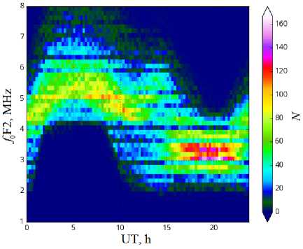
Figure 1 . Statistical distribution (histograms) of f oF2 (left) and H mF2 (right) of the F2-layer peak at different times UT over the intended location of the future heating facility (left). Color indicates the number of events for a certain characteristic at a given time
Thus, the above analysis of ionospheric data for the intended location of IKAR-AI and the list of research tasks, as well as the experience in working with SURA have shown that in most cases to meet the goals it suffices to have a chance to radiate EW in the frequency band 2.5–6.0 MHz.
1.3. Technical configuration of the heater
As mentioned above, at middle latitudes O-polarization waves due to the possibility of their resonance interaction with plasma in vertical or nearly vertical radiation lead to a more intense generation of AIT than X-polarization waves. Nevertheless, among other heater characteristics needed for basic and applied research it is necessary to have a possibility to radiate radio waves of both O- and X-polarizations (linear polarization waves are also desirable). It is also necessary to explore the possibility of using IKAR-AI as a short-wave radar or partial reflection radar with a beam tilt angle up to 40–50° from vertical in any direction; the capability of its operation in, at least, two EW frequencies each radiated with its own polarization, power, time mode, as well as the possibility of using the entire array or its parts in the receiving mode.
In accordance with the requirements imposed on the heater, IKAR-AI is assumed to be an active phased antenna array consisting of crossed broadband dipole antennas, each dipole connected to a separate solid-state transmitter with an output power of ~5 kW. To minimize losses in matching elements and feeders, we use a module design of the antenna array when two transmitters are located close to a pair of crossed dipoles, forming one module of the heater. All heater modules are controlled by a common synchronizing and phasing system, which sets the phase shift of radiation from each radiating element in such a way as to form a narrow beam of short-wave radiation in a given direction. An electronic system is required that can control the position of the beam in space, as well as to choose power, frequency, polarization, and time mode of EW radiation independently for each module. Control signals for each module are formed by digital synthesizers, synchronized by a uniform standard of frequency and time. The heater operation modes are controlled via an optic-fiber network to minimize the interference from radiating elements and the level of spurious feedbacks. We should also provide the possibility of applying each element of the antenna array in the reception mode with the corresponding system for detecting and processing received signals. Such a system will greatly extend the capability of the active phased array antenna and enable IKAR-AI to function effectively as a short-wave radar or a partial reflection radar.
As follows from the above analysis, to provide the effective radiation power of 200 MW in the frequency band 2.5–6.0 MHz, the IKAR-AI architecture must include an antenna array with G =200÷400 and correspondingly 50–100 units with two 5-kilowatt RF generators each. These basic figures, along with the requirements for the heater in terms of possibilities of its use to address various problems, are the foundation for the development of its structure.
2. SIMULATION OFANTENNA ARRAY
For successful operation of the heater, it is necessary to ensure a high effective radiated power throughout the operating frequency band 2.5–6.0 MHz, i.e. with 2.4 overlap. Construction of a unified antenna array for the entire band is a challenge because in this case we would have to use large complex emitters with their suspension height that is not always optimal.
Table 2
Characteristics of beam patterns of two configurations of the antenna field
|
Configuration |
Antenna field size, m2 |
Band, MHz |
Beamwidth, deg. |
Antenna gain G , dB |
Middle level of side lobes, dB |
Beam efficiency |
|
Rectangular, 64 elements |
78 400 |
2.5–3.5 |
17.9/14.4 |
20.5/22.2 |
–26.8/–25.8 |
0.93/0.87 |
|
4.0–6.0 |
11.8/7.9 |
24/27 |
–27.3/–27.3 |
0.88/0.79 |
||
|
Hexagonal, 61 elements |
66 500 |
2.5–3.5 |
20.2/16.2 |
19.7/21.4 |
–27.7 / –26.4 |
0.95 / 0.9 |
|
4.0–6.0 |
13.2/8.8 |
23.2/26.2 |
–27.9 / –27.7 |
0.9 / 0.83 |
||
|
Ring, 36 elements in each subband |
320 000 |
2.5–3.5 |
9.5 / 7.5 |
25.2/24.3 |
–27.4/–22.7 |
0.76/0.37 |
|
4.0–6.0 |
9.3 / 6.1 |
24.2/23.5 |
–23.2/–19.9 |
0.48/0.185 |
It is therefore expected that the operating band will be separated into two subbands and two different sets of antennas will be deployed. Under such conditions, it is optimal to have two separate antenna arrays: one for 2.5–3.5 MHz and the other for 4–6 MHz. In this case, the radiating dipoles will have a relatively simple configuration with an optimal suspension height, and two antenna arrays will enable us to operate near the second (2.5–3.5 MHz), third, and fourth (4–6 MHz) electron gyrofrequency harmonics. Below are the results of sim- ulation of antennas of two types: 1) development of one array with special broadband antennas; 2) separation of the band into two subbands and creation of two antenna arrays, each working in its own subband. As a version with wideband antennas, we consider two arrays — rectangular and hexagonal. For the dual-band version, we analyze the ring array with sets of two rings for each subband (4–6 MHz and 2.5–3.5 MHz) with separately located dipoles in the center of the rings to reduce the level of side lobes. Characteristics of the antenna fields can vary greatly depending on the number of array elements and their mutual arrangement. Special attention should be given to the antenna gain G and the effective power Peff of the heater as the main parameters determining the EW power flux density in the heating region. These configurations differ significantly, for the comparison we therefore take approximately the same number of crossed dipole antennas (60–65) as the main parameter determining the final cost of the phased antenna array with two separate 5 kW transmitters for each element (one transmitter for each polarization of crossed dipole).
The simulation involves calculating BP of the phased array for different configurations; BPs of the antenna array are calculated taking into account the ground effect, but ignoring the interference of elements. Special attention is paid to the scanning sector of the heater — when the beam tilts by 30° from normal, diffraction lobes (BP lobes equal to the main lobe in magnitude) should not appear. As an individual array element we utilize a crossed dipole with suspension height and length equal to 25 m for the lower operating band
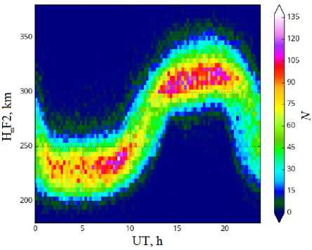
(quarter wavelength for 3 MHz) and 15 m for the upper band (quarter wavelength for 5 MHz). Figure 2 compares BPs for different configurations without phase shift between radiating elements for 3 and 5 MHz in coordinates u= sinθcosφ, v =sinθsinφ, where θ is the angle measured from vertical, φ is the azimuth angle. Table 2 lists the main characteristics of BPs of different configurations in two bands. Along with the standard characteristics there is beam efficiency — a fraction of power radiated in the main lobe of BP [Balanis, 2005] .
2.1. Antenna array with wideband elements
In the configuration of the field with broadband elements, we use dense filling of antennas in the array (rectangular and hexagonal). In the former case, the elements are located at points of intersection of rows and columns of the array. In the second case, triplets of adjacent antennas are at vertices of isosceles triangles, thus forming a regular hexagonal array. Many radars and most heating facilities have been constructed under the scheme with dense filling. Diffraction lobes for the rectangular and hexagonal arrangement of elements are known to appear at the same distance d between antennas [Sharp, 1961] . For the comparison, we therefore use a rectangular array 8×8 (64 elements) and a hexagonal array with edge 5 (61 elements), and set the distance d equal to 40 m in both the cases. This distance between the antennas leads to a diffraction lobe with an elevation angle of ~14.5° at a frequency of 6 MHz, which is, however, considerably suppressed by BPs of the dipoles themselves.
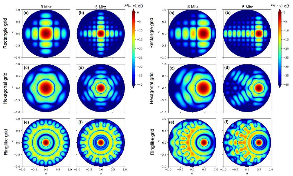
Figure 2 . Comparison between beam patterns of phased arrays of different configurations. Left (without phase shift between radiating elements): a , b — a rectangular array (64 antennas); c , d — a hexagonal array (61 antennas); e , f — a ring array (36 antennas for each subband); a , c , e are for 3 MHz; b , d , f , for 5 MHz. Right — the same for the BP main lobe tilted by 30°
Complete BP for the rectangular array is shown in Figure 2, a , b . We can see that the main side lobes occur along two axes of the array. Since distances between antennas are fixed, the lobe for 5 MHz is narrower than that for 3 MHz. BP for the hexagonal array is depicted in Figure 2, c , d . Like the grid itself, the beam pattern consists of six identical sectors with a step of 60°. Compared to the rectangular array, in BP of the hexagonal array side lobes are located more uniformly and have lower amplitude. Characteristics of different fillings are compared in Table 2. The rectangular array has a high gain and a large average side lobe level. In addition, it occupies a larger space in area of the entire field and required space for one antenna. In the lower frequency band, G is approximately equal for filling of both the types and is 50–100, hence P eff ≈60–90 MW. The power is calculated at 10 kW per antenna, so P eff for the rectangular array will be slightly higher. At the maximum frequency of 6 MHz, G differs and is 500 and 415, and P eff ≈320 MW and 250 MW for the rectangular and hexagonal arrays respectively.
When simulating the array BP with the dense grid, as an antenna we utilized two sets of crossed dipoles with different suspension heights. In the real phased antenna array, such design is unlikely to be suitable — because of the interference of a large number of closely spaced conductors the dipole matching becomes worse. A special broadband antenna is required which retains operating capabilities in the frequency band with a high overlap ratio of 2.4. Nevertheless, the proximity of the conductors and the non-optimal suspension height above ground may result in a situation in which the standing wave ratio of antennas varies in the operating band, therefore P eff decreases. A possible variant may be a log-periodic antenna, but for the given band the antenna design will be complex requiring a large number of high (about 50 m) mast structures, which may decrease the operational efficiency due to considerable operational costs. Moreover, the design and creation of such antennas significantly increase the cost of the heater.
2.2. Dual-band antenna array
In this case, it is expected that the frequency band will be separated into two subbands 2.5–3.5 MHz and 4–6 MHz and the dipole antennas with a simple structure and optimal suspension height in the array with ring structure will be employed. The whole antenna array is a set of dipoles located in four concentric circles of 16 crossed dipoles in each ring, and 4 antennas for each band in the center of the ring (72 antennas). For each subband, the antenna array consists of two rings: for the 2.5–3.5 MHz subband rings have radii of 160 and 320 m; for the 4–6 MHz subband, 100 and 220 m. At the center of the antenna field are 4 crossed dipoles for each subband. Such a structure of antenna arrays with approximately equal gain for each subband allows us to make the most use of the site allocated for them. Moreover, due to separate transmitters for each antenna we can work in a multifrequency mode when
EW is simultaneously transmitted at two frequencies of different subbands. It is possible to halve the number of required transmitters by placing them between the 1–2 and 3–4 rings in radii in which elements of the antenna arrays are located. In this case, only one set of rings works at a time. This structure it is handier to use in the reception mode when IKAR-AI works as an HF locator. Furthermore, the symmetrical structure of the antenna array in azimuth greatly simplifies control of its BP.
Calculated BPs for the ring antenna array at the middle frequency of each subband are shown in Figure 2, e , f ; their characteristics are listed in Table 2. The main lobe of the array is the narrowest of all configurations, but the average level of side lobes in this case is higher than that for the rectangular and hexagonal arrays, specifically for the upper subband. A feature of this array with two rings is a low level of the first side lobes — the main side lobes are closer to the ground. The value of G of the arrays is approximately equal for the subbands (200–250). Thus, the energy potential of the heater with the ring antenna array P eff ≈90÷120 MW in the lower subband and 80÷95 in the upper subband. P eff can increase due to increasing generated HF power, which when using fixed transmitters (10 kW) means an increase in the number of antennas in rings. In the case of ring array, it is, however, more difficult to add additional antennas because the distance between antennas of inner rings is limited. The beam efficiency for the upper boundary of bands of the ring array decreases dramatically because a large part of the power is radiated in the direction of side lobes. This is also evidenced by a decrease in G , although for arrays of other types G is expected to increase with frequency.
Unlike arrays with dense filling, ring antennas are located further apart, therefore the interference between them is lower. Rings of different bands have different radii, and as antennas we can utilize simple crossed dipoles calculated for the corresponding band. In this case, it is easier to maintain the operating capabilities of the antenna in narrow frequency bands with overlap ratios of 1.4 and 1.5 for the lower and upper subbands.
Figure 2 on the right shows BPs at the 30° beam tilt from normal, which corresponds to the coordinates ( u , v )=(0.5, 0). We can see that no diffraction maxima appear for any of the configurations. Nevertheless, the total side lobe level increases, with the greatest increase observed in the ring antenna BP, where the side lobe level exceeds –10 dB in a wide range of directions. This leads to a significant decrease in the antenna gain at the beam steering in the working field of view.
2.3. Results of the preliminary simulation
From the analysis we can draw the following conclusions.
-
1. Arrays with dense filling have the highest G and P eff in the upper frequency subband 4–6 MHz ( P eff ≈160 MW at a frequency of 4 MHz and 320 mW at a frequency of 6 MHz). At low frequencies of the lower subband, the ring array has an advantage in G ( P eff ≈120
-
2. The rectangular array has a greater G than the hexagonal one. The hexagonal array should be considered if it is necessary to save space, for example, if it is planned to deploy two separate antennas with dense filling for different bands.
-
3. Arrays with dense filling require designing a high-quality broadband antenna. On the other hand, ring antennas may be crossed dipoles having an optimum suspension height for different subbands.
-
4. Width of the main lobe of the ring array in the lower band is significantly narrower, and in the upper band it is slightly narrower than in the arrays with dense filling.
-
5. P eff of the ring array can be increased by adding antennas to the rings, but the number of added antennas is limited. On the other hand, the arrays with dense filling are smaller and easier to scale.
-
6. In the ring array, we can employ a multifrequency radiation mode or halve the number of transmitters in use. However, due to separation into two subbands when working in a single frequency mode, we use only half of the antennas and hence half of the transmitters.
-
3. LOCATION OF IKAR-AI
MW at a frequency of 2.5 MHz). The ring array G slightly decreases to the upper boundary of both the subbands due to increasing level of side lobes ( P eff ≈92.5 MW at a frequency of 3.3 MHz — lower than for the rectangular array). The mean P eff in the lower subband for the ring configuration is slightly higher than for the rectangular one. Note that for the ring configuration the operating mode is possible near the intersection of bands when all antennas are working simultaneously. We have calculated this mode at a frequency of 4 MHz and have revealed that P eff can increase up to 180 MW. Moreover, when working in a single-frequency mode in the ring array, only half of the antennas are used. Accordingly, P eff in the lower band is on average the same for the antenna field of all structures.
Thus, if it is possible to create a broadband antenna to operate effectively in the range 2.5–6.0 MHz, a rectangular array is preferable. If we work in a multifrequency mode or cannot develop a broadband antenna with the required characteristics at a suitable cost, it is worthwhile to choose a ring structure. We can also consider an alternative location for two small phased antenna arrays for different subbands at one site. In this case, to save space we can use arrays with the hexagonal grid. Characteristics of such a heating facility in the lower frequency band will be better, hence no need to create a complex broadband antenna.
AND EXISTING
INSTRUMENTAL INFRASTRUCTURE
It is planned to locate IKAR-AI in the former retransmitting center southwest of Odinsk of the Angarsk District of the Irkutsk Region (52.42° N, 103.65° E; geomagnetic inclination θ=17°, the McIlwain parameter L =2.5). To deploy the heating facility including the antenna field and building with control equipment, there is a 700×700 m site near transport and energy networks.
This site has been chosen because the possible region of ionosphere heating should cross the coverage areas of the main instruments of radiophysical and optical monitoring of the upper atmosphere. Moreover, since the heater has a considerable energy potential, it should have the required electric power (~1 MW) and be located outside settlements.
The existing research infrastructure of the Institute of Solar-Terrestrial Physics SB RAS regularly develops and provides the necessary instruments capable of studying AIT properties and its influence on propagation of radio waves of various ranges. The most powerful among the instruments is the Irkutsk Incoherent Scatter Radar (IISR) [Medvedev, Potekhin, 2019] . IS radars diagnose ionospheric plasma, using the method of radio wave scattering by thermal fluctuations of charged-particle density. The analysis is based on the spectrum of Doppler frequency shifts of sounding radio wave, which features plasma and ion-acoustic lines corresponding to scattering by thermal plasma density fluctuations. By analyzing spectral characteristics of a radio signal scattered in plasma, we can gain information about plasma density and temperature, its drift velocity, chemical composition, and other parameters. Monitoring of ionospheric plasma heating by IS radars across the modified region allows us to study physical characteristics of the artificially heated plasma: the spatial structure of temperature and density, the dynamics of these parameters and the typical scales of their changes, spectral characteristics of excited powerful radio-wave high-frequency plasma turbulence.
The new IS-MST radar, developed as part of NHC, will have much more powerful capabilities than the existing radar [Potekhin et al., 2016] . The radar designed according to the scheme of active phased antenna array will operate in a wider range of heights and directions, and also will have a higher spatial resolution both in range and in aspect angle. The estimated relative position of the new and old IS radars and the heating facility and the mutual intersection of the main lobes of their BPs are shown in Figure 3. It becomes possible to study the effects of heating using interferometric methods of recording IS signals for examining the spatial fine structure of the heated region. The successful mutual arrangement of the IS radar and the heating facility enables us to study features of AIT development effects during the ionosphere heating to the magnetic zenith (see Table 1) and to carry out research on artificial generation of magnetic substorms and ionosphere heating-induced energetic electron precipitation from Earth's radiation belt into the upper atmosphere.
One of the main tools for diagnosing vertical profiles of parameters and components of the neutral atmosphere is considered to be lidars. Intensity and spectral characteristics of the monochromatic laser radiation scattered in the upper atmosphere allow us to obtain vertical profiles of density, chemical composition (particularly metal Na, K layers) of aerosol, and air temperatures. For this purpose, we plan to use the MS lidar developed as part of NHC, which is capable of diagnosing the neutral component of the upper atmosphere in the region modified by IKAR-AI.
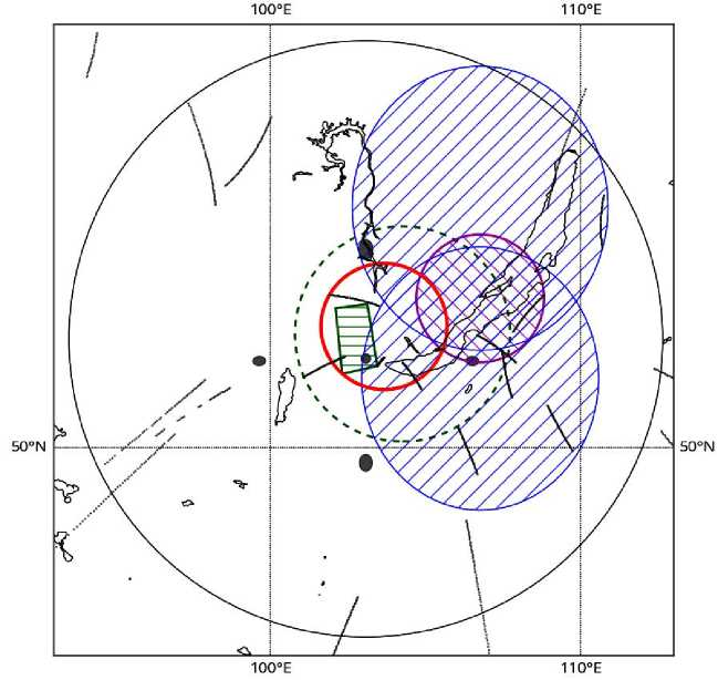
Figure 3 . Arrangement of NHC instruments. Projections of fields of view of the instruments at an altitude of 250 km on Earth's surface. The thick red circle indicates the heating facility IKAR-AI; blue ellipses with right hatching show the IS-MST radar; the purple circle with left hatching is the MS lidar; the green trapezium with horizontal hatching is the existing IS radar; the green dashed circle is the existing ionosonde DPS-4; the black circle is an all-sky camera; gray ellipses mark a Fabry—Perot interferometer, gray curves are subionospheric points of GNSS satellite—receiver lines
The profiles of parameters of the neutral component of the upper atmosphere, derived in the total volume with the profiles of charged component parameters (see Figure 3), will allow us to determine height features of energy exchange between the charged and neutral components.
Of particular importance for the study of features of the small-scale part of artificial ionospheric irregularities is their diagnostics by the method of aspect scattering of MF and HF radio waves. Due to the relative proximity of Russia's southern border to IKAR-AI (about 250 km), we cannot study radiowave backscattering in the band above 10–15 MHz. Aspect scattering is, however, possible in the band 1–10 MHz for signals from the stations adjacent (to 200–400 km) to the heater. For this purpose, we can use signals from ionosondes. We can also receive scattered signals from stations in the band 10–15 MHz if they are to the east and west of the heater, with the receiver located as far to the south of the heater as possible. In this case, receiving conditions will largely depend on the refraction of radio waves in the ionosphere.
The HF radio sounding infrastructure that is currently available near IKAR-AI and is supported by ISTP SB RAS includes a digital vertical sounding (VS) ionosonde DPS-4 (Irkutsk) [Haines, Reinisch, 1995] and a multifunctional chirp ionosonde Ionosonde-MS [Podlesnyi et al., 2013] at the village of Tory, which performs vertical and near-vertical sounding over the Usolye–Tory path (the radio path length is ~120 km).
In the future, additional near-vertical radio paths can be deployed. These instruments can record the dynamics (including rapid processes) of ionospheric disturbances of various scales, which occur below the ionospheric peak height directly in the heating area. Small- and mediumscale disturbances can be identified at the most basic level by analyzing temporal variations of the main ionospheric parameters (critical frequencies and virtual heights of ionospheric layers), or by using the so-called amplitude maps (A-maps) [Akchurin et al., 2013; Kurkin et al., 2014] , or from a change in height frequency characteristics (HFC) on VS ionograms [Laryunin, Kurkin, 2011; Laryunin et al., 2014] .
More advanced methods can restore the smoothed full vertical electron density profile from estimated HFC [Mikhailov, 2000; Reinisch, Huang, 1983] , thus identifying medium and large-scale disturbances. The analysis of VS ionograms also enables us to record such phenomena as F-spread and occurrence of sporadic structures in the heating area.
The network of oblique chirp sounding, supported by ISTP SB RAS, with transmitting sites in Magadan, Norilsk, Khabarovsk, and a receiving site in the village of Tory will allow us to detect wave-like ionospheric disturbances (internal gravity waves [Andreeva et al., 2016]) excited during periodic heating of ionospheric plasma by powerful radio waves. The coherent IS radar planned to be located near Irkutsk will enable us to diagnose and monitor medium- and large-scale ionospheric disturbances propagating from the heating area, using the oblique backscatter technique at a fixed frequency [Oinats et al. 2013; Oinats et al., 2016].
When studying characteristics of artificial plasma perturbations, signals from global navigation satellite systems (GNSS) GPS, GLONASS, Galileo, Bei-Dou/Compass et al. are planned to be used. The GNSS technology [Afraimovich, Perevalova, 2006] has been actively employed in recent years, in particular to study the effects of ionospheric modification by powerful HF radiation [Frolov, 2017; Kunitsyn et al., 2011, 2012] . A key measured parameter in the GNSS sounding is the total electron content (TEC) determined from dual-frequency measurements. Its variations are quite sensitive to ionospheric disturbances of various types. The technique for determining TEC developed for GNSS receivers and the possibility of detecting phase and amplitude scintillations of a navigation radio signal by the network of receivers located near the heating facility allow us to study characteristics of electron density irregularities of different scales, generated in the coverage area of the heater.
The relatively low price of the recording equipment allows for the development of sufficiently dense networks of stations. Currently, the ISTP SB RAS network SibNet consisting of eight receiving sites is deployed in the near-Baikal Region [Yasyukevich et al., 2018] . It records GPS/GLONASS/Galileo signals, as well as BeiDou/Compass signals at one of the stations. The coverage density of sud-ionospheric points (points of intersection of the satellite–receiver line and the thin spherical layer at a height of 300 km) is shown in Figure 3. To construct it, we have used 0.5 hr measurements. The data reported allows us to detect ionospheric disturbances near the heater. Improving the spatial resolution requires the deployment of additional sites. Geostationary TEC observations based on the reception of SBAS signals [Kunitsyn et al., 2015] are inefficient in this case as their sub-ionospheric points are far to the south of the heater. Moreover, elevation angles to satellites are 12°–30°, and the location of stations to the north of the sites in use will further reduce the elevation angle.
In addition to the vertical/oblique sounding of the ionosphere, detection of artificial ionospheric radiation, and other radiophysical methods for diagnosing the ionospheric region disturbed by HF radiation, the artificial optical glow of the ionosphere is recorded and its characteristics are analyzed [Biondi et al,. 1970; Bernhardt et al., 2000]. One of the main methods for recording spatial distributions is the use of special wide-angle cameras (all-sky cameras) based on low-noise high-sensitive CCD matrices with narrowband interference filters transmitting primary vertically stratified optical emissions of the upper atmosphere. The 630 nm atomic oxygen emission is associated with the suprathermal electrons (>2 eV) accelerated by plasma waves. As theoretically predicted [Vas’kov et al., 1983; Gurevich et al., 1985], the maximum airglow brightness should be shifted toward a more dense at- mosphere downward from the region of acceleration in the turbulent layer over a distance of a few mean free paths of electrons with energy >2 eV. This has been observed experimentally in [Haslett, Megill, 1974; Gustavsson et al., 2001, 2008]. Measurements of the vertical profile of the artificial airglow brightness are of interest as a method for studying energy characteristics of suprathermal electrons and experimental verification of theoretical models of acceleration and penetration of accelerated electrons up and down from the turbulent layer. The experimental data published to date [Haslett, Megill, 1974; Gustavsson et al., 2001, 2008; Pedersen et al., 2011a] is insufficient to construct a physical model of acceleration and propagation of electrons from the plasma turbulence region [Shindin et al., 2018]. The use of stereoscopic systems based on all-sky cameras is therefore much sought after in studies of ionosphere modification.
The optical airglow has a line spectrum. The ratio of spectral radiation components provides information on dynamics of photochemical reactions and gas temperature; and characteristics of the lines — their position and width — reflect the speed and temperature of the luminous substance. Therefore, the use of modern diffraction spectrometers with cooled highly sensitive photosensors as NHC optical instruments will help to determine the degree of change in the course of chemical reactions in the upper atmosphere depending on the degree and nature of the ionosphere modification, as well as on the electron temperature. The ratio of intensities of the artificially generated red and green atomic oxygen lines will define the height at which the energy release is maximum, and also will indicate the occurrence of induced particle precipitation. The use of modern Fabry—Perot interferometers adapted for aerodynamic research [Shiokawa et al., 2012] will help to assess the degree of heating of the neutral component of the upper atmosphere and the local change in circulation (wind) due to energy transfer from the modified charged component of the upper atmosphere to the neutral one.
CONCLUSION
The heating facility IKAR-AI takes into account the extensive experience in heating in Russia and abroad, as well as requirements arising from currently unresolved problems.
The proposed frequency band, as shown by the results of previous studies, is the best to undertake new research at IKAR-AI. The transfer of shortwave radiation energy to a charged component of the upper atmosphere is the most effective in the lower band 2.5–3.5 MHz, where the second electron gyrofrequency harmonic is located and the most intense generation of AIT including optical airglow occurs. The upper part of the 4–6 MHz band enables the efficient operation of the heating facility at a higher level of solar activity, as well as the use of IKAR-AI as a short-wave radar for ionospheric diagnostics.
Simulation of different configurations of the antenna field has shown that it is possible to create the heating facility with required energy characteristics, with the rectangular array having a higher effective power in the upper part of the frequency band than the ring array. The development of the array with dense filling is, however, hampered by the necessity of designing a broadband antenna for efficient operation in the 2.5–6.0 MHz band. In the future, we should consider an alternative location for two hexagonal arrays for lower and upper subbands.
The full use of the heater as an HF radar involves using a radar frequency band below 10 MHz and above, but the fulfillment of this requirement may considerably complicate the design of antennas and reduce its efficient operation in the 2.5–6.0 MHz band. It is therefore not necessary to expand the frequency band to 10 MHz to create a fully-featured high-potential radar. Perhaps, in real conditions we have to increase the upper limit of the band by ~1 MHz, which will cause only a slight deterioration of the IKAR-AI antenna characteristics. IKAR-AI will be capable of working as a radar exploring the ionosphere by the method of partial reflections in the lower part of the operating band (2.5 MHz) or as a short-wave radar in the upper part of the band (6 MHz and higher) after its deployment. For this purpose, each radiating element will need to be equipped with appropriate digital receivers. Recorded radar signals can be transmitted through fiber optic lines of the transmitter control system, and the device summing up the signals from antennas can be installed in the IKAR-AI control center.
The heater IKAR-AI as part of NHC is an instrument facilitating active experiments on the influence on active processes in Earth's upper atmosphere. It provides a means for full-scale simulation of the processes influencing space weather and the artificial generation of certain events: induced particle precipitation, generation of internal gravity waves in the upper atmosphere, excitation of magnetospheric resonances, etc. The charged component of the upper atmosphere (preferably heated electrons) modified by the powerful radiation of the heater will transfer the resulting energy to ions and neutral component of the upper atmosphere. Features of the process and its effectiveness are the key points for the problems of space weather, in which it is necessary to investigate energy transport from the charged component to the neutral one. For the first time in history of radiophysical research into the upper atmosphere in Russia, the operational commissioning of IKAR-AI as part of NHC will provide us with the most complete set of modern observational instruments for studying the energy transport between atmospheric components. Such instruments are the IS-MST radar and MS lidar, as well as a wide range of existing and developed optical and radiophysical facilities for monitoring the upper atmosphere. The facilities placed in one region will enable us to monitor vertical profiles of parameters of the ionosphere, modified by powerful HF radio waves, and the neutral component of the upper atmosphere, to estimate the intensity and spatial structure of plasma irregularities, to record variations in the course of chemical reactions, in particular for small atmospheric components, to study the dynamics of charged particles. Thus,
IKAR-AI and various instruments deployed around it will help to determine more precisely cross-sections of the interaction between ions, electrons and neutral atoms of nitrogen, oxygen, and other atmospheric components at relatively low collision energies, which is difficult to accomplish with ground-based plasma facilities and particle accelerators.
The results will allow researchers to take a new look at the role of various physical-chemical processes in the upper atmosphere and to make a qualitative shift in the understanding of solar-terrestrial relations, formation of space weather, atmosphere and near-Earth space physics.
The work was carried out with the financial support of RAS Presidium Program No. 56 “Fundamentals of innovative technologies in national security interests”. Frolov V.L. has carried out his work under the grant from the Ministry of Science and Higher Education of the Russian Federation received under FTP “Investigations and developments in priority areas of development of the science and technology sector of the Russian Federation for 2014–2020” (Project ID RFMEFI62020X0003, agreement number 075-15-2020-529).
Список литературы Современный нагревный стенд для исследования ионосферы средних широт
- Акчурин А.Д., Юсупов К.М., Шерстюков О.Н., Ильдиряков В.Р. Выделение быстротекущих и мелкомасштабных неоднородностей на одноминутных ионограммах ионозонда "Циклон" // Гелиогеофизические исследования. 2013. № 4. С. 101-110.
- Афраймович Э.Л., Перевалова Н.П. GPS-мониторинг верхней атмосферы Земли. Иркутск: ГУ НЦ РВЧ ВСНЦ СО РАМН, 2006. 480 с.
- Беликович В.В., Бенедиктов Е.А., Толмачева А.В., Бахметьева Н.В. Исследование ионосферы с помощью искусственных периодических неоднородностей. Н. Новгород: ИПФ РАН, 1999. 156 с.
- Беляев П.П., Котик Д.С., Митяков С.H. и др. Генерация сигналов комбинационных частот в ионосфере // Изв. вузов. Радиофизика. 1987. Т. 30, № 2. С. 248-286.
- Гинзбург В.Л. Распространение электромагнитных волн в плазме. М.: Наука, 1967. 683 c.
- Грач С.М. О кинетических эффектах в F-области ионосферы, возмущенной мощными радиоволнами // Изв. вузов. Радиофизика. 1999. Т. 42, № 7. С. 651-669.
- Грач С.М., Сергеев Е.Н., Шиндин А.В. и др. Искусственные ионосферные слои при частотах волны накачки в области 4-й электронной гирогармоники на стенде HAARP // Доклады Академии наук. 2014. Т. 454, № 5. С. 526-530.
- Грач С.М., Сергеев Е.Н., Мишин Е.В. и др. Динамические характеристики плазменной турбулентности ионосферы, инициированной воздействием мощного коротковолнового радиоизлучения // УФН. 2016. T. 186, № 11. С. 1189-1228.
- DOI: 10.3367/UFNr.2016.07.037868
- Гуревич А.В. Нелинейные явления в ионосфере // УФН. 2007. Т. 177, № 11. С. 1145-1177. 10.3367/UFNr.0177. 200711a.1145.
- DOI: 10.3367/UFNr.0177.200711a.1145
- Ерухимов Л.М., Генкин Л.Г. Ионосфера как космическая плазменная лаборатория (обзор) // Изв. вузов. Радиофизика. 1992. Т. 35, № 11-12. С. 863-888.
- Изв. вузов. Радиофизика. 1999. Т. 42, № 7-8. С. 599-826. (Спец. вып.).
- Изв. вузов. Радиофизика. 2005. Т. 48, № 9. С. 719-822. (Спец. вып.).
- Изв. вузов. Радиофизика. 2008. Т. 51, № 11. С. 915-1003. (Спец. вып.).
- Изв. вузов. Радиофизика. 2012. Т. 55, № 1-2. С. 1-140. (Спец. вып.).
- Куркин В.И., Ларюнин О.А., Подлесный А.В. Анализ квазиволновых возмущений ионосферы с помощью амплитудных карт по данным ЛЧМ-ионозонда ИСЗФ СО РАН // XXIV Всероссийская научная конференция "Распространение радиоволн (РРВ-24)": Труды конференции. Иркутск, 2014. С. 214-215.
- Ларюнин О.А., Куркин В.И. Восстановление параметров ионосферных возмущений по динамике серпообразных особенностей на ионограммах // Солнечно-земная физика. 2011. Вып. 19. С. 107-115.
- Ларюнин О.А., Куркин В.И., Подлесный А.В. Использование данных двух близко расположенных ионозондов при диагностике перемещающихся ионосферных возмущений // Электромагнитные волны и электронные системы. 2014. Т. 19, № 1. С. 10-17.
- Михайлов С.Я. Многозначность восстановления профилей плазменной частоты по заданной ВЧХ и их различимость для наклонного распространения коротких радиоволн в изотропной ионосфере // Изв. вузов. Радиофизика. 2000. Т. XLII, № 10. С. 855-872.
- Ойнац А.В., Куркин В.И., Нишитани Н., Сайто А. Определение параметров перемещающихся ионосферных возмущений по данным радаров SuperDARN // Электромагнитные волны и электронные системы. 2013. Т. 18, № 8. С. 30-39.
- Подлесный А.В., Брынько И.Г., Куркин В.И. и др. Многофункциональный ЛЧМ-ионозонд для мониторинга ионосферы // Гелиогеофизические исследования. 2013. № 4. С. 24-31.
- Потехин А.П., Сетов А.Г., Лебедев В.П. и др. Перспективный радар НР-МСТ: потенциал и диагности-ческие возможности // Солнечно-земная физика. 2016. Т. 2, № 3. С. 3-16.
- DOI: 10.12737/19444
- Фролов В.Л. Искусственная турбулентность среднеширотной ионосферы. Н. Новгород: Изд-во Национального исследовательского Нижегородского государственного университета им. Н.И. Лобачевского, 2017. 468 c.
- Фролов В.Л., Рапопорт В.О., Шорохова Е.А. и др. Характеристики электромагнитных и плазменных возмущений, индуцируемых на высотах внешней ионосферы Земли при модификации F2-области мощным КВ-радиоизлучением стенда СУРА // Изв. вузов. Радиофизика. 2016. Т. 59, № 3. С. 198-222.
- Фролов В.Л., Акчурин А.Д., Болотин И.А. и др. Высыпания энергичных электронов из радиационного пояса Земли, стимулированные модификацией среднеширотной ионосферы мощными КВ-радиоволнами // Изв. вузов. Радиофизика. 2019. Т. 62, № 9.
- Черногор Л.Ф., Гармаш К.П., Фролов В.Л. Крупномасштабные возмущения в нижней и средней ионосфере, сопровождавшие воздействие на ионосферу радиоизлучением стенда СУРА // Изв. вузов. Радиофизика. 2019. Т. 62, № 6. С. 440-459.
- Шлюгер И.С. Самомодуляция мощного электромагнитного импульса, отраженного от верхних слоев ионосферы // Письма в ЖЭТФ. 1974. Т. 19, вып. 5. С. 247-251.
- Ясюкевич Ю.В., Веснин А.М., Перевалова Н.П. Сибирская сеть приемников сигналов глобальных навигационных спутниковых систем SibNet: текущее состояние // Солнечно-земная физика. 2018. Т. 4, № 4. С. 82-94.
- DOI: 10.12737/szf-44201809
- Andreeva E.S., Frolov V.L., Kunitsyn V.E., et al. Radiotomography and HF ray tracing of the artificially disturbed ionosphere above the Sura heating facility // Radio Sci. 2016. V. 51, iss. 6. P. 638-644.
- DOI: 10.1002/2015RS005939
- Balanis C.A. Antenna Theory. Analysis and Design. 3rd Edition. John Wiley & Sons, Inc. Publ., 2005. 1099 p.
- Bernhardt P.A., Wong М, Huba J.D., et al. Optical remote sensing of the thermoshere with HF pumped artificial airglow // J. Geophys. Res. 2000. V. 105, N A5. P. 10657-10671.
- Biondi A.A., Sipler D.P., Hake R.D. Jr. Optical (λ=6300) detection of radio frequency heating of electrons in the F-region // J. Geophys. Res. 1970. V. 75, N 31. P. 6421.
- Erukhimov L.M., Metelev S.A., Myasnikov E.N., et al. Artificial ionospheric turbulence (a review) // Radiophys. Quantum Electronics. 1987. V. 30, N 2. P. 208-225.
- Grach S.M., Men'kova Yu.E., Stubbe P. On the penetration of upper hybrid waves into a plasma depletion // Adv. Space Res. 2004. V. 34, iss. 11. P. 2428-2432.
- Gurevich A.V. Nonlinear phenomena in the ionosphere. New York: Springer Publ., 1978. 372 p.
- Gurevich A.V., Dimant Ya.S., Milikh G.M., Vaskov V.V. Multiple acceleration of electrons in the regions of high-power radio-wave reflection in the ionosphere // J. Atmos. Terr. Phys. 1985. V. 47, N 11. P. 1057-1070.
- Gustavsson B., Sergienko T., Rietveld M.T., et al. First tomographic estimate of volume distribution of HF-pump enhanced airglow emission // J. Geophys. Res.: Space Phys. 2001. V. 106, N A12. P. 29105-29124.
- Gustavsson B., Kosch M., Wong A., et al. First estimates of volume distribution of HF-pump enhancedemissions at 6300 and 5577 Å: a comparison between observationsand theory // Ann. Geophys. 2008. V. 26, N 12. P. 3999-4012.
- Haines D.M., Reinisch B.W. Digisonde Portable Sounder System Manual // University of Massachusetts Lowell Center for Atmospheric Research. 1995. 45 p.
- Haslett J.C., Megill L.R. A model of the enhanced airglow excited by RF radiation // Radio Sci. 1974. V. 9, N 11. P. 1005.
- J. Atmos. Terr. Phys. 1982. V. 44, N 12. P. 1005-1171. (Special Iss.).
- J. Atmos. Terr. Phys. 1985. V. 47, N 12. P. 1149-1333. (Special Iss.).
- J. Atmos. Terr. Phys. 1997. V. 59, N 18. P. 2251-2488. (Special Iss.).
- J. Geophys. Res. 1970. V. 75, N 31. P. 5961-6452. (Special Iss.).
- Kosch M.J., Rietveld M. T., Kavanagh A. J., et al. High-latitude pump-induced optical emissions for frequencies close to the third electron gyro-harmonic // Geophys. Res. Lett. 2002. V. 29, iss. 23. CiteID 2112.
- DOI: 10.1029/2002GL015744
- Kosch M.J., Pedersen T., Mishin E., et al. Coordinated optical and radar observations of ionospheric pumping for a frequency pass through the second electron gyroharmonic at HAARP // J. Geophys. Res. 2007. V. 112, A12317. 10.1029/ 2006JA015854.
- DOI: 10.1029/2006JA015854
- Kunitsyn V.E., Padokhin A.M., Vasiliev A.E., et al. Study of GNSS-measured ionospheric total electron content variations generated by powerful HF-heating // Adv. Space Res. 2011. V. 47, N 10. P. 1743-1749.
- DOI: 10.1016/j.asr.2010.03.031
- Kunitsyn V.E., Andreeva E.S., Frolov V.L., et al. Sounding of HF heating-induced artificial ionospheric disturbances by navigational satellite radio transmissions // Radio Sci. 2012. V. 47, RS0L15.
- DOI: 10.1029/2011RS004957
- Kunitsyn V., Kurbatov G., Yasyukevich Yu., Padokhin A. Investigation of SBAS L1/L5 signals and their application to the ionospheric TEC studies // Geoscience and Remote Sensing Lett. 2015. V. 12, N 3. P. 547-551. 10.1109/LGRS. 2014.2350037.
- DOI: 10.1109/LGRS.2014.2350037
- Leyser T.B. Stimulated electromagnetic emissions by high-frequency electromagnetic pumping of the ionospheric plasma // Space Sci. Rev. 2001. V. 98, N 3-4. P. 223-328. :1013875603938.
- DOI: 10.1023/A
- Lukianova R., Frolov V., Ryabov A. First SWARM observations of the artificial ionospheric plasma disturbances and field-aligned currents induced by the SURA power HF heating // Geophys. Res. Lett. 2019. (accepted for publication, Paper #2019GL085833R).
- DOI: 10.1029/2019GL085833
- Medvedev A.V., Potekhin A.P. Irkutsk Incoherent Scatter Radar: history, present and future // History of Geo- and Space Sci. 2019. V. 10, iss. 2. P. 215-224.
- DOI: 10.5194/hgss-10-215-2019
- Mishin E., Sutton E., Milikh G., et al. F2-region atmospheric gravity waves due to high-power HF heating and subauroral polarization streams // Geophys. Res. Lett. 2012. V. 39, L11101.
- DOI: 10.1029/2012GL052004
- Mishin E., Wotkins B., Lehtinen N., et al. Artificial ionospheric layers driven by high-frequency radio waves: An assessment // J. Geophys. Res.: Space Phys. 2016. V. 121, iss. 4. Р. 3497-3524.
- DOI: 10.1002/2015JA021823
- Oinats A.V., Nishitani N., Ponomarenko P., Ratovsky K.G. Diurnal and seasonal behavior of the Hokkaido East SuperDARN ground backscatter: simulation and observation // Earth, Planets and Space. 2016. V. 68. Article id. 18.
- DOI: 10.1186/s40623-015-0378-9
- Pedersen T., Gustavsson B., Mishin E., et al. Optical ring formation and ionization production in high-power HF heating experiments at HAARP // Geophys. Res. Lett. 2009. V. 36, iss. 18, L18107.
- DOI: 10.1029/2009GL040047
- Pedersen T.R., Holmes J.M., Gustavsson B., Mills T.J. Optical imaging of artificial ionospheric plasmas // IEEE Trans. Plasma Sci. 2011а. V. 39, N 11. P. 2704-2705.
- Pedersen T., McCarrick M., Reinisch B., Watkins B., Hamel R., Paznukhov V. Production of artificial ionospheric layers by frequency sweeping near the 2nd gyroharmonic // Ann. Geophys. 2011b. V. 29. P. 47-51.
- DOI: 10.5194/angeo-29-47-2011
- Perkins F.W., Oberman C., Valeo E.J. Parametric instabilities and ionospheric modification // J. Geophys. Res. 1974. V. 79, N A10. P. 1478-1496.
- Reinisch B.W., Huang X. Automatic calculation of electron density profiles from digital ionograms: 3. Processing of bottom side ionograms // Radio Sci. 1983. V. 18, N 3. P. 477-492.
- Sergeev E., Grach S., Shindin A., et al. Artificial ionospheric layers during pump frequency stepping near the 4th gyroharmonic at HAARP // Phys. Rev. Lett. 2013. V. 110, iss. 6-8, 065002.
- DOI: 10.1103/PhysRevLett.110.065002
- Sharp E. A triangular arrangement of planar-array elements that reduces the number needed // IRE Transactions on Antennas and Propagation. 1961. V. 9, N 2. P. 126-129.
- DOI: 10.1109/TAP.1961.1144967
- Shindin A.V., Klimenko V.V., Kogogin D.A., et al. Spatial characteristics of the 630-nm artificial ionospheric airglow generation region during the Sura facility pumping // Radiophysics and Quantum Electronics. 2018. V. 60, N 11. P. 849-865.
- DOI: 10.1007/s11141-018-9852-0
- Shiokawa K., Otsuka Y., Oyama S., et al. Development of low-cost sky-scanning Fabry-Perot interferometers for airglow and auroral studies // Earth, Planets and Space. 2012. V. 64, iss. 11. P. 1033-1046.
- DOI: 10.5047/eps.2012.05.004
- Streltsov A.V., Berthelier J.J., Chernyshov A.A., et al. Past, present and future of active radio frequency experiments in space // Space Sci. Rev. 2018. V. 214, N 118. 10.1007/ s11214-018-0549-7.
- DOI: 10.1007/s11214-018-0549-7
- Stubbe P. Review of ionospheric modification experiments at Tromsø // J. Atmos. Terr. Phys. 1996. V. 58, N 1-4. P. 349-368.
- DOI: 10.1016/0021-9169(95)00041-0
- Stubbe P., Hagfors T. The Earth's ionosphere: A wall-less plasma laboratory // Surveys in Geophysics. 1997. V. 18, N 1. P. 57-127. :10065831.
- DOI: 10.1023/A
- Stubbe P., Kopka H., Dowden R.L. Generation of ELF and VLF waves by polar electrojet modulation: Experimental results // J. Geophys. Res. 1981. V. 86, N A11. P. 9073-9078.
- Vartanyan A., Milikh G.M., Mishin E., et al. Artificial ducts caused by HF heating of the ionosphere by HAARP // J. Geophys. Res. 2012. V. 117, A10307. 10.1029/ 2012JA017563.
- DOI: 10.1029/2012JA017563
- Vas'kov V.V., Gurevich A.V., Dimant Ya.S. MUltiple acceleration of electrons in plasma resonance // Journal of Experimental and Theoretical Physics. 1983. V. 57, N 2. P. 310.
