Spacecraft motion in a low circular orbit in establishing intersatellite link

Author: Kolovsky I. K., Shmakov D. N.
Journal: Siberian Aerospace Journal @vestnik-sibsau-en
Section: Aviation and spacecraft engineering
Article in issue: 4 vol.20, 2019.
Free access
The article investigates the problem of inter-satellite linking in the constellation of spacecraft in a low circular orbit. A specific problem of establishing intersatellite link (IL) in that orbit – cross-pointing of the antennae – is also studied. To support cross-tracking, it is important to place spacecraft (SC) in the orbital plane so that they are constantly in the zone of mutual visibility. The line-of-sight range is analyzed both in one orbital plane and between adjacent planes. IL is treated in terms of the orbital constellation (OC) ballistic formation. Several typical modes of motion of SC with IL in adjacent planes are determined – parallel, orthogonal, oncoming. The parameter values of IL antenna pointing are also assessed. The obtained results of OC formation and antenna pointing parameters’ calculations may be relevant for establishing a modified system.
Ballistics, range, low circular orbit, orbital constellation, intersatellite link.
Short address: https://sciup.org/148321708
IDR: 148321708 | UDC: 629.7.016.3 | DOI: 10.31772/2587-6066-2019-20-4-465-476
Text of the scientific article Spacecraft motion in a low circular orbit in establishing intersatellite link
Introduction. Intersatellite links can increase the efficiency in achieving the principle objective of satellite systems – providing communications for subscribers distributed globally. Besides, operating IL helps to solve the problems of parallel control of all spacecraft in the constellation without numerous ground tracking stations [1].
There are several satellite systems which provide monitoring and data transmission, such as “Globalstar”, “Iridium”. Development of such intersatellite systems is also essential for solving various problems of data transmission, monitoring and locating moving objects. Technical solutions of these systems provide the basis of monitoring facilities development [2; 3].
The aim of IL is to provide radio exchange of subscribers not in the line of sight of the same spacecraft -that requires information exchange both between SC in the same plane and between ones in different planes. The use of IL significantly increases the efficiency of radio links [4]:
-
– the service area is increased by interconnection of all radio visibility zones (RVZ) of SC into an integrated RVZ of the orbital constellation;
-
– the load on the satellite links is reduced due to instant information exchange;
-
– the reliability and stability of satellite links is increased.
Establishing IL in OC of SC. For the experiment we assume that there is an OC of 24 SC in a near-circular orbit of 1500 km altitude, and from the point of view of the OC ballistic formation and SC motion, we review the ways of plotting the IL for the given satellite system, both in one plane and between adjacent planes. A similar IL configuration is already introduced in “Iridium” satellite system [5]. “Iridium” is a low-orbit system operating in circular orbits. The orbit altitude is about 700 km; the standard OC includes 66 interlinked SC [6].
When an IL are made in a circular orbit of 1500 km altitude, the optimal mutual visibility of SC in the orbital plane is achieved when the number of SC in the plane is more than or equals 6 [7].
It must be noted that for IL correct operation in one plane, orbit correction must be carried out to keep the orbital position of all SC stable, otherwise the distance between the SC can alter too much and cause operational failure.
We can determine the station-keeping zone and positioning of SC in the orbital plane for IL operation in reference to 5, 6, 7 SC. It is necessary to view the orbit configuration of SC 1 and SC 2 in more detail (fig. 1).
The symbols in fig.1 are: a – Earth radius; b – halfdistance between SC 1 and SC 2; с – major semi-axis of SC orbit; ∠β – half of the center angle between SC 1 and SC 2.
We take the basic relation of a right-angled triangle [8] to calculate 2∙∠β – the limit angle of keeping SC in the line of sight a = 6378.16 km – Earth radius [9];
с = 1500 + 6378.16 = 7878,16 km – major semi-axis of SC orbit;
sin α = a / c ;
∠α = 54.056°;
∠β = 35.944°;
2∙ ∠β = 71.888°. (1)
According to the formula (1), for a number of SC composition variants in the orbital plane, we obtain the
values of the angle between the nearest SC and of the station-keeping zone (tab. 1).
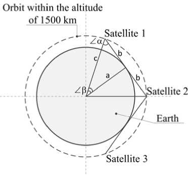
Fig. 1. IL within an orbital plane
Рис. 1. МЛС внутри орбитальной плоскости
The results in tab. 1 show that for IL at 1500 km altitude with five SC in the plane, to provide mutual visibility it is necessary to keep the SC in orbit with an accuracy of 0.5° by latitude argument, which is quite demanding technically.
Therefore, an architecture of 6 SC in the plane with ± 5° station-keeping zone relative to the SC orbital position can be applicable. In this case, the distance between two adjacent SC with an IL will depend on the accuracy of keeping the SC in the orbital positions with respect to the latitude argument. Half-distance value between adjacent SC with IL (parameter b in fig. 1) when there are 6 SC in the orbital plane will make b = с∙sinβ. (2)
In case 6 SC are evenly positioned in the plane, (the center angle between these SC is 60 °) and the stationkeeping accuracy is ± 5º, the expression (2) gives the 7878 km distance in the nominal position. The distance calculations for the center angle of 50° and 70° are listed in tab. 2.
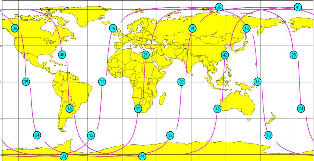
We form the chosen for the experiment standard OC architecture of 24 SC for modeling and studying the ballistic parameters of IL as follows: four orbital planes of 6 SC each (tab. 3).
Absolute longitude divergence of the ascending nodes of adjacent orbital planes is 46°. The SC phase distribution is taken for the moment of SC 11 passing the ascending node of the orbit.
Fig. 2 represents 24 SC in four orbital planes and the track of every SC in flight period of a few minutes.
Table 1
Station-keeping zone for a SC with 1.500 km orbit altitude operating IL
|
SC number in the orbital plane |
SC positioning in the plane with respect to the argument of latitude, ° |
Station-keeping zone, ° |
|
5 |
71.9 |
±0.5 |
|
6 |
60.0 |
±5.0 |
|
7 |
51.4 |
±9.3 |
Table 2
|
Distance between SC, 2∙ b , km |
Center angle between SC, 2∙ ∠β , ° |
|
|
Minimal |
6658 |
50 |
|
Nominal |
7878 |
60 |
|
Maximal |
9037 |
70 |
Table 3
Distribution for OC of 24 SC
|
Plane number |
SC number |
Ascending node longitude, ° |
Argument of latitude, ° |
Plane number |
SC number |
Ascending node longitude, ° |
Argument of latitude, ° |
|
1 |
11 |
0 |
0 |
3 |
31 |
92 |
50 |
|
12 |
0 |
60 |
32 |
92 |
110 |
||
|
13 |
0 |
120 |
33 |
92 |
170 |
||
|
14 |
0 |
180 |
34 |
92 |
230 |
||
|
15 |
0 |
240 |
35 |
92 |
290 |
||
|
16 |
0 |
300 |
36 |
92 |
350 |
||
|
2 |
21 |
46 |
25 |
4 |
41 |
138 |
75 |
|
22 |
46 |
85 |
42 |
138 |
135 |
||
|
23 |
46 |
145 |
43 |
138 |
195 |
||
|
24 |
46 |
205 |
44 |
138 |
255 |
||
|
25 |
46 |
265 |
45 |
138 |
315 |
||
|
26 |
46 |
325 |
46 |
138 |
15 |
Fig. 2. Routes of 24 SC in the OC
Рис. 2. Трассы ОГ из 24-х КА
Values of distance and center angle between SC in the plane
ма md so е « ■ uo «о мо
IL is a unique element of “Iridium” communication system, every SC of which is interconnected with 4 adjacent ones, 2 of them in front and in aft position in the same orbital plane, and 2 on the left and on the right in adjacent orbital planes [10].
For the experimental OC architecture of 24 SC we can outline the following IL configurations:
-
– Configuration 1 – IL between the SC in one orbital plane;
-
– Configuration 2 – IL between SC of adjacent planes № 1 and 2, № 2 and 3, № 3 and 4 (parallel motion);
-
- Configuration 3 - IL between SC in planes № 1 and
-
3, № 2 and 4 (orthogonal motion in the moment of mutual visibility);
-
- Configuration 4 - IL between SC in planes № 1 and 4 (cross-movement in the moment of mutual visibility).
Operating IL dictates the need of continuous communication during the SC flight. The analysis of this aspect is presented in [11] for “CubeSat” system.
Below, there is an analysis of some specified SC from every orbital plane in the experimental OC of 24 SC, as well as of ballistic parameters variation for each of the IL configurations, including the periods of SC mutual visibility.
Here is an analysis of the following ballistic parameters:
-
– the SC positioning range and the rate of its changing;
-
– declination and the rate of its changing;
-
– elevation and the rate of its changing;
-
– period of mutual visibility in an orbit pass.
These parameters allow to determine SC antenna control characteristics in IL communication, as well as the mutual visibility periods of SC within IL zone.
Configuration 1 – IL between the SC in one orbital plane . Fig. 3 presents an IL variant in one plane, when all RVZ of six SC (at an elevation angle of 10 °) are networked into a common RVZ of the orbital plane. Common RVZ will significantly increase the coverage zone.
Further we review the requirements for IL-providing equipment on the example of two most closely positioned sC of the first orbital plane SC № 11 and SC № 12. Fig. 4 presents the SC, their subsatellite points and flight route.
Tab. 4 presents the initial data - SC №11 and SC № 12 reference. MDT - Moscow decree time in the ascending node, the SC coordinates and velocities are in the Greenwich rotating coordinate system (GRCS).
Let us review the information transfer for SC № 11 to SC № 12 in the nominal position during one orbit pass (115 min).
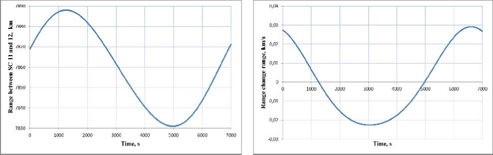
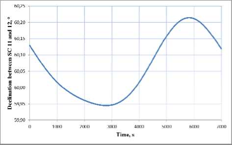
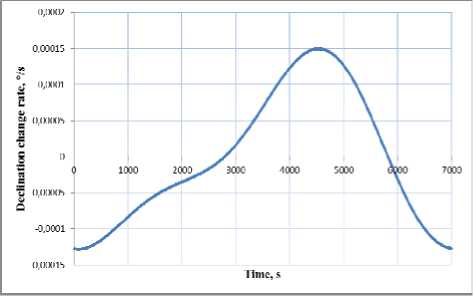
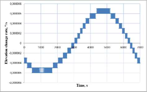
In fig. 5–7 are shown ballistic parameter variations (where subitem a) parameter, b) parameter change rate):
-
– Range – line-of-sight distance between SC [12]. Range change rate;
-
– Declination – antenna direction angle from one SC to another measured from the direction to the Earth’s center. Declination change rate;
-
– Elevation – antenna direction angle from one SC to another measured from velocity vector in the clockwise direction. Elevation change rate.
We can put the calculations of SC antenna pointing ballistic parameters together. The range of parameter changing for IL in an orbit pass between SC № 11 and SC № 12 is listed in tab. 5.
We must point out that in the orbit pass SC № 11 and SC № 12 are constantly in the zone of mutual visibility -that is confirmed by the parameter of 100 %.
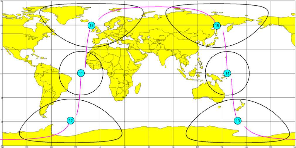
Fig. 3. Common RVZ in one orbital plane with IL within that plane
Рис. 3. Общая ЗРВ одной орбитальной плоскости при МЛС внутри плоскости
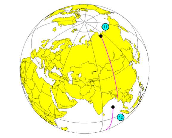
Fig. 4. The motion of two close-positioned SC № 11 and 12 in the first orbital plane
Рис. 4. Движение двух ближайших КА № 11 и 12 первой орбитальной плоскости
Table 4
SC № 11 and SC № 12 reference
|
Parameter |
SC № 11 |
SC № 12 |
|
Date |
31.05.2019 |
31.05.2019 |
|
MDT |
11:59:57 |
12:19:14 |
|
Coordinate Х, km |
7232.954011 |
6936.407866 |
|
Coordinate Y, km |
–3120.071909 |
–3714.968713 |
|
Coordinate Z, км |
0,0 |
0.0 |
|
Velocity Vx, km/s |
0.140334 |
0.171858 |
|
Velocity Vy, km/s |
0.325291 |
0.310911 |
|
Velocity Vz, km/s |
7.052965 |
7.060811 |
а b
Fig. 5. Ballistic parameter range:
а – range changing between SC № 11 and 12; в – range change range
Рис. 5. Баллистический параметр «дальность»:
а – изменение дальности между КА № 11 и 12;
б – скорость изменения дальности
a b
Fig. 6. Ballistic parameter declination:
а – declination changing between SC № 11 and 12; в – declination change rate
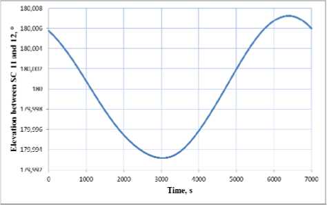
Fig. 7. Ballistic parameter elevation:
а – elevation change between SC № 11 and 12; в – elevation change rate
Рис. 6. Баллистический параметр «склонение»:
а – изменение склонения между КА № 11 и 12; б – скорость изменения склонения
b
Рис. 7. Баллистический параметр «восхождение»:
а – изменение восхождения между КА № 11 и 12; б – скорость изменения восхождения
Fig. 5–7 and tab. 5 data analysis demonstrates in the first place the stability of the basic parameters. Elevation is close to 0° in signal transmission from SC № 12 to SC № 11, and close to 180° in transmission from SC № 11 to SC № 12. The greatest variations are demonstrated by the SC antenna declination parameter.
Configuration 2 – IL between SC of adjacent planes № 1 and 2, № 2 and 3, № 3 and 4. Here is an analysis of IL configuration for SC moving in adjacent planes № 1 and 2, on example of SC № 12, 22, 23.
Tab. 6 presents the reference of SC № 22 and SC № 23, SC № 12 – in tab. 4.
Changing of IL ballistic parameters between SC within the orbital plane
Table 5
|
Parameter |
Range of parameter changing |
|
Range, km |
from 6658 to 9037 |
|
Range change rate, km/s |
from –0.03 to 0,03 |
|
Declination, ° |
from 54.37 to 65.36 |
|
Declination change rate, °/s |
from –0.001 to 0.001 |
|
Elevation, ° |
from 179.99 to 180.01 |
|
Elevation change rate, °/с |
from –0.00006 to 0.00006 |
|
SC mutual visibility period in an orbit pass, min |
115.9 (100 %) |
SC № 22 and № 23 reference
Table 6
|
Parameter |
SC № 22 |
SC № 23 |
|
Date |
31.05.2019 |
31.05.2019 |
|
MDT |
12:09:37 |
12:28:54 |
|
Coordinate Х, km |
7386,336533 |
7591.458385 |
|
Coordinate Y, km |
2724.447324 |
2091.536252 |
|
Coordinate Z, km |
0.0 |
0.0 |
|
Velocity Vx, km/s |
–0.127584 |
–0.086993 |
|
Velocity Vy, km/s |
0.341148 |
0.352760 |
|
Velocity Vz, km/s |
7.055772 |
7.054474 |
Changing of IL ballistic parameters between SC in adjacent planes № 1 и 2
Table 7
|
Parameter |
Range of parameter changing |
|
Range, km |
from 3800 to 7200 |
|
Range change rate, km/s |
from –3 to 3 |
|
Declination, ° |
from 63 to 77 |
|
Declination change rate, °/с |
from –0.05 to 0.05 |
|
Elevation, ° |
from –60 to 60; from 120 to 240 |
|
Elevation change rate, °/с |
from –0.4 to 0.15; from –0.15 to 0.15 |
|
SC mutual visibility period in an orbit pass, min |
115.9 (100 %) |

Fig. 8. SC motion in adjacent planes № 1 and 2
Рис. 8. Движение КА в соседних плоскостях № 1 и 2
SC № 31, 32 and 33 reference
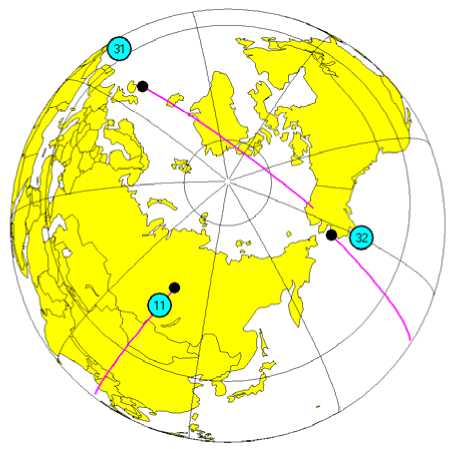
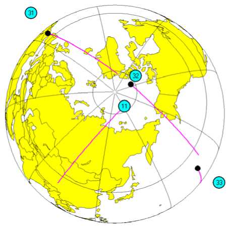
Fig. 9. SC orthogonal motion in planes № 1 and 3
Table 8
|
Parameter |
SC № 31 |
SC № 32 |
SC № 33 |
|
Date |
31.05.2019 |
31.05.2019 |
31.05.2019 |
|
MDT |
11:40:43 |
12:00:00 |
12:19:17 |
|
Coordinate Х, km |
2233.447140 |
2864,993939 |
3469.973938 |
|
Coordinate Y, km |
7544.938345 |
7337.622768 |
7062.144241 |
|
Coordinate Z, km |
0.0 |
0.0 |
0,0 |
|
Velocity Vx, km/s |
–0.354350 |
–0.342044 |
–0.328272 |
|
Velocity Vy, km/s |
0.099865 |
0.133551 |
0.166529 |
|
Velocity Vz, km/s |
7.059052 |
7.051298 |
7.059063 |
Fig. 8 shows the OC fragment, consisting of SC № 12 from the first orbital plane and SC № 22, SC № 23 from the second orbital plane, for the moment of their positioning in the equator and pole areas. During the full orbit pass SC № 12 motion is mostly parallel to SC № 22, SC № 23 is also parallel; SC routes get crossed only in the pole areas.
We can put together the calculations of SC antenna pointing parameters for planes № 1 and 2. The range of IL parameter changing is listed in tab. 7.
We must point out that the sampled SC № 12, SC № 22 and SC № 23 continuously remain in the mutual visibility zone.
The IL in tab. 7 compared to the IL of one orbital plane (tab. 5) shows the increasing dynamics of declination and elevation angles changing. Here the declination change rate increased by 50 times (0.001 and 0.05), and the elevation change rate increased from 0.00006 °/s to 0.15°/s.
We have the best conditions for information transmission in the equator area. There the information can be transmitted in chain order to all 4 planes of the system.
It should be noted that for the sampled OC of 24 SC at 1500 km altitude, the common IL including configurations 1 and 2 is self-supporting (provides general linking of all SC in the OC).
Configuration 3 – IL between SC in planes № 1 and 3, № 2 and 4. Let us review the IL configuration, in which SC move almost transversely, at the example of orbital planes № 1 and 3.
Tab. 8, in addition to Tab. 4, presents SC № 31, 32, 33 reference.
Here the mutual visibility of SC in different planes occurs at high latitudes.
Each SC of one orbital plane can see from two to three SC of another orbital plane. We can point out that the time of simultaneous visibility of three SC is not long. We analyze the example of IL for SC № 11 of the first orbital plane, and SC № 31, 32 and 33 of the third orbital plane (fig. 9).
IL parameter changes between SC № 11 and SC № 31, 32, 33 are listed in tab. 9.
In motion of SC № 11 relative to SC № 31, 32 and 33, mutual visibility period or IL operational time of the SC is rather long, mainly close to revolution half-period.
Comparison of this IL parameters (tab. 9) with IL in one orbital plane (tab. 5) and IL in adjacent orbital planes (tab. 7) demonstrates still more growing dynamics when the declination and elevation angles get changed. Now the declination change rate comes up to 0.17 °/s, and elevation change rate – to 0.55 °/s.
Configuration 4 - IL between SC in planes № 1 and 4. Here is an analysis of IL configuration in planes № 1 and 4. Its main feature is the SC oncoming motion.
During the revolution half-period a SC of one orbital plane runs across all other SC of another orbital plane.
The dynamics of the SC route intersection depends on the Earth's surface latitude, over which the SC route intersection takes place. In this case, there may be three variants: equator zone, middle latitudes and high latitudes.
Let us review the IL on the example of SC № 11 of the first orbital plane and all six SC of the fourth orbital plane.
Tab. 10 shows the reference of SC № 41-46, SC № 11 - in tab. 4.
SC of one orbital plane can see from one to three SC of another orbital plane at the same time. Fig. 10 shows SC positioning in equator and pole areas.
Рис. 9. Ортогональное движение КА в плоскостях № 1 и 3
Table 9
|
Parameter |
Range of parameter changing |
||
|
SC № 11 and 31 |
SC № 11 and 32 |
SC № 11 and 33 |
|
|
Range, km |
from 6000 to 9200 |
from 500 to 9200 |
from 5000 to 9200 |
|
Range change rate, km/s |
from –6 to 6 |
from -9 до +9 |
from –6.3 to +6.3 |
|
Declination, ° |
from 54 to 68 |
from 54 to 88 |
from 54 to 71 |
|
Declination change rate, °/с |
from –0.14 to 0.14 |
from –0.17 to 0.17 |
from –0.15 to 0.15 |
|
Elevation, ° |
from 7 to –93; from 170 to 267 |
from 60 to –120; from 140 to 310 |
from 82 to 190; from –20 to 100 |
|
Elevation change rate, °/с |
from –0.5 to 0.05 |
from –0.18 to 0.06 |
from –0.05 to 0.55 |
|
SC mutual visibility period in an orbit pass, min |
50.1 (43.2 %) |
71.1 (61.3 %) |
56.0 (48.3 %) |
Changing of IL ballistic parameters between SC in planes № 1 and 3
Table 10
References Spacecraft motion in a low circular orbit in establishing intersatellite link
- Zolkin I. A., Ignatovich E. I., Shekutiev A. F., Bolkunov A. I. [Intersatellite communications as a key element of GNSS technologies]. Polyot. 2012, No. 4, P. 29–33 (In Russ.).
- Katsura A. V., Akzigitov A. R., Andronov A. S., Strokov D. E., Akzigitov R. A. [Development of an onboard device for satellite monitoring of aircraft]. Vestnik SibGAU. 2016, Vol. 17, No. 1, P. 125–130 (In Russ.).
- Krylov A. Sputnikovye sistemy sviazi i veshchaniia. Sostoianie i perspektivy razvitiia [Satellite communication and broadcasting systems. Status and prospects of development]. Moscow, 2014, 182 p.
- Vecytomov V. A. [Inter-Satellite link IIM range]. Materialy XX Mezhdunar. nauch. konf. “Reshetnevskie chteniya” [Materials XVIII Intern. Scientific. Conf. “Reshetnev reading”]. Krasnoyarsk, 2014, Vol. 1, P. 63–65 (In Russ.).
- Sanjay Kumar. Wireless Communication the fundamental and advanced concepts, Birla Institute of Technology Mesra, Ranchi, India, Published River Publ., 2015, P. 790.
- Chini P., Giambene G., Kota S. A survey on mobile satellite systems. International journal of satellite communications. 2010, Vol. 28, P. 29–57.
- Kolovsky I. K., Podolyakin V. N., Shmakov D. N. [Ballistic building of the «Gonets-M» orbital constellation for ensuring the inter-satellite link inside orbital plane]. Materialy XX Mezhdunar. nauch. konf. “Reshetnevskie chteniya” [Materials XXII Intern. Scientific. Conf. “Reshetnev reading”]. Krasnoyarsk, 2018, Vol. 1, P. 30–31.
- Vygodskiy M. Ya. Spravochnik po elementarnoy matematike [The handbook on elementary mathematics]. Moscow, AST, Astrel Publ., 2014, 509 p.
- El’yasberg P. E. Vvedenie v teoriyu poleta iskusstvennogo sputnika Zemli [Introduction to the theory of flight satellite]. Moscow, URSS Publ., 2015, 544 p.
- Makarenko S. I. Descriptive model of Iridium satellite communication system. System of control, communication and security. 2018, Vol. 4, P. 1–34.
- Gibalina Z. S., Fadeev V. A. Optical inter-satellite link in comparison with RF case in CUBESAT system. Zhurnal Radioelektroniki. Magazine of radioelectronics. 2017, Vol. 10, P. 12.
- Moskaliev A. N., Muratov D. S., Serenkov V. I. [Evaluation ephemeris navigation spacecraft of GLONASS measurements inter-satellite radiolines]. Materialy XI Mezhdunar. nauch.-praktich. konf. “Aktualnye problem aviacii i kosmonavtiki” [Materials XI Intern. Scientific.-Pract. Conf. “Pressing problems of the aviation and astronautics”]. 2015, Vol. 1, P. 74–76.
- Shirobokov V. V., Shinkarenko A. F. [An approach to the organization inter-satellite interaction in distributed computing structure of the orbital group microsatellites]. Trudy voenno-kosmicheskoy akademii im. A. F. Mozhaiskogo. 2015, Vol. 646, P. 77–82.
- Vygonskiy Yu. G., Mukhin V. A., Kuzovnikov A. V., Somov V. G. [Combined satellite communications system serving ground and space users based on geosynchronous orbit data relay satellites equipped with multiple beam antennas]. Fundamental'nyye issledovaniya. 2014, No. 9-5, P. 965–970 (In Russ.).
- Mukhin V. A. Sposob postroyeniya kosmicheskoy sistemy retranslyatsii s ispol'zovaniyem geosinkhronnykh sputnikov-retranslyatorov [A method of constructing a space relay system using geosynchronous relay satellites]. RF patent № 2366086, MPK Н04В.
