Static characteristics of active hydrostatic two-row radial bearing with restriction of output lubricant flow

Author: Kodnyanko Vladimir A.
Journal: Журнал Сибирского федерального университета. Серия: Техника и технологии @technologies-sfu
Article in issue: 1 т.5, 2012.
Free access
The design of active hydrostatic radial bearing with smooth cylindrical surfaces and lubricant output flow restrictors in the form of movable rings on membrane suspension is presented. The device is several times less power-consuming compared with known devices of flow control. The bearing has a negative and zero compliance (infinite stiffness), and therefore can be used in machine tools to suppress the negative influence of elastic system deformation on the accuracy of processing. On the basis of two-dimensional model of lubricant flow developed a mathematical model, method and procedure for calculating the bearing load capacity and flow rate. It is established, that the calculation of static characteristics of bearing in the entire range of operating loads can be correctly performed only on the base of two-dimensional model. For small eccentricities the characteristic of zero and negative compliance can be calculated with sufficient accuracy by the simplified method, based on one-dimensional motion of lubricant flow. Bearing of zero or negative compliance have load capacity range, which is 20 - 50% more than conventional bearings of the same overall dimensions. The setting of input throttling slits resistance decisive influence on the optimal static characteristics of the bearing. The optimal values of its resistance for conventional and active bearing are practically identical.
Energy-saving, hydrostatic bearing, zero compliance, negative compliance, infinite stiffness, smooth cylindrical surface
Short address: https://sciup.org/146114634
IDR: 146114634 | UDC: 621.9:
Статические характеристики активного гидростатического двухрядного радиального подшипника с ограничением выходного потока смазки
Рассмотрена конструкция активного гидростатического радиального подшипника с гладкими цилиндрическими рабочими поверхностями и ограничителями выходного смазочного потока смазки в виде подвижных колец с мембранным подвесом. Устройство в несколько раз менее энергоемко по сравнению c известными устройствами с регуляторами расхода. Подшипник обладает отрицательной и нулевой податливостью (бесконечной жесткостью), поэтому может быть использован в металлорежущих станках для подавления негативного влияния деформации упругой системы на точность обработки. На основе двухмерной модели смазочного потока разработана математическая модель, метод и методика расчета несущей способности и расхода смазки подшипника. Установлено, что расчет статических характеристик подшипника во всем диапазоне действующих нагрузок может быть корректно выполнен только на основе двухмерной модели. При малых эксцентриситетах характеристики нулевой и отрицательной податливости могут быть с удовлетворительной точностью рассчитаны по упрощенной методике, базирующейся на одномерном движении смазочного потока. Подшипники нулевой и отрицательной податливости обладают грузоподъемностью, которая на 20 - 50 % больше, чем у обычных подшипников тех же габаритных размеров. Настройка гидравлического сопротивления входной питающей щели решающим образом влияет на оптимальные статические характеристики подшипника. Оптимальные значения сопротивления щели для обычных и активных подшипников практически совпадают.
Text of the scientific article Static characteristics of active hydrostatic two-row radial bearing with restriction of output lubricant flow
In the radial gas and hydrostatic bearings (HB) with input flow regulators (AGH-IR), which are able to exert an active influence on the performance of important characteristics, in particular the significant decrease in compliance of the load-carrying lubricant film to zero and negative values [1]. These bearings can be used in machine tools in order to diminish the negative impact of the deformation of the elastic system on accuracy. The active bearing of this type characterized by two major disadvantages – to maintain their working ability requires a considerable flow rate [2] and in this connection bearing shafts may make limited movement only.
In [3], an opposite principle to control the flow of hydraulic fluid, which is used in bearings the restrictors of output lubricant flow (AGH-OR). In comparison with the AGH-IR such designs have a
much better static characteristics and have no disadvantages of AGH-IR [4]. In addition, for example, not full scope radial or open thrust AGH-OR with little or no increase in energy consumption can make a significant movement of mobile elements, in which the AGH-IR would obviously inoperable [5]. This unique property of AGH-OR opens up the possibility of their to use not only in machine tools, but in micro shock absorbers, energy-saving hovercrafts, low flow rate aerostatic suspensions of ground and suspended trains and high-load machines.
In [4] presents the method of calculating the characteristics profiled AGH-OR on the basis of one-dimensional flow model of working fluid in a thin lubricating gaps. In conventional radial bearing more often used smooth cylindrical compounds, which are distinguished by simplicity of design and manufacturing technology. For such GH one-dimensional models are not suitable because it does not take into account the influence of circumferential lubricant overflows on the characteristics of bearings, which leads to significant errors of calculations. In this paper presents design, mathematical model, calculating procedure and results of study for radial hydrostatic bearing of this type with smooth cylindrical working surfaces.
In Fig. 1 shows a longitudinal section of the bearing. The design contains a shaft 2 and the housing 1 with a throttling slits 3, through which fluid from source under pressure p S enters into the bearing. At the ends of housing there are circular protrusions on the inner side of which are a ring-type membranes 4, forming with the housing and protrusions the cavity 5, hydraulically connected with the slits 3. To the membrane tightly attached rigid rings 6 with cylindrical surfaces forming with the housing axial gaps 8. The inner surface of the housing 1 and the surface of shaft 2 form slot gap 9 of main loadcarrying lubricant film of thickness h , and the surface of the shaft and ring elements 6 – end load-
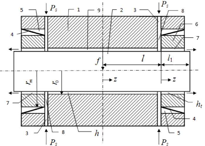
Fig. 1. Scheme of bearing carrying lubricant film with thickness ht. Membrane hermetically attached to the outer edge of the housing and by inner edge – to the rings.
Bearing operates as follows. The pumped lubricant, overcoming the hydraulic resistance of slits 3, comes into a thin lubricating gap of cavities 5 and through the channels 8 in carrying lubricating gaps 9 and 7, and then flows from the bearing. Hydraulic forces which created by pressure on the membrane in cavities 5 and gaps 7, counterbalanced by force of elastic membrane material deformation. The integral reaction of the pressure forces on the rings 6 in gaps of the cavities 5 is always greater than the same reaction from side of gaps 7, as can be verified by analyzing the pressure distribution diagrams of lubrication in these gaps. Therefore rings 6 will always carry opposite direction against the direction of external force vector f , thereby creating a greater obstruction for lubricant outflow from the bearing and raising the hydraulic force of the impact on displaced under the load shaft. Depending on the membrane flexibility, affecting the motion characteristics of rings 6, it provides decrease of capacity to zero and negative values.
In modeling of AGH-OR work expected that observed parallelism of axes housing, shaft and movable rings (Fig. 1). Calculations were carried out using dimensionless quantities. For the scales adopted: radius r 0 of shaft – for linear dimensions, supply pressure p S – for pressures, π r 02 p S – for loads and forces, π h 03 p s / 6 µ – for volumetric flow rates, h 0 – for gaps, clearances and eccentricities of moving parts, where h 0 – thickness h of lubricant film in the coaxial arrangement of movable elements (at f = 0), μ – viscosity of lubricant. Dimensionless variables are indicated by capital letters.
Due to the symmetry of bearing was considered his right half (Fig. 1). For the central ( c -area) and end ( t -area) parts of the base gap and for gap of cavity 5 ( m -area), introduced local coordinate systems. Longitudinal coordinate Z is measured from the left edge of areas, and the circumferential coordinate φ from the line in which indicated vector of external force f .
Function of dimensionless pressure P ( Z , φ) in thin lubricating gaps for an incompressible lubricant satisfies the stationary differential Reynolds equation [6]
Since the cavity 5 is stagnant, then at any point φj on the circle of pairing membranes and bearing housing, flow rate is absent
ϕ j + δ
Q m ( L 1 , ϕ j ) =- Rm H m 3 ( L 1 , ϕ ) ∂ P ( L 1 , ϕ ) d ϕ = 0,
2πϕj-δ ∂Z where R – dimensionless outer radius of rings.
m
It is also clear that in the absence of hydraulic resistance of lubricant flow in the channel 8 at the entrance to the lubricating gaps same functions of pressure are equal
P c ( L 2 , ϕ ) = P t (0, ϕ ) = P m (0, ϕ ) = P n ( ϕ ), (4)
аnd balance of the dimensionless flow rates of working fluid in this section is determined by the q
Q n ( ϕ j )- Q m (0, ϕ j )- Q t (0, ϕ j )+ Q c ( L 2 , ϕ j )=0. (5)
Here index n refers to the channel 8, L 2 = L – L 1 – length of c -area.
In mathematical modeling also suggested that the width of the movable ring is small compared to its diameter. This assumption is justified by the fact that the narrow ends of the bearings have high carrying load, lower radial and angular compliance. The presence of the narrow ends allowed neglect the influence of circumferential overflows in the lubrication of t -area and m -area, i. e. assume that for them ∂ P /∂φ = 0. Simplifies equation (1) and its solution for t -area, taking into (2) can be found as a function
L 1 - Z ( )
Pt ( Z , ϕ ) = Pn ( ϕ ) .
L 1
Relative to coordinate Z linear is also the general solution of the simplified equation (1) for m -area, and (3) is equal
∂ P m ( L 1 , ϕ ) = 0
∂ z .
In accordance with condition (4) solution of simplified equation (1) for m -area obtained as
P m ( Z , ф) = P n (ф ). (7)
At c -area mentioned assumption can’t be applied, so solution of equation (1) founded by numerical finite-difference method [7]. To do this, the intervals [0, L ] and [0, π] broke an even number n and m equal parts of length ν = L 2 / n and τ = π/ m , respectively.
Split points and function P values in finite-difference grid nodes are
Z = v ( i = 0,1,2,..., n ), P j = jT ( j = 0,1,2,..., m), P = P ( Z„V j ).
Equation (1) presented in a more convenient form
-3 dH dP+622P+»2P . 0, h аф дф д2ф ё2z
For interior points of area derivatives changed on symmetric finite-difference relations [6]
a (P + 1 - P + 1) + ( P + 1 - 2 P + P — 1) + в P . i - 2 P + P\ ) = 0, (8)
i i i i i i+1 i i-u where
3TsSin (ф , ) a = -T---z—r^T,
1 2 [1 - sCos ( ^ )J

The desired pressure in nodes presented by the vectors
P = ( P i 0 , P 1 , P P m-1, P m ) , ( i = 0,1,2,..., n )
and by means of (8) described in matrix-vector form where
|
P i — 1 |
+ AP + P^. i i + 1 |
= 0, |
( i = 1,2,3 |
..., n — 1), |
(9) |
||||
|
Г 11 |
2 |
0 |
0 ... |
0 |
0 |
0 " |
|||
|
1 - а1 |
n |
1 + a 1 |
0 ... |
0 |
0 |
0 |
|||
|
A = |
1 в |
0 ... |
1 - a 2 .. |
Л ... |
1 + a 2 ... 2 ... ... |
0 ... |
0 ... |
0 ... |
, n = -2(1 + в ). |
|
0 L 0 |
0 0 |
0 0 |
0 ... 0 ... |
1 - a m _ 1 0 |
n 2 |
1 + a m - 1 П . |
|||
System of linear equations (9) is solved by matrix sweep method [7], using the recurrence formulas
P-i = XP + Y, (i = 1,2,3,...,n -1), where Xi, Yi – sweep matrixes and vectors.
The system of equations (9) supplemented by vector equation
- P0 + 4 P1 - 3 P2 = 0, which is a finite-difference analogue of the first boundary condition (2) for Z = 0.
In system of two linear matrix equations (11) and (10) for i = 1, after elimination of P 2 found
P0 = |2 E +1 л| P1,(12)
I 2 J where E – identity matrix.
Comparing (12), (10) for i = 1, found
r
1 [ 2 J, 1)
After substituting (10) into (9) found the recurrence formulas
X.+1 =-(A+X)-1, Y+1 = Xi+Y, (i = 1,2,...,n-1).
Next, performed a direct sweep by (13) and (14) and were found sweep matrixes X 2, X 3, …, X n and vectors Y 2 , Y 3 , …, Y n .
For perform of reverse sweep requires vector P n. To determine it used the flow rate balance equation (5) through the gaps in narrow sectors [φ j – τ/2, φ j + τ/2]. The general formula for determining flow rate through a cross section Z is given by [6]
т
^ j + 2
Qkj(Z) = -RL j HW8P(Z,ф) dф,(15)
2V тd where Rk – inner or outer radius of the ring (inner radius Rk = 1, outer radius Rk = Rm).
Since the integration step τ is a small quantity, instead of (15) used simplified formula
T R k з 5 P k ( Z , ф j )
Qk j (Z ) =H к (Фi)------------■
’ 2-5
Dependences (6) and (7) provided a formula for local flow rates at the inlet of t-area j=HP(17)
So far as function (7) does not depend on the longitudinal coordinate, in accordance with (16) local flow rates at the entrance of cavity 5
Qm ,j(0) = 0(
Local flow rates on the boundary Z = L 2 determined by means of the finite-difference formula for the derivative at the right endpoint [8]
8P(L2,Фj) = 3Pn -4РП-1+ РП-2(19)
dZ 2v'
Substituting (19) in (16), found
Qc,j(L2) = -тH3(3Pn -4РП-1 + РП-2)■
nv
In the absence of external load the pressure in channel (8) and at entrance to all areas does not depend of circumferential coordinate and is equal to
Р П = x = Const , ( j = 0,1,2,..., m - 1, m ) ,
So full flow rate through the throttling slit is determined by the formula [6]
Q n = A n ( 1 - X ) .
In the coaxial arrangement of the movable elements in c -area Qc = 0 and in t -area in view of (6) and (15) total flow rate through one end of the bearing is equal to
Qt о = -
I dv = X H^ 0 .
L 1
Substituting founded flow rate dependences in equation (5), obtained a formula for calculating the parameter of throttling slit
A (1 - X = XH 3 , A = XH (23)
" ( ) L 1 0 ' L ' (1 - ■ )
Taking this into account the local flow rates through the throttling slit are determined by the formula
Q i - ' 1 P '
After substituting (17), (18) (20), (24) into equation (15) had obtained a system of equations
A ( 1 - P1 ) - H j PJ - H j ( 3 P - 4 PJ , + PjA = 0.
( " 1 L i " 2v ( n " - 1 " 1
(1' = 0,1,2,---, m )
In matrix-vector form (25) is equal to
BP n — 4 P n - 1 + P n - 2 = С ,
where B diagonal matrix, C – vector
B = diag { b 0 , b i , b 2 ,..., b m }, C = A n ( c 0, c„ c 2 ,..., C m ),
c - 2V сj H3j ,
b 3+ ( +^ ’Л j jn .
I L 1 J
Equations (9), (10) for i = n – 1 and (26) are given a system of matrix equations
Pn + APn—1 + Pn—2 0, fnPn + Yn = Pn—1, BP - 4 P , + P ? = С i n n-1 n-2
for determination of unknown vector
P n = ( B - E - DX n )- 1 ( C + DY n ) , D = 4 E + A.
Using (10) performed reverse sweep and founded vectors Pn -1, Pn -2,…, P 1, P 0.
The resulting solution allowed define load-carrying capacity of lubricating area by the general formula [6]
П a
W k = —k- Cos^ P k ( Z , Ф ) dZdV , n 0 J0
where a – length of area.
For t -area according to (6)
2 a L1 L-Z L*C L,
Wt = - J Cos^ Pn (Ф) dZdV = -Ц Pn (Ф)CosVdV = -1 J,, n 0 0O L, n 00 n
where
п
J 1 = j P n (ф ) Cospdp.
0
For m -area according to (7)
7/? п L ЭИ Т
Wm = mJ Cos-рф Pn (ф) dZdф = —m-1 J„ п 0 0 п
Integral (27) calculated by mains of quadrature Simpson's rule [9]
m
J i = 7 S k j P i Cos ( J' )• ( k j = I.4-2-4-2 2.4,«-
3 j = 0
For c -area in the calculation of the load capacity used cubature Simpson’s rule [10]
2 n L2 2vt m\ n kCos(T )£ kP ■ =0
W c =
-j Cos^ P ( Z , ф") dZdф £
* 0 0 9 n %0 L
Full load capacity of bearing calculated by formula
W = 2 ( W t + W c ) .
To determine the full volumetric flow rate through the bearing used formula
П П .m
Q = 4 Q t = - - J H t -P-dV = — J H 0 P„dV = ^ kH ^j P j .
П 0 d Z n L1 0 3 n L 1 1 = 0
The force balance equation of the ring, commits to the membrane-hydrostatic suspension small radial displacement, based on the use of Hooke's law [11]. As mentioned above, the direction of ring movement and external force vector are opposite. Therefore, the eccentricity ε has non-positive value (ε m ≤ 0) and is associated with the acting forces on the ring by relation
F m - W m + W t = 0, (28)
where m 2Ym °m ,
– elastic force of membrane, K m = Const – dimensionless compliance of the membrane material.
In calculations were used the input dimensionless parameters: pressure coefficient χ ∈ [0, 1], lengths L and L 1, ring radius Rm , clearances Ht 0 and Hm 0, compliance coefficient of membranes Km , n and m numbers of segments for finite-difference grid. Main performance characteristics of interest in the present study are load capacity W , flow rate Q , eccentricities ε and ε t .
In calculation of dependences were varied eccentricity ε m with small step throughout the range [– Hm 0, 0]. Successively changing this parameter and using obvious connection of eccentricities
Vladimir A. Kodnyanko. Static Characteristics of Active Hydrostatic Two-Row Radial Bearing with Restriction... е = е m + е t for each fixed εm by bisection numerical method [12] found the solution of nonlinear equation (28) in form
G (г t ) = F m - W m + W t = 0 (29)
for one unknown variable ε t ∈ [ a , b ], where a = 0, b = H t 0 . Process was stopped when b – a < 10 -5 .
In Fig. 2 shows plots of function G (ε t ) of equation (29) for different values of eccentricity ε m .
It is seen that the curves on the interval ε t ∈ [0, H t 0 ] are continuous, have a unique point of intersection with the horizontal axis (the root of the equation) or on this segment does not intersect it at all (no root). The latter refers to specific cases of contact of rings working surfaces and the shaft, in which the bearing is losing efficiency.
The effect on the characteristics of the circumferential lubrication overflows in interrow area can be seen in Fig. 3, which shows the comparative dependences e( W), obtained in [4] on the basis of one-dimensional model (1-D model) and calculated out in this work by using two-dimensional model lubricant flow (2-D model).
It is seen that for bearings with smooth working surfaces using a one-dimensional flow model of interrow area gives overestimation of load capacity of 1.5 – 2 times.
Distortion of characteristics is particularly noticeable at moderate and high loads and for low capacity Km of membranes, when bearing still has positive compliance K = ∂ε/∂ W . With the increase K m error in the calculation of compliance K in small eccentricities area observably decreases and at bearing work on modes of zero and negative susceptibility ( K ≤ 0) one-dimensional model gives fairly satisfactory results.
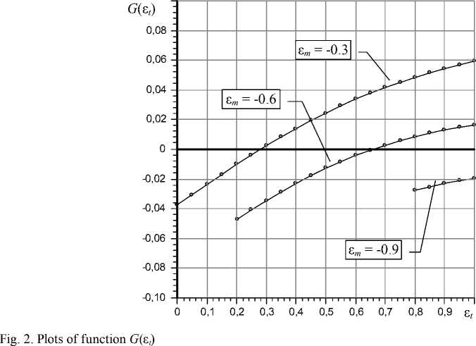
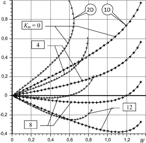
Fig. 3. Comparative dependences ε( W ) for a smooth (2-D) and profiled (1-D) bearings for various values of membrane compliance K m , χ = 0.52, L = 1.5, L 1 = 0.3, R m = 1.2, H t 0 = 1
For moderate and large eccentricities the error is large for any values of the parameter K m . An analysis of the data for the various teachings of elongation L, at high loads, even for short bearing ( L < 0.6) on the charts there is a noticeable difference curves.
Analysis of the calculated dependences shows that the decisive influence on the static characteristics has a pressure parameter χ, which defines setting for input throttling slit resistance. It is known that for conventional bearing function of eccentricity ε(χ), the load capacity W (χ) and compliance K (χ) are of an extreme character.
In Fig. 3 shows the curves of ε(χ) for being studied bearing.
It is seen that they have the same character. The calculations showed that, regardless of displacement of mobile elements minimum eccentricity is provided at approximately the same value of the parameter χ opt .
So for the graphs presented in Fig. 4, the smallest value of the eccentricity and compliance occurs at χ = 0.52. The only parameter that significantly affects the optimal value of χ, is a clearance H t 0 . Thus, when Ht 0 = 1.5 optimal χopt = 0.24, at Ht 0 = 1.25 χopt = 0.42, at Ht 0 = 0.8 χopt = 0.68.
Attention is drawn to the fact that an increase in K m significantly expands the range of perceived bearing loads (Fig. 3). In Fig. 5 shows the curves that show the relationship with the capacity of the membranes K m percentage T of increase the maximum load capacity W under maximum load ordinary bearing ( Km = 0).
From the Fig. 5 graphs show that the dependences T ( K m ) are extreme, i. e. for a fixed set of parameters it can specify a quite definite value of Km , in which the bearing will have the widest range of carrying loads.
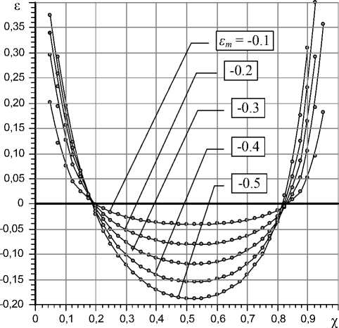
Fig. 4. Dependences ε (χ) for different values of the eccentricity ε m of rings L = 1.5, L 1 = 0.3, R m = 1.2, H t 0 = 1,
K m = 12
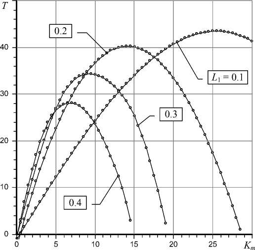
Fig. 5. Dependences T ( K m ) for different length L 1 of the rings, L = 1.5, R m = 1.2, H t 0 = 1
Decreasing width L 1 of rings increases the maximum value of this relationship. Thus, when L 1 = 0.4 the best result occurs when K m = 7, for L 1 = 0.3 K m = 9, at L 1 = 0.2 K m = 14, with L 1 = 0.1 K m = 25. For Fig. 5 data range of load capacity will be 28 – 43%. The increase of relative bearing length also enhances load range. So, when L = 2 T = 48%, with L = 3 T = 52%, with L ≥ 4 T = 55%.
This study results allow us to conclude that the correct calculation of static characteristics of hydrostatic radial bearings with smooth cylindrical surfaces and output flow rate restrictors over the entire range of operating loads can be carried out on the basis of two-dimensional model of lubricant flow only. However, for small eccentricities characteristics of bearing with zero or negative susceptibility can be calculated with sufficient accuracy by the simplified method, based on one-dimensional motion of lubricant flow [4]. Bearings with zero and negative compliances have capacity that is 20 – 50% more than conventional bearings of the same overall dimensions. The hydraulic resistance setting of input throttling slits decisive influence on the optimal static characteristics of the bearing. In this case the optimal values of resistance for conventional and active bearings are practically identical.
Final conclusion on the performance of bearings can be obtained on the basis of dynamic quality study and experimental investigation of its performance indicators.
-
[1] Kodnyanko V.A. Shatokhin S.N. // Engineering Science. 1978. № 6. P. 90–95
-
[2] Kodnyanko V.A., Shatokhin S.N. // Engineering Science. 1980. № 6. P 108–112.
-
[3] Pat. 2370680 (2008). Russian Federation. IPC. 2009. F16C 32/06. Bull. № 29.
-
[4] Kodnyanko V. A. / / Journal of Siberian Federal University. Machinery and technology. Krasnoyarsk, 2009. T. 3. № 3. P. 444–453.
-
[5] Kodnyanko V. A. / / Moscow, Moscow State Technical University Stankin. № 16. 2001. http:// magazine.stankin.ru/arch/n_16/index.shtml
-
[6] Constantinescu V.N. Gas lubrication. Moscow, Mashinostroenie. 1968. P. 709.
-
[7] Samarsky A. A., Gulin A.V. Numerical methods. Moscow, Nauka. 1989. P. 432.
-
[8] Demidovich B. P., Maron I. A., Shuvalova E. Z. Numerical Methods of Analysis / / Moscow, Fizmatgiz. 1963. 660 P.
-
[9] Dwight G. Tables of integrals and other mathematical formulas. Moscow, Nauka. 1973. 228 P.
-
[10] Kahaner D., Mouler C., Nash S. Numerical Methods and Software. Springer-Verlag. 2001. 575 P.
-
[11] . Sedov L. I. Continuum Mechanics. Moscow, Nauka. Vol 1. 1970. 452 P.
-
[12] . Krylov V. I., Babkov V. V. Monasyrsky P. I. Computational methods. Moscow, Nauka. 1976. 312 P.
Статические характеристики активного гидростатического двухрядного радиального подшипника с ограничением выходного потока смазки
Сибирский федеральный университет, Россия 660041, Красноярск, пр. Свободный, 79
Рассмотрена конструкция активного гидростатического радиального подшипника с гладкими цилиндрическими рабочими поверхностями и ограничителями выходного смазочного потока смазки в виде подвижных колец с мембранным подвесом. Устройство в несколько раз менее энергоемко по сравнению c известными устройствами с регуляторами расхода. Подшипник обладает отрицательной и нулевой податливостью (бесконечной жесткостью), поэтому может быть использован в металлорежущих станках для подавления негативного влияния деформации упругой системы на точность обработки.
На основе двухмерной модели смазочного потока разработана математическая модель, метод и методика расчета несущей способности и расхода смазки подшипника. Установлено, что расчет статических характеристик подшипника во всем диапазоне действующих нагрузок может быть корректно выполнен только на основе двухмерной модели. При малых эксцентриситетах характеристики нулевой и отрицательной податливости могут быть с удовлетворительной точностью рассчитаны по упрощенной методике, базирующейся на одномерном движении смазочного потока. Подшипники нулевой и отрицательной податливости обладают грузоподъемностью, которая на 20 – 50 % больше, чем у обычных подшипников тех же габаритных размеров. Настройка гидравлического сопротивления входной питающей щели решающим образом влияет на оптимальные статические характеристики подшипника. Оптимальные значения сопротивления щели для обычных и активных подшипников практически совпадают.
