Steganography on RGB Images Based on a “Matrix Pattern” using Random Blocks

Author: Amir Farhad Nilizadeh, Ahmad Reza Naghsh Nilchi
Journal: International Journal of Modern Education and Computer Science (IJMECS) @ijmecs
Article in issue: 4 vol.5, 2013.
Free access
In this paper, we describe a novel spatial domain method for steganography in RGB images where a secret message is embedded in the blue layer of certain blocks. In this algorithm, each block first chooses a unique t1xt2 matrix of pixels as a “matrix pattern” for each keyboard character, using the bit difference of neighbourhood pixels. Next, a secret message is embedded in the remaining part of the block, those without any role in the “matrix pattern” selection procedure. In this procedure, each pattern sums up with the blue layer of the image. For increasing the security, blocks are chosen randomly using a random generator. The results show that this algorithm is highly resistant against the frequency and spatial domain attacks including RS, Sample pair, X2 and DCT based attacks. In addition, the proposed algorithm could provide more than 84.26 times of capacity comparing with a competitive method. Moreover, the results indicated that stego-image has almost 1.73 times better transparency than the competitive algorithm.
Steganography, Stego-image, Matrix pattern, Stego-matrix
Short address: https://sciup.org/15014536
IDR: 15014536
Text of the scientific article Steganography on RGB Images Based on a “Matrix Pattern” using Random Blocks
Published Online May 2013 in MECS DOI: 10.5815/ijmecs.2013.04.02
In modern world, the security of information that transmits in the Internet is one of the most important and major aspects in digital communication. Two major techniques that are used to secure information are cryptography [1] and steganography [2] and could be used together, as cryptography scrambles the message, and steganography hides the scrambled message in a cover, such as an image, video, audio, text, etc., to enhance the security, even further.
Among the covers, images are the most popular medium transmitted through the Internet. Images could provide plenty of space for embedding secret messages. As a result, many algorithms are proposed using images as cover medium in steganography.
In this paper we present a new efficient method in steganography based on “matrix pattern” that has a good capacity, transparency and security. A steganography system consists of the following components [3, 4]:
Cover Image: It is an image that secures the secret message, and is used as a cover for transmitting the message.
Message: It refers to information that is hidden in a cover image. Message can be a text, image, audio or any digital items. In this paper, the message can be a text or any cipher text that is changed to keyboard characters.
Stego-image: It is an image that contains the secret message after using the steganography.
Steganography key: It refers to a password/key that may be used by steganography algorithms for embedding data in a cover image or extracting data from stego-image. This element is not an essential part of a steganography system.
In a steganography system, first, the secret message is embedded in an image (cover) with an algorithm and produces a stego-image, and then stego-image may be sent to the receiver via an unsecure communication channel, such as Internet. The receiver then could extract the message from the stego-image.
Image based steganography maybe done in either spatial domain or frequency domain of the cover image [5]. In the spatial domain, secret message is embedded directly in pixels of image; one of the easiest and well known algorithms in this domain is LSB. In this algorithm, message is embedded in the least significant bit of pixels. In the frequency domain algorithms, the secret message is hidden in the frequency domain coefficients of the cover image; algorithms in this domain usually use DCT, FFT or Wavelet transform methods [6, 7].
Steganography algorithms should have following some properties [8, 9]:
Security: Hidden information embedded in the stego-image could not be recognized. Having a high security is the major aim of any steganography algorithm.
Capacity: the maximum size of that digital space that could be used to hide messages in an image.
Transparency: measures the lack of visual changes between cover image and stego-image; thus, the lower this is, the better the transparency.
Robustness: measures both the message detection ability by receiver, and the resistance against conventional attacks including compressing, scaling, adding noise, etc.
Computation Complexity: indicates the process time that the algorithm requires for embedding and extracting secret messages.
Between these parameters, capacity and robustness are usually against each other; if we increase capacity the robustness decreases and vice a versa [10].
This paper is organized as follows. In the next section, the proposed algorithm to embed data into an image is presented. In this section, first a block selection method is offered and then an algorithm to generate “matrix patterns” is presented. Then, the methodology to hide the secret message is discussed. Next, the decoding part of the algorithm on the receiver side is presented. Later, the implementation of all parts of the algorithm is discussed.
The following section includes discussion on the capacity of the algorithm and its dependency on other parameters is presented. Then, using statistical results on different parameters, an ameliorated capacity is obtained.
Next section the results on different steganalysis methods are presented and parameters such as Regular Singular (RS), Sample Pair (SP), Chi Square (X2), Pixel Value Differencing (PVD), and Discrete Cosine Transform (DCT) attacks are evaluated and the performance of our algorithm in the presences of these attacks are reported.
Finally, our algorithm is evaluated and compared with a similar algorithm in the next section.
-
II. Proposed algorithm
In this paper, a novel data embedding method is presented. An algorithm for selecting blocks is first described. Then, an explanation on how “matrix patterns” are chosen in each block is given. Next, a new algorithm for embedding and extracting hidden messages is offered.
-
A. Block selection
For steganography in spatial domain, selecting a suitable image area is a major task. A usual method is to embed the message in the least significant bits (LSB) of image pixels. This is because changing LSBs does not affect the image’s visualization much; and so, it provides a good transparency for stego-image. However, knowing this allows many steganalysis algorithms to detect or destroy the hidden messages. In this paper, the secret message is embedded in the four bits of blue layer -- excluding these LSBs -- namely 3rd through 6th bits of pixels, albeit mostly in the 3rd and 4th bit locations. This is because, as we explained later, our algorithm uses bit difference between neighbour pixels. Since 5th and 6th bits differences are often the same, algorithm seldom changes these bit values at these two locations. This parameter gives the algorithm a good resistance against the steganalysis attacks targeting the LSBs. In addition, because of choosing the blue layer of the images which have the least effect on brightness, stego-image would still keep its transparency.
For increasing the security and robustness of a stego-image, a pseudo-random generator is used for choosing random square blocks out of cover image. These picked random numbers and the sizes of chosen blocks are hidden in the cover image while embedding the secret message as described later.
Fig. 1 shows a sample 60x60 block of baboon in red square is picked; and Fig. 2 shows the enlarged version of this block before and after implementing our steganography algorithm. In this block 540 characters are hidden.
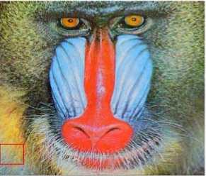
Figure 1. A red square sample block in the baboon image used to hide information.
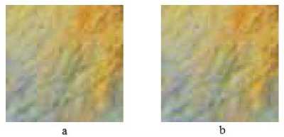
Figure 2. The enlarged version of the red square block shown in baboon image of Fig. 1 before and after embedment: a) cover block, b) stego block.
-
B. “Matrix Pattern” generation algorithm
After randomly selecting the blocks in the image, the message is translated to a “matrix pattern”. In a previous work, static “matrix patterns” of the hidden message’s characters are manually picked and used to hide it in all parts of the cover image, without considering the pattern changes of the image textures in different part of the image [11]. This, however, compromises the security of the method since “matrix patterns” in different textures have different visual effects. As a result, an attacker could easily visualize alterations in the image and so to decode or destroy the secret message with fewer efforts.
In order to resolve this problem, we propose to automatically identify and assign 49 unique but random “matrix patterns” in several blocks in the cover image. They are generated using the image’s texture information of each block and so, dynamically changes from block to block. 48 out of 49 “matrix patterns” discussed above, are assigned as the keyboard characters consisting 26 English characters, 10 numbers, and 12 keyboard special characters. We also assign one “matrix patterns” designated as “the end of the message” sign. The algorithm is as follows.
Let’s assume BxB pixels blocks as the building blocks in the cover image. Let also assume that t 1 and t 2 are the size of row and column of each “matrix pattern” inside the BxB building blocks, respectively. The t 1 xt 2 “matrix patterns” are located inside the building block starting from upper left side of each block. That is, the first t 1 xt 2 matrix in the upper left side of the block, which is established in Fig. 3.1, is assumed to be the first “matrix pattern”, representing the first character of the hidden message.
a (0,0) ... a (0, 1 2 )
a ( 1 1 ,0) • • • a ( 1 1 , 1 2 )
Figure 3.1. The first t1xt2 matrix in a sample block
As the first step in generating “matrix patterns” process, the RGB image is changed to an intensity image, then the first three least significant bits of each pixel, which are usually affected by spatial domain attacks in most steganalysis, are ignored, as we discussed earlier. This allows increasing the security and robustness of our algorithm. Then, all elements of the 1st row of the matrix are set to zero. Next, the bit difference between the elements in the 1st row through the t 1 th row of the matrix is calculated to generate “matrix pattern”. The algorithm’s pseudo-code is shown in Table I.
TABLE I. A SUBPROGRAM PSEUDO-CODE FOR PRODUCING A “MATRIX PATTERN”
for i = 0:t1
for j = 0: t 2
{ if (mod(i, ti) == 0)
a´ (i, j) = 0;
else a´ (i, j) = a (i, j) –a (i- 1, j);
end if
}
The result for the subtracting process is defined in the matrix shown in Fig. 3.2 which produces the first “matrix pattern” of the block.
a ‘ (0,0) ... a ‘ (0, 1 2 )
going through the same process. The similarity check is performed after generating every new “matrix pattern”. This shifting process is continued until whether all 49 characters are assigned to 49 “matrix pattern” or the whole row of the block is exhausted.
If not all characters are assigned in the first row, then the algorithm shift down t 1 rows and returns to the next t 1 rows of the square-pixels block, starting from the left side (cartridge return of t 1 pixel rows). This process continues until all 49 patterns for keyboard characters and the “end of the message” have their own designated unique “matrix patterns”.
a (0,1) ... a (0, 1 2 + 1 )
= \ • a (11,1) — a (11,12 +1)
Figure 3.3. The location of the second t1xt2 matrix after shifting one column to the right in the block
Because of the usual small differences between neighbor pixels in an image, choosing a “matrix pattern” for each character in each block increases the transparency of the stego-image. Moreover choosing a separate “matrix patterns” for each block increases the security.
-
C. Embedding the Hidden Message
After picking up “matrix patterns” for all the characters using intensity of the image, we switch back to RGB mode for embedding stage. At this point, the row after the last row of the BxB pixels block in the image picked for character assignment; and so used for the “matrix pattern” generation, is considered.
Starting from this row, t 1 xt 2 matrix sequences of the blue layer in the block of the image are used for inserting the secret message.
For each character of the secret message, the corresponding “matrix pattern” of the character is added to the present t1xt2 matrix. Assume that the elements of the first t1xt2 matrix that is going to utilized for embedding the first character of the secret message is shown in Fig. 4.1.
b (0,0) . b (0, 1 2 )
a ' ( 1 1 ,0) — a'( 1 1 , 1 2 )
Figure 3.2. A sample “matrix pattern” produced by our algorithm
After producing the first “matrix pattern”, the t 1 xt 2 matrix of Fig. 3.1 is shifted one column to the right on the block as is shown in Fig. 3.3 to find the second “matrix pattern” to assign the next character. The same procedure as described for first matrix is applied to find the “matrix pattern” associated with the second character.
If the generated second “matrix pattern” is equal to the previous matrix pattern(s), the associated t1xt2 matrix is ignored; and the algorithm shifts another column, b (11,0) — b (11,12)
Figure 4.1. The first t 1 xt 2 matrix in the blue layer of block that is used for inserting the secret message
Table II illustrates the pseudo-code for inserting the message in the blue layer of the BxB block. In this table, the “matrix pattern” corresponding to a sample character, shown in Fig. 3.2, is added with the first t 1 xt 2 matrix in the blue layer of the block shown in Fig. 4.1.
TABLE II. A SUBPROGRAM THAT IS USED FOR EMBEDDING A “MATRIX PATTERN” IN
ANOTHER T1XT2 MATRIX IN BLUE LAYER for i = 0: t1
for j = 0: t 2
{ if (mod(i, t1) == 0)
b´ (i, j) = b (i, j);
e sbe´ (i, j) = b´ (i-1, j) + a´ (i, j);
end if
}
That is, Fig. 4.2 shows the elements of a new t 1 xt 2 matrix in the blue layer of the matrix where one character is hidden in it. We name the resultant matrix a “stego-matrix”.
b ' (0,0) ... b ' (0, t 2 )
b ' (t1 1 , 0) • " b ' ( 1 1 , 1 2 )
Figure 4.2. New elements of a blue layer of a “stego-matrix” which consists of one embedded character
This process is repeated for each secret message character until the entire message is hidden in the cover image.
In order to register the end of message, if the last character in the secret message is hidden, a special “matrix patterns”, which was mentioned earlier, were used.
Note also that the algorithm’s parameters such as block size, “matrix pattern” size, and the seed values for the pseudo-random generator, are hidden in a special 48x48 sized block in the image. These parameters are coded inside this special block using the same methodology as of the blocks used to hide the secret message, albeit with pre-defined “matrix pattern” size of 3x3; and seed values of 0 and 255, for its pseudorandom generator used for locating this special block.
-
D. On the Decoding Side: Extracting the Message
In order to extract the secret message at the receiver side, the 48x48 special block used to keep the needed parameters is first located using 0 and 255 seed values for pseudo-random generator. 3x3 “matrix patterns” inside this special block allows extracting and reading the block size, “matrix patterns” size, and the seed values used for pseudo-random generator (to locate the blocks), for the decoder.
Next, similar to the process explained in the “matrix pattern” generation step, the intensity of stego-image is produced and the first three bits of LSB part of each pixel in a block is ignored to generate “matrix patterns”. This way, the same block locations used for generating patterns in the embedment steps, is located. Then, the same algorithm used for embedding side is implemented on the receiver side for pattern generation. This allows us to extract the same “matrix patterns” corresponding to each character.
Next, the algorithm starts from the first t1xt2 “stego-matrix” location of the hidden message characters. This location is on the next t 1 -rows of the blue bytes of the pixels in the image block where the “matrix patterns” are completed, as described in the embedding procedure. To find the characters of the hidden message, the pseudo-program in Table III is applied to the blue layer of the “stego-matrix” and the corresponding character from the “matrix pattern” is identified. The pseudo-code for detecting the “matrix pattern” is shown in Table III:
TABLE III. A PSEUDO-CODE THAT IS USED FOR
DETECTING THE “MATRIX PATTERN” FROM STEGO-MATRIX for i = 0: t1
for j = 0: t 2
{ if (mod(i, ti) == 0)
a " (i, j) = 0 ;
else a〞(i, j) = b´(i, j) - b´ (i - 1, j);
end if
}
The procedure is applied to all matrices and the blocks of the stego-image until it reaches the special character identifying the end of the message.
That is, applying the above subprogram, a matrix similar to the one shown in Fig. 4.3 results, which is exactly the same as one of the “matrix patterns” corresponds to a hidden character.
a " (0,0) ... a " <0, 1 2 )
a " ( 1 1 ,0) • a " ( 1 1 , 1 2 )
Figure 4.3. The extracted matrix pointed to the embedment character
Thus, the hidden character in the block can be detected by comparing the resulted “matrix pattern” and collections of “matrix patterns” for characters in that block.
To show how all the algorithm works, we picked a cover image as in Fig. 5.1. The algorithm pseudo-randomly selects the blocks of the cover image for embedding, as shown in Fig. 5.2, with size of 60x60 for each block and 3x3 for each “matrix pattern”. A large size secret image of 5000 characters is chosen to be hidden in this cover image. The resultant sego-image is shown in Fig. 5.3.
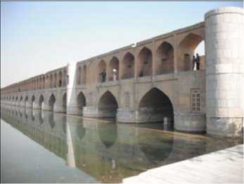
Figure 5.1. An example of cover image
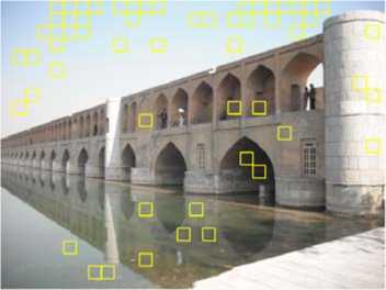
Figure 5.2. Randomly chosen blocks are shown in yellow in the cover image
type image formats could be used as input cover image to our algorithm; however its output stego-image format could not be of a lossy one; and its format out to be changed to one of the first two types, i.e. png.
III. Capacity
In the proposed algorithm, the cover images’ capacity has a direct correlation with the number and size of the selected blocks as well as the size of the “matrix patterns”. Generally, if the cover image size becomes larger, the suitable number of blocks increases without compromising the transparency of stego-image. Also capacity of each block depends on the block texture. The capacity of the block which is available for hiding the secret message, C, may be calculated as:
C = C block — C pattern
Where refers to the primary capacity of determine block in the cover image and refers to the area of the block which is available for selecting the “matrix patterns”. The total capacity of the cover image, which is the aggregation of all the selected blocks in the cover image, is:
C total = £ n _ 1 C (i)
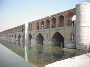
Figure 5.3. The stego-image that hides a message with 5000 characters
-
E. Implementation
The steganography algorithm developed in this project is implemented using Matlab package. The inputs to this steganography system are the secret message, an image to be used as a cover image, and the user-selected sizes for the building blocks and the “matrix patterns”. This system output is a stego-image with embedded secret message and algorithm’s parameters including used seed values, building block size, and “matrix patterns” size.
Reversely, in the extraction side, an assumed stego-image is the input to the system. The output of the decoder would be a readable secret message, if available, extracted from the stego-image.
-
F. Supported Image Formats
Image formats maybe classified as those without any compression, such as bmp, with some lossless compression, such as png, and with lossy compression, such as jpeg [12]. The first and the second file formats are completely consistent with our algorithm. The third
In (2), n is the number of selected building blocks. Size of each square block and each “matrix pattern” can be changed, but in this paper we chose a fix size for them to be able to compare it with the similar algorithm. For our simulations, we selected 10 images with PNG format out of the image database at the University of Wisconsin Madison [13]. At first, three different square block size consist of 32x32, 64x64 and 128x128 are chosen. Then longest message that its part or in its entirety could be hidden in entire images with these blocks are used. For this purpose 14 different “matrix pattern” size include; 2x1, 2x2, 3x1, 3x2, 3x3, 4x1, 4x2, 4x3, 4x4, 5x1, 5x2, 5x3, 5x4 and 5x5 are examined. Notice that the first row of each “matrix pattern” does not have any rules during embedding algorithm and set zero, so we did not select a “matrix pattern” which have more column than row.
Table IV shows the average capacity, PSNR, and resistance against “Regular singular” (RS) and “Sample Pair” (SP) attacks for all 10 images with different matrix patterns when the message is embedded in the entire images. Table V shows the average capacity, PSNR, and the resistance against RS and SP attacks for each matrix pattern size for different block size.
TABLE IV. COMPARE OF DIFFERENT BLOCK SIZE
|
32x32 |
64x64 |
128x128 |
|
|
Capacity |
15108.8 |
26615 |
30338.7 |
|
RS |
3.02 |
2.95 |
2.99 |
|
SP |
6.57 |
6.21 |
6.09 |
|
PSNR |
47.13 |
44.73 |
43.83 |
TABLE V. COMPARE THE DIFFERENT SIZE FOR “MATRIX PATTERN”
|
Capacity |
RS |
SP |
PSNR |
|
|
2x1 |
0 |
- |
- |
- |
|
2x2 |
35165.3 |
3.19 |
6.69 |
48.12 |
|
3x1 |
35353.9 |
3.24 |
6.92 |
46.76 |
|
3x2 |
34962.5 |
2.92 |
6.54 |
46.1 |
|
3x3 |
26641.5 |
2.96 |
6.29 |
46.3 |
|
4x1 |
38751.9 |
2.97 |
6.22 |
44.79 |
|
4x2 |
28998.8 |
2.87 |
5.95 |
44.43 |
|
4x3 |
19588.5 |
2.83 |
5.89 |
44.78 |
|
4x4 |
15157.1 |
2.8 |
5.83 |
44.71 |
|
5x1 |
31977.8 |
2.95 |
6.49 |
44.37 |
|
5x2 |
20989.3 |
2.96 |
6.29 |
44.25 |
|
5x3 |
13964 |
2.94 |
6.27 |
44.42 |
|
5x4 |
10768.8 |
2.93 |
6.22 |
44.36 |
|
5x5 |
8203.2 |
2.87 |
6.15 |
44.61 |
According to the Table IV, all block sizes show similar and good resistance against RS and SP attacks. However, the block size 32x32 only can provide about half of the space that others can provide for the steganography. Also all of them provide a good PSNR.
Based on Table V, we decided to choose the matrix pattern sizes that are the providing the best results including 2x2, 3x1, 3x2, 3x3, 4x1, 4x2 and 5x1. Table VI shows the results for the experiments where 2000 characters are hidden in each of 10 images that have different matrix pattern and block sizes.
TABLE VI. COMPARING DIFFERENT BLOCK SIZE WITH 2000 CHARACTERS
|
32x32 |
64x64 |
128x128 |
|
|
Capacity |
2000 |
2000 |
2000 |
|
RS |
3.68 |
3.66 |
3.66 |
|
SP |
4.6 |
7.95 |
8.09 |
|
PSNR |
57.25 |
57.33 |
57.9 |
As you can see, in Table IV, the images with block sizes of 64x64 and 128x128 have a better capacity than images with 32x32 block sizes. Although images with both block sizes, 64x64 and 128x128, have a high PSNR and good resistance against attacks, we decided to choose images with 64x64 block pixels for the further experiments in this paper because smaller blocks of size 64x64 provide more diffusion.
For choosing the best matrix pattern size, we run a new experiment and compare those patterns that show the best results provided in Table V. In this experiment, the pseudo-random generator is used for choosing some random blocks in the 10 images that their size of pixel blocks is 64x64. Then, the maximum possible message is hidden in these blocks with different sizes of matrix pattern. It can be seen in Table VII that the matrix patterns 3x1, 3x2 and 4x1 have the best capacity. However, 13 of 30 images with matrix pattern 3x1 and 1 of 3 of images with matrix pattern 4x1 cannot hide anything. On the other hand, the images with matrix pattern 3x2 are good in capacity while their failure is less. Thus, we decided to use images with matrix patterns of 3x2 for hiding the message in our experiments. Nevertheless, the user can chose any block size and “matrix pattern” size.
TABLE VII. COMPARE OF DIFFERENT “MATRIX PATTERN”
|
Capacity |
RS |
SP |
PSNR |
Fail |
|
|
2x2 |
8914.9 |
3.73 |
8.29 |
57.89 |
12/30 |
|
3x1 |
10932.8 |
3.93 |
8.76 |
55.24 |
13/30 |
|
3x2 |
10028.2 |
3.43 |
7.36 |
56.54 |
6/30 |
|
3x3 |
9053.4 |
3.15 |
5.57 |
56.21 |
5/30 |
|
4x1 |
10887.1 |
3.38 |
7.29 |
54.5 |
10/30 |
|
4x2 |
9097.8 |
3.19 |
6.75 |
54.92 |
5/30 |
|
5x1 |
9271.7 |
3.22 |
5.66 |
56.11 |
6/30 |
As it has been described above, in our algorithm the capacity of an image is not static, and it depends on the number of selected square blocks, size of square blocks, size of “matrix pattern” and texture of each block. In this paper, based on the results shown in this section, we will use blocks with fixed 64x64 sizes and fixed 3x2 for “matrix pattern”. Thus, each block can hide at most 640 characters.
-
IV. Steganalysis
Steganalysis algorithms try to find the digital covers that carry some hidden information. Two kinds of steganalysis are usually employed on image covers, signature and statistical [14]. In first type, pattern repetition signatures that are produced with steganography tools are inspected. In statistical class, the digital (image) cover is statistically analyzed to detect if the media digital carries a secret message. Statistical steganalysis is more powerful than signature steganalysis, because statistic values are more sensible than visual discernment [14, 15]. In other words, steganalysis try to determine if any information is hidden in an image by attacking the security of steganography algorithm. Some of these methods used in steganalysis include Chi-square (X2), Regular singular and Sample Pair [16, 17, 18]. In addition to these classic steganalysis methods, there are some image processing and geometric attacks that instead of identifying the existence of hidden images, try to destroy the information that may be hidden in an image by attacking the robustness of steganography algorithm. Some of these attacks include resizing, scaling, cropping, LSB filliping, JPEG compressing, adding different types of noise, et. al [3, 19].
Our algorithm does not make sensible changes in the histogram of stego-images. You can see that the histograms in Fig. 6.1 and Fig. 6.2 are the same while the Fig. 6.1 shows the histogram of the gray level in cover image shown in Fig. 5.1 and the Fig. 6.2 indicate the histogram of gray level for the stego-image shown in Fig. 5.3 produce with Matlab. The histogram of blue layer in cover image and stego-image shown in Fig. 5 are also shown in Fig. 7.1, and Fig. 7.2. By comparing the histograms in Fig. 6 and Fig. 7, you can see that they are very similar. Thus, these kinds of attacks cannot be very successful on our algorithm and our algorithm is more robust against the steganalysis attacks that get benefit from statistical or brightness changes in histogram of stego-image.
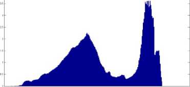
Figure 6.1. histogram of gray level for cover image
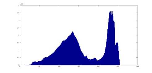
Figure 6.2. histogram of gray level for stego-image
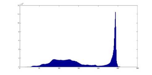
Figure 7.1. shows the histogram of blue layer for cover image

Figure 7.2. shows the histogram of blue layer in stego-image
To illustrate this, we employed RS and Sample Pair steganalysis on some stego-images that were generated by our algorithm applying Steganography_Studio1.0.1 [20]. For example, we applied these attacks, RS and Sample Pair, on the stego-image shown in Fig. 5.3 where 5000 characters are hidden in the image. The RS attack could anticipate the existence of hidden image with the probability of 0.18. It also anticipates this in the blue layer with probability of 0.08. Applying the Sample Pair attack, it could have the estimation that the image and blue layer contain hidden images with probabilities of about 0.1 and 0.02. You can see that both attacks are not effective on our algorithm at all The X2 attack detects changes in an image by comparing the number of pair of value in the histogram; because of no sensible changes in our histogram this attack cannot be successful. We implemented the X2 attack and run it on the image in Fig. 5.3. This attack assumes that different percentage of image (1%-100%) has been used for steganography and identifies the probability that actually some information is hidden in the image. The experiment shows that X2 always returns zero as the probability of hiding. Thus, it is not effective on our algorithm.
Some steganography algorithms such as PVD [21] use the differences between neighbor pixels. To attack this kind of steganography, a steganalysis method has been proposed that uses the “difference histogram” of an image [22]. We applied this attack on our algorithm. Fig. 8.1 indicates the difference histogram of the cover and Fig. 8.2 plots the difference histogram of the stego-image that is shown in Fig. 5. They illustrate that our algorithm is resistant against this technique. The reason is that our algorithm does not make any changes on the symmetric Gaussian format of the difference histogram.
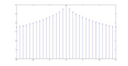
Figure 8.1. difference histogram of gray level of cover image
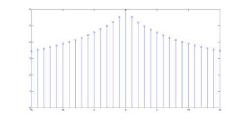
Figure 8.2. difference histogram of gray level of stego-image
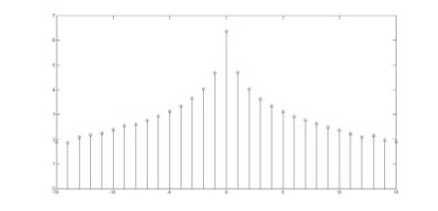
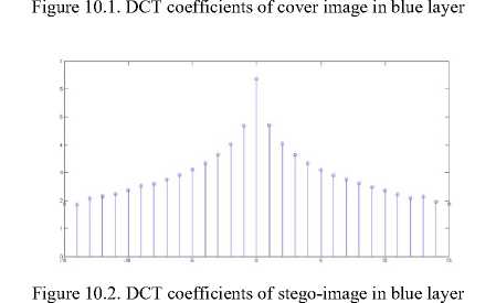
Here is another kind of steganalysis attack that is usually successful in frequency domain and it benefits from the statistical model of DCT coefficients of images [14]. It has been shown that the DCT coefficient histogram of clear image that does not contain any extra information has a symmetric and Gaussian format [23]. Fig. 9 and Fig. 10 illustrate that our algorithm does not change the Gaussian format of DCT histogram of the stego-image shown in Fig. 5. The reason is that the DCT coefficients of cover image do not change during any of the steganography steps. Therefore, these kinds of attacks are also not effective on our algorithm.
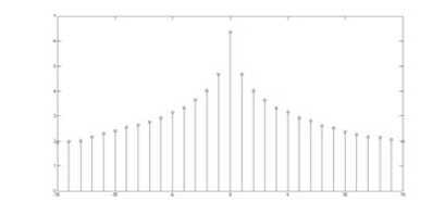
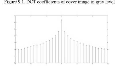
Figure 9.2. DCT coefficients of stego-image in gray level
Fridrich et al. [24] proposed another reliably steganalysis attack that can detect modifications in digital images only when the cover image is stored in the JPEG format. Since our algorithm accepts a variety of input formats for cover image, user can choose any format except JPEG for confronting this attack.
Results indicate that our algorithm is resistance against the well-known steganalysis attacks that try to identify whether an image contains any additional information. However, this algorithm similar to other steganography methods that use spatial domain is not resistance enough against image processing and geometric attacks. As it was mentioned earlier, these attacks change images without detecting the stego-image; thus, because the attackers never discover if any hidden image exists, they do not threat the security of our algorithm. Nevertheless, our method is resistance against different sorts of geometric attacks that use LSBs part of the image like LSB flipping.
-
V. Method’s Comparison
We evaluate our algorithm by comparing it with a similar algorithm described by Fatemi et. al. [11]. Before discussing the results, we briefly describe their algorithm.
In their method, sender and receiver need to share an image database with a limited number of images. Transmitting this image database is a key security problem that is assumed to be done offline. In their algorithm, for each image programmer chooses an area with a fine or uniform texture manually. Then, depending on the texture of chosen area, the programmer needs to choose some masks manually as a pattern for each character in each image. All these manually chosen images along with their masks and their selected areas are needed to be saved in the database and will be used for embedment. In the embedding step, the masks for each image are replaced with the part of area that is previously chosen.
In our algorithm however, there is no such limitation and no need for saving images, their masks or areas in a database. As a result, neither manual pre-processing nor transmitting of data is needed before running the steganography algorithm. Moreover, in our algorithm, blocks in an image are chosen randomly and for each character in each block, separate “matrix patterns” are defined automatically which all increase the security of our algorithm. Notice that in their method some masks are chosen manually for each character in an image; however our method for each block chooses some specific “matrix patterns”.
Simulation results show our method has a better transparency than their method, because of two reasons: firstly, “matrix patterns” are chosen from a difference of neighbor pixels in a block to be used only on that block, whereas in their method, they choose some masks for the whole image. Secondly blue layer of image is used in our algorithm, while in their method all the three layers are used as a mask and it is replaced in different parts of image. Moreover, performing RS and Sample Pair attacks on our algorithm by applying Steganography_Studio1.0.1, it demonstrates more resistance.
In their method, they peruse 11 images with BMP format in the database. To compare these algorithms, we used these 11 images but in PNG format which is more common in Internet. We compared their max capacity, and their transparency. We also performed several attacks including RS and Sample Pair. The comparison results are shown in Table VIII and Table X.
For calculating PSNR initially should achieve the brightness. To reach the brightness of any image, first of all green, red and blue layers of image are separated. Secondly, using (3), the brightness is calculated [25, 26]. This equation indicates that the blue layer has less effect on image brightness than other layers. Thus, to increase the transparency of the stego-image, the blue layer is used in this paper. Equation (4) can be use for comparing the brightness of cover image, and stego-image where n and m show the column size and row size of an image and “I” refers to the cover image and “S” refers to the stego-image [28].
Brightness ( P ( r , g , b )) = (0.2126* r ) + (0.7152 * g ) + (0.0722* b )
MSE = —“ ^ " = , ^ ” = 1 [ ( Brightness ( I ( i , j )) - Brightness ( S ( i , j ) ) ) ]
PSNR is a measure for transparency in an image. If it becomes more than 30, it shows that the changes in the image cannot be recognized by eye [27], and thus it has a better transparency. PSNR can be calculated with (5). In this equation, “I” refers to the cover image and “S” refers to the stego-image.
MSE is the different brightness that can be calculated using (4).
, ( 255 )
PSNR ( I , S ) = 20. log 10 , 55
( V MSE ( I , S ) J
TABLE VIII. RESULTS OF OUR ALGORITHM
|
Capacity |
RS |
SP |
PSNR |
|
|
Baboon |
33138 |
2.87 |
28.76 |
40.52 |
|
Face |
152192 |
0.37 |
0.47 |
50.08 |
|
Meadow |
140411 |
2 |
2.71 |
41.9 |
|
Paper |
17415 |
2.17 |
1.88 |
45.03 |
|
Shrine |
113318 |
2.53 |
3.68 |
44.41 |
|
Sky |
50963 |
1.61 |
1.4 |
49.18 |
|
Snow |
102493 |
0.16 |
0.27 |
50.95 |
|
Spring |
163830 |
3.53 |
3.32 |
44.68 |
|
Springhead |
120974 |
0.07 |
0.36 |
46.53 |
|
Stone |
132134 |
0.45 |
0.78 |
44.64 |
|
Wall |
96514 |
0.2 |
0.34 |
45.74 |
|
Average |
102125.6 |
1.45 |
4 |
45.79 |
TABLE X. RESULTS OF PREVIOUS ALGORITHM
|
Capacity |
RS |
SP |
PSNR |
|
|
Baboon |
119 |
4.12 |
4 |
38.29 |
|
Face |
2233 |
1.72 |
1.42 |
39.64 |
|
Meadow |
2785 |
11.36 |
13.04 |
29.48 |
|
Paper |
2293 |
5.07 |
4.28 |
51.6 |
|
Shrine |
145 |
2.52 |
3.7 |
43.16 |
|
Sky |
1066 |
2.23 |
1.77 |
25.45 |
|
Snow |
1881 |
0.71 |
0.98 |
39.74 |
|
Spring |
738 |
4.8 |
4.25 |
37.87 |
|
Springhead |
313 |
0.87 |
0.85 |
55.47 |
|
Stone |
119 |
0.63 |
0.87 |
54.38 |
|
Wall |
1640 |
0.96 |
0.77 |
32.67 |
|
Average |
1212 |
3.18 |
3.26 |
40.7 |
These tables show that our algorithm could hide 102125.6 characters in each image of this database, whereas their algorithm could only hide 1212 characters. So our algorithm can hide near 84.26 times more characters. Notice that their cover images is BMP and has near 2.5 times more image capacity, however our algorithm’s hiding capacity is 84.26 times more. In addition, Table VIII and Table X show that in the worst case, when they hide maximum information, both algorithms have a good resistance against the RS and Sample Pair attacks. However, still our algorithm shows 2.19 times more resistance to RS and a quite better transparency while their algorithm is 1.23 times more resistance to Sample Pair. Notice that our algorithm has a quite equal resistance while it hides 84.26 times more information in images with PNG format.
The simulation results indicate that both of these algorithms have a good transparency for stego-image when they hide the maximum number of characters, and both have noticeable difference from tolerable PSNR. However, for comparing the transparency of these two algorithms, we decided to hide equal characters with the maximum capacity of previous algorithm. Results are illustrated in Table XI.
TABLE XI. RESULTS OF THE PROPOSED ALGORITHM WHEN THE IMAGES ARE EMBEDDED SIMILAR TO MAX CAPACITY OF PREVIOUS ALGORITHM
|
Capacity |
RS |
SP |
PSNR |
|
|
Baboon |
119 |
3.04 |
3.56 |
61.53 |
|
Face |
2233 |
0.43 |
0.7 |
69.51 |
|
Meadow |
2785 |
4.78 |
7.32 |
67.81 |
|
Paper |
2293 |
2.86 |
2.45 |
53.13 |
|
Shrine |
145 |
2.57 |
3.73 |
81.61 |
|
Sky |
1066 |
1.78 |
1.52 |
68.17 |
|
Snow |
1881 |
0.19 |
0.35 |
69.76 |
|
Spring |
738 |
4.64 |
4.2 |
74.36 |
|
Springhead |
313 |
0.09 |
0.4 |
79.64 |
|
Stone |
119 |
0.62 |
0.96 |
79.67 |
|
Wall |
1640 |
0.18 |
0.22 |
70.24 |
|
Average |
1212 |
1.93 |
2.31 |
70.49 |
This shows that with the same number of hidden characters, our algorithm increases the PSNR 1.73 times more.
-
VI. Conclusion
In this paper, we presented a novel steganography method base on “matrix patterns” in the image spatial domain for hiding a text message on a given cover image.
In this algorithm the blue layer of RGB images are used for hiding secret message. For this purpose BxB blocks of cover image are picked randomly with a pseudo-random generator and then some t1xt2 “matrix patterns” representing 48 English characters, numerals, special characters and one “matrix pattern” to be identified as the end of secret message.
References Steganography on RGB Images Based on a “Matrix Pattern” using Random Blocks
- W. Stallings, “Cryptography and Network Security—Principles and Practices”, fourth ed., Dorling Kindersley (Pearson Education, Pvt. Ltd.), India, 2004.
- M. M. Amin, M. Salleh, S. Lbrahim and et al, “Information hiding using steganography”,Telecommunication Technology, 2003. NCTT 2003 Proceedings. 4th National Conference on. IEEE, 2003. DOI:10.1109/NCTT.2003.1188294
- A. Cheddad, J. Condell and P. Mc Kevitt, “Digital image steganography: Survey and analysis of current methods”, Signal Processing 90.3 (2010): 727-752. DOI:10.1016/j.sigpro.2009.08.010
- M. Hussain, “Pixel intensity based high capacity data embedding method”, Information and Emerging Technologies (ICIET), 2010 International Conference on. IEEE, 2010. DOI:10.1109/ICIET.2010.5625723
- S. Bhattacharyya, and G. Sanyal, “A Robust Image Steganography using DWT Difference Modulation (DWTDM)”, International Journal of Computer Network and Information Security (IJCNIS) 4.7 (2012): 27. DOI: 10.5815/ijcnis.2012.07.04
- M. Kharrazi, H. T. Sencar and N. Memon, “Image steganography: Concepts and practice”, Lecture Note Series, Institute for Mathematical Sciences, National University of Singapore (2004). DOI:10.1007/978-3-540-24624-4_3
- P. C. Su, and C. C. Kuo, “Steganography in JPEG2000 compressed images”, Consumer Electronics, IEEE Transactions on 49.4 (2003): 824-832. DOI:10.1109/TCE.2003.1261161
- E. T. Lin and J. D. Edward, “A review of data hiding in digital images”, IS AND TS PICS CONFERENCE. SOCIETY FOR IMAGING SCIENCE & TECHNOLOGY, 1999. DOI:10.1.1.29.5002
- B. Chen, and G. W. Wornell, “Quantization index modulation: A class of provably good methods for digital watermarking and information embedding”, Information Theory, IEEE Transactions on 47.4 (2001): 1423-1443. DOI:10.1109/18.923725
- A. Gutub, M. Ankeer, M. Abu-Ghalioun, A. Shaheen and et al, “Pixel indicator high capacity technique for RGB image based Steganography”, WoSPA 2008-5th IEEE International Workshop on Signal Processing and its Applications. 2008.
- A. S. Fatemi , A. R. Naghsh-Nilchi and N. Nematbakhsh, “Image Data Hiding based on Graphical Synthesis”, (in Persian), 6th Machine Vision and Image Processing Conference, 29 July 2010.
- R. H. Wiggins, H. C. Davidson, H. R. Harnsberger, J. R. Lauman and et al, “Image File Formats: Past, Present, and Future1”, Radiographics 21.3 (2001): 789-798.
- http://homepages.cae.wisc.edu/~ece533/images Last visited 2012/11/29
- A. Nissar, and A. H. Mir, “Classification of steganalysis techniques: A study”, Digital Signal Processing 20.6 (2010): 1758-1770. DOI:10.1016/j.dsp.2010.02.003.
- R. A. Lerski, K. Schad, L. R. Boyce and et al, “VIII. MR image texture analysis—An approach to tissue characterization”, Magnetic resonance imaging 11.6 (1993): 873-887. DOI:10.1016/0730-25X(93)90205-R
- A. Westfeld, and A. Pfitzmann, “Attacks on steganographic systems”, Information Hiding. Springer Berlin/Heidelberg, 2000. DOI:10.1007/10719724_5
- J. Fridrich, M. Goljan and R. Du, “Detecting LSB steganography in color, and gray-scale images”, Multimedia, IEEE 8.4 (2001): 22-28. DOI:10.1109/93.959097
- S. Dumitrescu, X. Wu and Z. Wang, “Detection of LSB steganography via sample pair analysis”, Information Hiding. Springer Berlin/Heidelberg, 2003. DOI:10.1007/3-540-36415-3_23
- V. Licks and R. Jordan, “Geometric attacks on image watermarking systems”, Multimedia, IEEE 12.3 (2005): 68-78. DOI:10.1109/MMUL.2005.46
- http://sourceforge.net/projects/stegstudio/files/ Last visited 2012/4/7
- X. Zhang and S. Wang, “Vulnerability of pixel-value differencing steganography to histogram analysis and modification for enhanced security”, Pattern Recognition Letters 25.3 (2004): 331-339. DOI:10.1016/j.patrec.2003.10.014
- V. Sabeti, S. Samavi, M. Mahdavi and et al, “Steganalysis of pixel-value differencing steganographic method”, Communications, Computers and Signal Processing, 2007. PacRim 2007. IEEE Pacific Rim Conference on. IEEE, 2007. DOI:10.1109/PACRIM.2007.4313232
- T. Zhang and X. Ping, “A fast and effective steganalytic technique against JSteg-like algorithms”, Symposium on Applied Computing: Proceedings of the 2003 ACM symposium on Applied computing. Vol. 9. No. 12. 2003. DOI:10.1145/952532.952595
- J. Fridrich, M. Goljan and R. Du, “Steganalysis based on JPEG compatibility”, ITCom 2001: International Symposium on the Convergence of IT and Communications. International Society for Optics and Photonics, 2001. DOI:10.1117/12.448213
- I. Jackson and S. Sirois, “Infant cognition: going full factorial with pupil dilation”, Developmental science 12.4 (2009): 670-679. DOI:10.1111/j.1467-7687.2008.00805.x
- T. S. Sazzad, M. Z. Hasan and F. Mohammed, “Gamma encoding on image processing considering human visualization, analysis and comparison”, International Journal 4 (2012).
- J. Lee, S. Choe and S. Lee, “Compression of 3D Mesh Geometry and Vertex Attributes for Mobile Graphics”, Journal of Computing Science and Engineering 4.3 (2010): 207-224.
- P. Nithyanandam, T, Ravichandran, N. M. Santron and et al, “A Spatial Domain Image Steganography Technique Based on Matrix Embedding and Huffman Encoding”, International Journal of Computer Science and Security (IJCSS) 5.5 (2011): 456.
