Stereo rectification of calibrated image pairs based on geometric transformation

Author: Huihuang Su, Bingwei He
Journal: International Journal of Modern Education and Computer Science (IJMECS) @ijmecs
Article in issue: 4 vol.3, 2011.
Free access
The objective of stereo rectification is to make the corresponding epipolar lines of image pairs be parallel to the horizontal direction, so that the efficiency of stereo matching is improved as the corresponding points stay in the same horizontal lines of both images. In this paper,a simple and convenient rectification method of calibrated image pairs based on geometric transformation is proposed, which can avoid the complicated calculation of many previous algorithms such as based on epipolar lines, based on fundamental matrix or directly depend on corresponding points. This method is divided into two steps including coordinate system transformation and re-projection of image points. Firstly, we establish two virtual cameras with parallel optical axis by coordinate system transformation based on the pose relationship of the two cameras from calibration result. Secondly, we re-project the points of the original image onto new image planes of the virtual cameras through geometrical method, and then realized the stereo rectification. Experiments of real stereo image pairs show that the proposed method is able to realize the rectification of stereo image pairs accurately and efficiently.
Stereo rectification, coordinate transformation, calibrated cameras, epipolar lin
Short address: https://sciup.org/15010237
IDR: 15010237
Text of the scientific article Stereo rectification of calibrated image pairs based on geometric transformation
Published Online July 2011 in MECS
Stereo matching is an important part of stereo vision, the purpose of which is that searching the corresponding feature points of stereo image pairs taken from two different views of a same scene by cameras. Since there are epipolar geometry constraints in stereo image pairs, the corresponding points’ matching is implemented along the corresponding epipolar lines. While the corresponding epipolar lines of stereo image pairs lay on the same horizontal or vertical lines, the searching space will be reduced from 2-dimension to 1-dimension. And then the complex computation of epipolar line from lots of corresponding points can be avoided, that improves the searching efficiency greatly. However, it is very difficult to ensure the epipolar lines lay on the same horizontal or vertical lines in practical application, so the stereo rectification is used to transform the corresponding epipolar lines of stereo image pairs to be that style.
Ayache[1] combined the projective matrix taken from camera’s calibration result with the condition that the corresponding epipolar lines should be in the same vertical coordinates after rectification to derive the required transformation matrix. But this method made the computation large and it requires the computation of epipolar lines in derivation Fusiello [2] improved the above algorithm to be more simple and effective, although it avoided the computation of epipolar lines, but it needed two vector cross multiplications, which increased the complexity. Hartley [3] determined the projective matrix through the constraint that the vertical difference between the corresponding points should be minimized and the epipole should be at infinity. This method didn’t need to calibrate the cameras, but it was complex as several corresponding points were required to be previous known and many variables were needed to be resolved. Min Z et al [4] improved Hartley’s algorithm by the relation between epipolar line and projective transformation, it reduced the number of variables through the features of epipolar geometry. However, since the computation of epipolar lines was inevitable, the algorithm was complex. Loop et al [5] divided rectification transformation matrix into a projective and affine component, and reduced the projective distortion which come from the process of rectification through affine transformation. But it required that all involving matrix must be positive in the rectify process, and would be disturbed easily by noise. Sui Liansheng et al [6] used projective transformation to make all corresponding epipolar lines parallel to each other, and then moved the corresponding epipolar lines to the corresponding horizontal lines by offset-value which was obtained from the optimization of minimizing the vertical difference. Although the positive of matrix was not required, the complex computation of the epipolar lines was inevitable yet. John M et al [7] computed the projective transformation through fundamental matrix, and proposed a method of reducing the projective distortion by optimizing each transformation. But it also required the computation of the epipolar lines. Isgro and Trucco [8]
proposed a method that the transformation matrix could be gained directly from the corresponding points without computing the fundamental matrix, but the corresponding points should be previous known while computing the rectification transformation matrix. Similarly, Zahrani et al [9] computed the projective matrix of rectification directly from arbitrary three groups of corresponding points in stereo image pairs, but the projective distortion depended on the selection of three groups of corresponding points, so the robustness of this method was low. Lin Guoyu et al [10] proposed an algorithm based on Hartley’s and Francesco’s, for making the rectification be more robust, the transformation matrix was calculated by the corresponding points and then was optimized by Levenberg-Marquardt method and Evolutionary Programming algorithm. Dingrui Wan et al [11] proposed an epipolar line rectification algorithm based on spherical rectification for PTZ (Pan-Tilt-Zoom) cameras. This algorithm was simple and effective, but it’s limited to PTZ cameras. As well S.Kumar [12] proposed an approach for rectifying the stereo image pairs which had different zoom and image resolution, it could be applied to the vision systems composed by the cameras of different specifications, but it needed to shrink the image and fit the zoom, and also needed to calculate the epipolar lines, so the computation was still complex.
Generally, the above methods of stereo rectification have two classifications: base on fundamental matrix and not base on fundamental matrix. The former combines the epipolar lines constraint with fundamental matrix to compute the rectification matrix. And the latter computes the matrix directly from the previous known corresponding points of stereo image pairs. However, both of them require mass and complex computations.
Recently, rectification algorithms are inclined to the stereo rectification based on uncalibrated cameras, compare with the methods based on calibrated cameras, they could save the process of resolving cameras’ intrinsic and extrinsic parameters, but most of which generally required a set of previous known corresponding points, Moreover, in the applications of stereo vision, especially in 3D reconstruction with the disparities, the intrinsic and extrinsic parameters of cameras generally should be obtained in advance. Hence, this paper proposes a novel rectification algorithm of calibrated image pairs based on geometric transformation. This algorithm establishes two virtual cameras which parallel to baseline and stay at the same height by coordinate system transformation, and then reprojects the corresponding points of the original image pairs to the virtual cameras’ image plane to finish the stereo rectification. The advantage of this algorithm is as follows: a) Avoiding the complex computation of epipolar lines or the matching process of mass previous known corresponding points, simplifying the rectification. b) Realizing the stereo rectification by coordinate system transformation, simple and easy to understand. c) The intrinsic parameters of two cameras aren’t required the same.
The remaining parts of this paper are organized as follows. In section 2, preliminaries of the rectification process are given. Section 3 is devoted to introduce our algorithm in two steps. In section 4, experiments and results are presented. The conclusion of this paper is given in section 5.
-
II. Preliminaries
-
A. Camera model
Pinhole model is a common camera model (Fig.1), the image position of an arbitrary point in 3D world is approximately described by pinhole model. Let the world point be P w ( x, y, z ) and image point be p p ( u, v ), the image point p p in the image coordinate system p I ( x I , y I ) and in the camera coordinate system p c ( x c , y c , z c ) is obtained according to geometry.
x I = ( u - u 0 )k u
У 1 = ( v - v 0 )k v
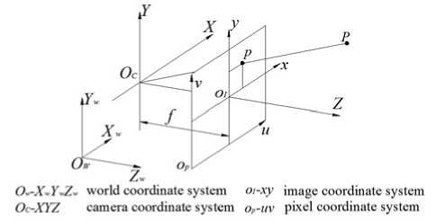
Figure 1. Pinhole Model
[ x c = f ■ ( u - u o )/ f u 1 У с = f ■ ( v - v 0 )/ f v [ z c = f
Where f is physical focal length of camera, ku and kv are the scale factors of the u and v axes, fu and fv are the product values of f and k u , k v , ( u 0 , v 0 ) is the coordinates of the principal point.
Since the cameras have been calibrated before rectification in stereo vision system, the pose between two cameras and the intrinsic parameters with each camera are previous known. And the required results in this paper are the pose of right camera relative to left and the intrinsic parameters within each camera.
|
L F R |
= [ LRr |
LT R ] |
(3) |
|
|
" f u. |
0 |
u 0 1 |
||
|
K L = |
0 |
f vl |
v 0 l |
(4) |
|
o |
0 |
1 |
||
K R
|
f ur |
0 |
u 0 r |
|
0 |
f vr |
v 0 r |
|
0 |
0 |
1 |
-
B. The configuration of stereo vision system
According to the position of two cameras’ optical axes, the configuration of stereo vision system is divided into three types: parallel-type, convergent-type and general-type (Fig.2). In parallel-type, the optical axes of two cameras should be parallel to each other and the intrinsic parameters are the same. Convergent-type requires that the optical axes of two cameras should intersect in finite distance. General-type is unconstrained. But to obtain larger field of view, both cameras are generally placed at the same height as possible and the angle is set a certain value. In practical it’s very difficult to make the optical axes parallel or convergent, so the common configuration of stereo vision system is general-type.
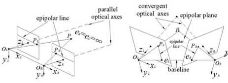
a) parallel-type
b) convergent-type
c) general-type
Figure 2. The configuration of stereo vision system
In Fig.2, the optical centers of two cameras ( O L , O R ) and the world point P constitute the epipolar plane. The intersection of the epipolar plane and the camera’s image plane is called epipolar line. Baseline is the line OLOR between the cameras’ optical centers, and its intersection with the image plane is defined as epipole. When the projective point in one image plane of a world point is given, its corresponding point on the other image plane is found along the corresponding epipolar line, which called epipolar geometry constraint.
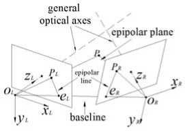
Since the epipolar lines are not collinear in the general-type and convergent-type of stereo vision system (Fig.2b and Fig.2c), it needs substantial computation while using epipolar lines to search corresponding points. However, in the parallel-type the corresponding epipolar lines stay at the same height (Fig.2a) and the optical axes are parallel to each other, so that the corresponding points is directly searched along the horizontal direction. To ensure the matching efficiency in convergent-type and general-type consistent with the parallel-type, we need to transform these two types into virtual parallel-type (Fig.3), which is called stereo rectification.
р
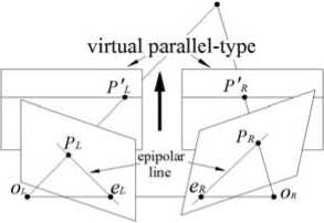
Figure 3. The schematic of stereo rectification
-
III. The rectification of stereo image pairs
The algorithm in this paper consists of two steps. In the first step, according to the position relation between two cameras which have been obtained from calibration, the original image points are converted to the coordinate system of the virtual parallel-type through coordinate transformation. In the second step, the image points which have been transformed to new coordinate system are mapped to the image plane of the virtual parallel-type by re-projecting.
-
A. The transformation of camera coordinate systems
As we know the x axes of the two cameras coordinate systems coincide with baseline and toward to the same direction in parallel-type (Fig.2a), therefore the first step of stereo rectification is to compute the transformation matrix which transforms the two cameras coordinate systems to parallel-type.
Assume left camera coordinate system is L ( O L -x L y L z L ), the baseline is O L O R . And the objective is to obtain the transformation matrix of transforming the coordinate system L ( O L -x L y L z L ) to the new coordinate system L′ ( O L -x′ L y′ L z′ L ) whose x axis coincides with the baseline O L O R . First let the world coordinate system coincide with the coordinate system L and the coordinate of point O R in the world coordinate system is O R ( t 1 , t 2 , t 3 ) which have been gained from LT R . And then according to geometry, the conversion from the left camera coordinate system L to new coordinate system L′ is realized through rotating α around y axis of the world coordinate system and then rotating β around z axis of the world coordinate system (Fig. 4).
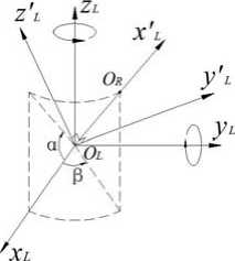
Figure 4. Transformation of the coordinate system
Then according to S. B. Niku [13], the transformation matrix of the coordinate system L′ relative to the coordinate system L is obtained:
L Fu = R ( z , в ) ■ R ( y , a ) (6)
Where:
|
R ( y , a ) = |
cos a 0 |
0 sin a 10 |
(7) |
|
- sin a cos в |
0 cos a - sin в 0 |
" |
|
|
R ( z , в ) = |
sin в 0 |
cos в 0 (8) 0 1 |
|
α and β is estimated by the coordinate of point O R :
sin a =
t 3
V t 12 + t 2 2 + t 3
sin в =
t 2
V 1 1 2 + 1 2 2
In practice, the destination is to get the coordinate of a point after being transformed from the coordinate system L to the coordinate system L′ (Fig. 3), so the required transformation matrix is about the coordinate system L relative to the coordinate system L′ . According to (6), the transformation matrix is obtained:
L ' Fl = L F - 1 = R - 1( y , a ) ■ R - 1( z , в )
|
cos a ■ cos в |
cos a ■ sin в |
- sin a |
|
- sin в |
cos в |
0 |
|
sin a ■ cos в |
sin a ■ sin в |
cos a |
Since cameras have been calibrated, the rotation transformation of right camera relative to left camera LR R is already known. Then the transformation matrix of right camera coordinate system is calculated with (11).
R it it -р F R = F L R R
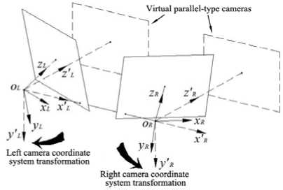
Figure 5. The schematic of the coordinate systems transformation
image information in them. To solve this problem, re-projection is implemented here. For projecting the original image points to the new image plane, the coordinates of those points in each old camera coordinate system should be previously estimated. Assume there is a left image point P pl ( u l , v l ), and then the coordinate of it in old left camera coordinate system P cL ( x cl , y cl , z cl ) is obtained with (2).
xd = f(U l - U 0 1 )/ f ull Ус! = fl ( v I - v 0 l )/ fvl Zd = fl
Now the coordinate of the image point in new left camera coordinate system P′ cL ( x′ cl , y′ cl , z′ cl ) is obtained through the transformation matrix which has been obtained.
P d- = L' Fl ■ P cL (14)
As the same, a right image point in old right camera coordinate system is P cR ( x cr , y cr , z cr ), and its coordinate in new right camera coordinate system P′ cR ( x′ cR , y′ cR , z′ cR ) is obtained.
x cr = f r ( U r y cr = f r ( v r z cr = L
- И 0 r )/ f ur - v 0 r )/ f>„
P' = R> . p cR R cR
After getting the coordinates of the image points in new coordinate system, we need to re-project them to the image plane of virtual camera to complete the rectification. As it shows in Fig.6, P pl ( u l , v l ) is an image point of the original left camera, and the coordinate of it in the new left camera coordinate system P′ cL ( x′ cl , y′ cl , z′ cl ) is obtained after the above-mentioned method. Let the focal length of cameras be f n and the principal point be ( u′ 0 , v′ 0 ) in parallel-type system, then the projection point of P pl in the image plane of left virtual camera P′ pl is the intersection of line O L P′ cL and plane z = f n . According to mathematics, the equation of the line OLP′cL is as follow.
xyz x'cl y cl z'c l
And the intersection point P′nL(x′nl, y′nl, z′nl) is x’l = f ■ x'cjz’t nl n cl cl y'nl = fn ■ y'<^llz'd z nl = fn
Projecting the point P′ nL ( x′ nl , y′ nl , z′ nl ) to the image plane of left virtual camera is executed with (1), and the coordinate of it in pixel coordinate system P′ pl ( u′ l , v′ l ) is as follow.
u = k nu ■ x nl + И 0 1 = f nu ■ x'd/z'd + И 0
. v c = k nv ■ y ^l + v 0 1 = f„. ■ y' d I c'd + v 0
In right original image, the corresponding image point of Ppl ( ul, vl ) is Ppr ( ur, vr ), and its coordinate in right camera coordinate system is P′cR ( x′cr, y′cr, z′cr ) which have been obtained in (16). The same with left re-projection, the projection point of P pr in the image plane of right virtual camera P′ pr is the intersection of line O R P′ cR and plane z = f n . the equation of the line O R P′ cR is as follow.
xyz x' y' z'
cr cr cr
And the intersection point P′nR(x′nr, y′nr, z′nr) is xnr = fn ■ x‘rKr y nr fn ycr /' zcr z ’ = f nr n
Then the coordinate of P pr ( u r, v r ) is obtained from (1), the result is as follow.
| U = f nu ■ x C rK r + u 0
1 v r = fnv ■ y Cr/ z Cr + v 0
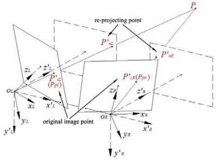
Figure 6. The schematic of left camera’s re-projection
After re-projection, the original image information is transfer to the virtual parallel-type cameras’ image plane, and then stereo matching is implemented rapidly as the rectification is finished.
-
IV. Experiments
The proposed algorithm is tested with image pairs taken by a stereo vision system which is composed of two AVT Marlin F-080C cameras with 1024×768 resolution. The pose relationship of these two cameras is unknown, also the focal length and principal points of them is uncertain, so the extrinsic and intrinsic parameters of this stereo vision system are calculated using the calibration method which proposed by zhengyou Zhang[14] before rectification, and then the proposed algorithm is implemented after distortion correction.
Table 1 shows the intrinsic and extrinsic parameters of cameras which obtained from calibration. From LT R we can get α and β.
a = arcsin ^^ .75 = 9.693 ° (22)
V378.772 + 15.512 + 64.752
в = arcsin 15.51 ----- = 2.345 ° (23)
V378.772 + 15.512
TABLE I. The intrinsic and extrinsic parameters of
CAMERAS
|
left camera |
right camera |
|
|
f u |
3472.60 |
3466.08 |
|
f |
3470.35 |
3465.03 |
|
intrinsic |
0 |
0 |
|
s parameters u 0 |
583.95 |
633.76 |
|
v 0 |
447.05 |
514.444 |
|
" 0.9443 |
0.0285 -0.3279 " |
|
|
L R R = -0.0270 |
0.9996 0.0093 |
|
|
extrinsic parameters |
0.3280 |
0 0.9447 |
|
L T R = [ 378.77 |
15.51 64.75 ] T |
Then according to (11) and (12), the transformation matrixes of cameras are computed, and then the virtual parallel-type system is able to set up.
|
L F L = |
0.9849 -0.0409 -0.1682 |
0.0403 0.9991 -0.0069 |
0.1684 " 0 0.9857 |
(24) |
|
Г |
0.9842 |
0.0684 |
-0.1635 " |
|
|
RF = F R |
-0.0655 |
0.9976 |
0.0227 |
(25) |
|
[ |
0.1647 |
-0.0116 |
0.9863 |
As the intrinsic parameters of cameras are required to be identical in parallel-type stereo system, we make both cameras’ intrinsic parameters are equal to left camera’s in parallel-type stereo system, as table 2 shows. Then we re-project image points using these parameters to realize the rectification.
TABLE II. The intrinsic parameters of parallel-type
STEREO SYSTEM
|
f nu |
f nv |
s′ |
u′ 0 |
v′ 0 |
|
|
left virtual camera |
3472.60 |
3470.35 |
0 |
583.95 |
447.05 |
|
right virtual camera |
3472.60 |
3470.35 |
0 |
583.95 |
447.05 |
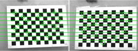
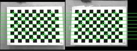
For verifying our rectification algorithm’s feasibility and effectiveness, experiments have been divided into two parts. The first part of experiments is implemented on chess board which has been used to calibration. A pair of chess board images before and after rectification is presented in Fig. 7, and table 3 shows that the vertical coordinates and the vertical disparities of the corners marked in the images. From the chart it can be seen that the corresponding corners don’t lay on a same horizontal lines before rectification, but the vertical disparities of them almost equal to zero after rectification, so the proposed algorithm is feasible.
a) Before rectification
TABLE III. The Vertical Disparities of Corresponding
Corners Before And After Rectification
b) After rectification
Figure 7. Pair of chess board images before and after rectification
|
The vertical coordinate before rectification(pixels) |
The vertical coordinate after rectification(pixels) |
||||
|
Left image |
Right image |
Vertical disparity |
Left image |
Right image |
Vertical disparity |
|
193.701 |
218.365 |
-24.664 |
186.376 |
186.449 |
-0.073 |
|
184.647 |
184.647 |
-26.540 |
183.908 |
184.003 |
-0.095 |
|
251.931 |
276.836 |
-24.905 |
246.551 |
246.577 |
-0.026 |
|
247.569 |
274.702 |
-27.133 |
245.656 |
245.662 |
-0.006 |
|
311.045 |
336.991 |
-25.946 |
307.345 |
307.302 |
0.043 |
|
301.224 |
334.224 |
-33.000 |
305.947 |
305.912 |
0.035 |
|
374.354 |
398.336 |
-23.982 |
368.868 |
368.866 |
0.002 |
|
365.674 |
397.281 |
-31.607 |
367.878 |
367.975 |
-0.097 |
|
437.04 |
459.207 |
-22.1672 |
430.432 |
430.398 |
0.034 |
|
421.139 |
459.230 |
-38.091 |
429.355 |
429.288 |
0.067 |
|
493.130 |
520.632 |
-27.502 |
491.899 |
491.858 |
0.041 |
|
544.617 |
584.41 |
-39.794 |
553.727 |
553.802 |
-0.075 |
|
611.569 |
645.644 |
-34.075 |
616.310 |
616.234 |
0.076 |
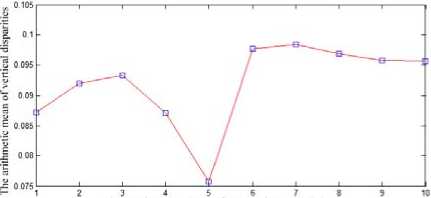
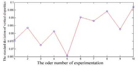
In order to verify the proposed algorithm more effectively, we have ten pairs of chess board images to experiment, and calculate the arithmetic mean value and standard deviation value of all corresponding corners’ vertical disparities after rectification (Fig. 8). From the chart it can be seen that the arithmetic mean value and standard deviation value are less than 0.1 pixels. This indicates that our algorithm can effectively realize the stereo rectification.
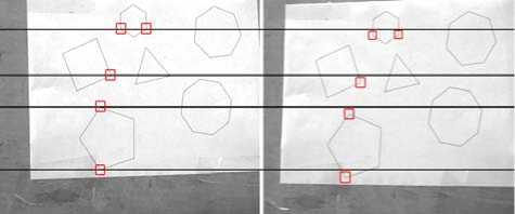
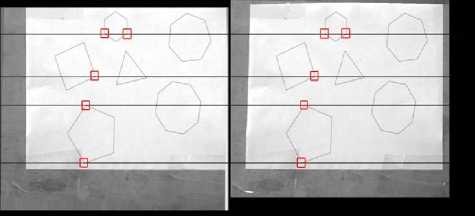
The second part of experiments is carried out by several image pairs of real scene to verify the practicability of our algorithm. Fig. 9 is the image pairs of a board on which a paper with the principal geometric shapes is pasted. Before rectification, the corresponding corners do not stay along the same horizontal lines. And after rectification, all corresponding corners are transferred to the corresponding horizontal lines. From this result, the algorithm in our paper is practical.
The order number of experimentation
a) Before rectification
a) The arithmetic mean of vertical disparities
b) The standard deviation of vertical disparities
Figure 8. The statistical results of experiments
b) After rectification
Figure 9. A board with principal geometric shapes
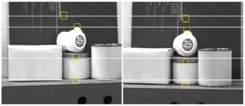
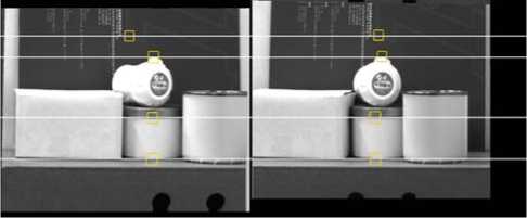
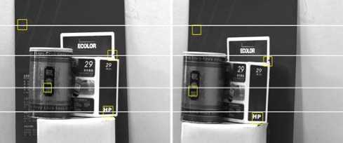
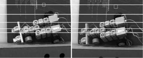
Fig.10, 11 and 12 show the comparison diagrams of before and after rectification of the real scene images which taken by the stereo vision system with different pose relationship between the two cameras. Before rectification, the corresponding features of both images which marked in figures lie in different horizontal lines, as Fig.10a, 11a and 12a show. But after rectification, the corresponding features lie in the corresponding horizontal lines in Fig.10b, 11b and 12b. From these experimental results, the rectification algorithm in this paper is available for real scene images, and also effective for different configuration of stereo system.
a) Before rectification
b) After rectification
Figure 10. Rectification of one real scene image pairs
a) Before rectification
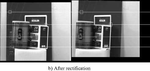
Figure 11. Rectification of another real scene image pairs
a) Before rectification
Figure 12. Rectification of the third real scene image pairs
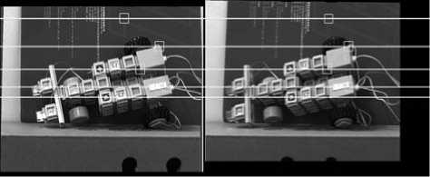
b) After rectification
-
V. Conclusions
An algorithm of stereo rectification based on calibrated cameras with coordinate system transformation is presented in the paper. After getting the intrinsic and extrinsic parameters of cameras from calibration, we can combine the invariance of cameras’ optical centers with coordinate system transformation to establish a virtual parallel-type stereo vision system at first, and then re-project all the original image points of left and right cameras to the new image plane of each virtual camera by geometry, finally finish the whole process of the rectification. This algorithm avoids the complex computation of epipolar lines or fundamental matrix, also omit the matching process of large corresponding points in uncalibrated cameras’ rectification, and it is more simple and intuitive than previous algorithm. At last, various experiments have been carried out and the results show the proposed algorithm is effective and feasible.
Acknowledgement
The work described in this paper was supported in part by a grant from Program for New Century Excellent Talents in Fujian Province University (Project no. XSJRC2007-07).
References Stereo rectification of calibrated image pairs based on geometric transformation
- N Ayache, C Hansen, “Rectification of image for binocular and trinocular stereovision,” In proceedings of 9th International Conference on Pattern Recognition, pp.11-16, 1988.
- A Fusiello, E Trucco, A Verri, “A compact algorithm for rectification of stereo pairs,” Machine Vision and Applications, vol. 12, pp.16–22, July 2000.
- R Hartley. “Theory and practice of projective rectification,” International Journal of Computer Vision, vol. 35, NO.2, pp.115–127, Nov 1999.
- M Zhu, Y Ge, S Huang, W Chen, “Stereo vision rectification based on epipolar lines match and three variables projective matrix,” In Proceedings of the 2007 IEEE International Conference on Intergration Technology, pp.133-138, 2007.
- Charles Loop, Zhengyou Zhang, “Computing rectifying homographies for stereo vision,” In Proceedings of IEEE Computer Society Conference on Computer Vision and Pattern Recognition, vol. 1, pp.125-131, 1999.
- Sui Liansheng, Zhang Jiulong, Cui Duwu, “Image rectification using affine epipolar geometric constraint,” In Proceedings of International Symposium on Computer Science and Computational Technology, vol.2, pp.582-588, 2008.
- John Mallon, Paul F. Whelan, “Projective rectification from the fundamental matrix,” Image and Vision Computing, vol. 23, pp.643–650, July 2005.
- F. Isgro, E. Trucco, “Projective rectification without epipolar geometry,” In Proceedings of IEEE Computer Society Conference on Computer Vision and Pattern Recognition, pp.94-99, 1999.
- A Al-Zahrani, S.S Ipson, J.G.B Haigh, “Applications of a direct algorithm for the rectification of uncalibrated images,” Information Sciences, vol. 160 NO.1-4, pp.53-71, March 2004.
- Guo-Yu Lin, Xu Chen, Wei-Gong Zhang, “A Robust Epipolar Rectification Method of Stereo Pairs,” In 2010 International Conference on Measuring Technology and Mechatronics Automation, vol. 1, pp.322-326, 2010.
- Dingrui Wan, Jie Zhou, “Self-calibration of spherical rectification for a PTZ-stereo system,” Image and Vision Computing, vol. 28, NO.3, pp.367-375, March 2010.
- S Kumar, C Micheloni, C Piciarelli, GL Foresti, “Stereo rectification of uncalibrated and heterogeneous images,” Pattern Recognition Letters, vol. 31, NO.11, pp.1445-1452, August 2010.
- Saeed B. Niku, Introduction to Robotics Analysis, Systems, Applications, Upper Saddle River, N.J., Prentice Hall, 2001.
- Zhengyou Zhang, “Flexible camera calibration by viewing a plane from unknown orientations,” In Proceedings of the International Conference on Computer Vision, vol. 1, pp.666-673, 1999.
