Stress analysis of solar array driver mechanism actuator of the spacecraft “Luna-Resurs-1”

Author: Tambasova E.V., Tokarev A.V., Pavelko S.V., Таmbаsоv I.А.
Journal: Сибирский аэрокосмический журнал @vestnik-sibsau
Section: Авиационная и ракетно-космическая техника
Article in issue: 4 т.18, 2017.
Free access
The intrrest of spacefaring nations in the Moon has grown considerably in recent years. Russia, China, the European Space Agency, the USA and some other countries have the Lunar programs. The movement around the Moon has a number of the features caused by gravitational field of the Moon, mascons and the small period of rotation. Therefore these features need to be considerd at the design of both the space vehicle and its components. The electro- mechanical block of solar array drive mechanism (SADM) of the spacecraft “Luna-Resurs-1” for a remote research of the Moon is presented. It serves for rotation of solar batteries panels and provides orientation of the panels by active part to the Sun. The purpose of this work is the analysis of strength characteristics of the spacecraft electromechanical block of SADM in the research of the Moon. Stress analysis of the basic power elements of the design by method of final elements in the Static analysis application of a CATIA package is made. The results of the calculation confirm the lifting power of a load-carrying structure. The minimum margin of safety of the most loaded detail is equal to 1.91. The developed device considers all the features of the movement on an orbit of the Moon and can be used in the research spacecrafts when studying a terrain and structure of the Lunar surface.
Stress analysis, moon exploration, solar panels, mechanical devices, satellite "luna-resurs-1"
Short address: https://sciup.org/148177774
IDR: 148177774 | UDC: 629.785
Расчет на прочность электромеханического блока устройства поворота батарей солнечных космического аппарата "Луна-Ресурс-1"
Интерес космических держав к Луне в последние годы значительно вырос. Россия, Китай, европейские государства, США и ряд других стран имеют свои лунные программы. Движение вокруг Луны имеет ряд осо- бенностей, вызванных гравитационным полем Луны, масконами и малым периодом вращения. Поэтому при проектировании космического аппарата (КА) в целом и его составных частей данные особенности необходи- мо учитывать. Представлен электромеханический блок (ЭМБ) устройства поворота батарей солнечных (УПБС) космического аппарата «Луна-Ресурс-1» для дистанционного исследования Луны. Он служит для вра- щения панелей батарей солнечных, обеспечивая ориентацию панелей активной стороной на Солнце. Целью статьи является анализ прочностных характеристик ЭМБ УПБС космического аппарата по исследованию Луны. Конструкция блока была оптимизирована. Произведен прочностной расчет основных силовых элемен- тов конструкции методом конечных элементов в приложении Static Analysis пакета CATIA. Результаты рас- чета подтверждают несущую способность силовой конструкции. Минимальный запас прочности наиболее нагруженной детали равен 1.91. Разработанный электромеханический блок устройства поворота батарей солнечных учитывает все особенности движения по орбите Луны и может применяться на научно- исследовательских КА по изучению рельефа и состава лунной поверхности.
Text of the scientific article Stress analysis of solar array driver mechanism actuator of the spacecraft “Luna-Resurs-1”
Introduction. The leading spacefaring nations of the world, such as Russia, the United States, China, Japan, India, as well as the European Space Agency (ESA) are interested in the Moon. The interest concerns the analysis of the mineralogical composition of the moon, the extraction of expensive rare earth elements and isotopes, such as gallium and helium-3 [1; 2]. A number of programs have already been implemented, and some are only being planned for implementation. So in 2003 ESA launched SMART-1, which carried out the tasks of exploring and detecting potential lunar resources, solving problems related to the theories of the origin of the Moon, and analyzing the composition of the Moon’s surface [3; 4]. In 2007 the Japanese satellite SELENE, which dealt with the origin of the Moon and studied the mineralogical composition of its surface, was launched [5; 6]. The Indian satellite Chandrayaan-1 [7; 8], the Chinese - Chang’e 1,2,3 were engaged in the solution of the problems mentioned above, in addition, in the next few years it is planned to launch spacecrafts Chang’e 5,6, providing the possibility of sampling and delivery of lunar soil to the Earth [9].
The space program approved by Roskosmos for 2016– 2025 includes the project “Moon-Globe”, which implies the use of the spacecraft “Luna-Resurs-1” intended for remote exploration of the Moon [10]. The device will solve the following tasks: mapping the mineralogical composition of the Moon, mapping the distribution of water ice on the lunar surface, studying the structure of the subsurface layers, and topography of the lunar surface. The working orbit is a circular polar lunar orbit with an altitude of 150 km and an altitude of about 100 km. The launch date is 2020 [11].
Orbital movement around the moon has a number of specific features. The force of the gravitational field of the Moon exceeds the Earth’s gravity by 5–6 times [12]. In addition, the gravitational field of the moon contains many anomalies caused by the mascons [13; 14]. The Mascon is a region of the Moon’s lithosphere, consisting of a significant mass accumulation. Therefore, when designing the spacecraft “Luna-Resurs-1” and its components, it is necessary to take into account the particular features of the motion along the Moon’s orbit. In addition, launching a spacecraft into the Moon’s orbit is much more expensive than launching a spacecraft into Earth’s orbit, so the mass of composite units and spacecraft devices should be minimal.
The description of the electromechanical block of the solar array drive mechanism (EMB of SADM). EMB of SADM is a device designed to solve the following problems [15]:
-
- rotation of solar arrays for the purpose of their orientation to the Sun;
-
- for transit transmission of electricity from solar array drive mechanism to spacecraft;
-
- giving information on the position of the output shaft of EMB of SADM;
-
- transit transmission of control signals to the drive for expanding the solar array (SA) panels.
EMB of SADM of the spacecraft “Luna-Resurs-1” (fig. 1) consists of a drive, angular position sensors, a power collector device, a telemetric current collector device.
One of the main conditions for maintaining the efficiency of EMB of SADM is its mechanical strength. At the initial stages EMB of SADM design, the estimation of the bearing capacity is carried out by numerical simulation methods, which results in decisions on structural modification, if necessary.
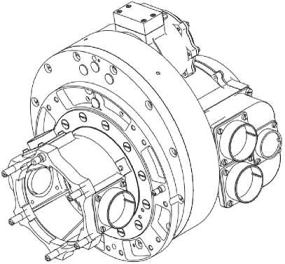
Fig. 1. Physical configuration of EMB of SADM
Рис. 1. Внешний вид ЭМБ УПБС
Static stress analysis of the main power elements of EMB of SADM. Loads acting on the electromechanical block of SADM, perceive the main load carrying elements of the structure (fig. 2).
An output flange was added into the power circuit of EMB of SADM of the spacecraft “Luna-Resurs-1”. This is done to increase the load-bearing capacity of the EMB and to distribute the mechanical stresses more evenly. The design of the EMB of SADM elements for the output flange, the output shaft, the board and the case was elaborated in detail. The optimal geometric dimensions of the stiffeners and wall thicknesses were chosen in such a way that the bearing capacity was maximum and the mass minimal. Thus, the stiffeners were added to the construction of the “Output Flange” component.
The EMB must satisfy the strength conditions and remain operative after exposure to loads aroused in the insertion phase and in the area where the solar arrays are deployed into the working position (orientation to the sun). Therefore, three simulation cases were considered. Case № 1 simulates static loads that occur during the stage of the launch of Luna-Resurs-1 spacecraft into the Moon’s orbit, when the solar cells are in a fold position. Simulation cases № 2 and № 3 imitate the loads that occur when the solar arrays are deployed into the working position (orientation to the Sun).
Fig. 3 shows the scheme for fixing the EMB of SADM. The load that occurs when the solar arrays are deployed is transferred from the output flange to the shaft. Then the force is transferred from the drive shaft through the bearing part to the board, which is attached directly to the spacecraft. The case, the cover, the flange are in the structural diagram additional elements that increase the rigidity.
The output flange, case, board, flange, connector and cover are made of aluminum alloys. The output shaft, gear wheel, clamping ring are made of titanium alloy. Stress analysis was performed on the basis of equivalent stresses. As the working stress for all structural elements, the yield stress σ т is chosen so as to avoid the appearance of permanent deformations. The safety margin was determined by the formula:
η=σт ≥1, (1) σэкв where σт is the yield stress, MPa; σэкв is maximum stress arising in the construction, MPa.
The calculation was carried out for all the elements of the structure diagram by the finite element method in the CATIA Static Analysis application. The grid is created on the basis of tetrahedral finite elements with a linear size of 3 mm. The model is developed taking into account the possibility of its use for thermal analysis. In the places where the parts were fastened, absolutely rigid elements of RIGID were introduced, the boundary conditions and loads were imposed on these elements. In order to organize the transfer of load from the output shaft to the board and case, the bearing part was imitated in the simulation scheme.
The design model has been verified to eliminate the appearance of degenerate elements and impairment stresses. The influence of input data on the response of the design model is analyzed. The results of the calculation are presented only for two details: the output flange (fig. 4) and the output shaft (fig. 5), since they are the most loaded.
Table shows the values of equivalent stresses, yield stresses and safety margins of the parts, the output flange and the output shaft, which arise under the action of loads.
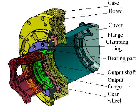
Bearing part
Case
Board
Output shaft Output flange Gear wheel
Cover
Flange
Clamping ring
Fig. 2. Structure diagram of EMB of SADM (section in an isometric projection)
Рис. 2. Силовая схема ЭМБ УПБС (разрез в изометрической проекции)
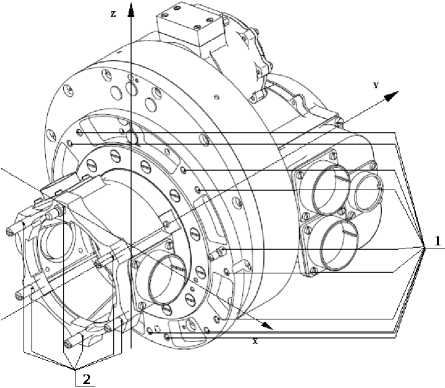
Fig. 3. Scheme of fixing EMB of SADM: 1 – places of fastening EMB of SADM to the spacecraft; 2 – places of fastening of a bar of the solar array with the electromechanical block of SADM
Рис. 3. Схема закрепления ЭМБ УПБС: 1 – места крепления ЭМБ УПБС к КА; 2 – места крепления штанги солнечной батареи с ЭМБ УПБС
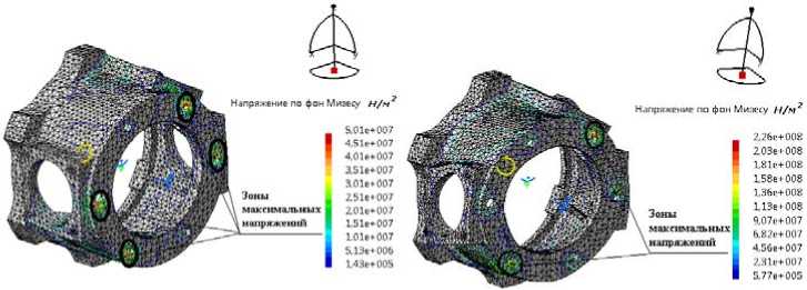
a b
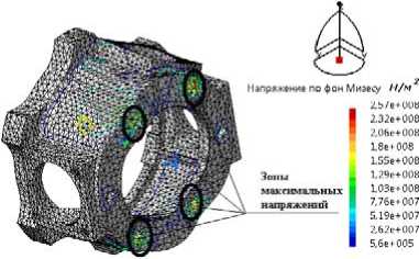
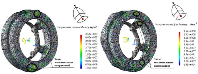
Fig. 4. Tensely deformed condition of an output flange: a – case of loading № 1; b – case of loading № 2; c – case of loading № 3
Рис. 4. Напряженно-деформированное состояние фланца выходного: а – случай нагружения № 1; б – случай нагружения № 2; в – случай нагружения № 3
a
b
c
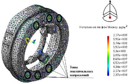
Fig. 5. Tensely deformed condition of an output shaft:
a – case of loading № 1; b – case of loading № 2; c – case of loading № 3
Рис. 5. Напряженно-деформированное состояние вала выходного: а – случай нагружения № 1; б – случай нагружения № 2; в – случай нагружения № 3
The results of statistic stress analysis of the output flange and the output shaft
|
№ Load case |
The element of the design |
Maximum stress σ экв , MPa |
Yield stress σ т , MPa |
Safty margin η |
|
1 |
The output flange |
50.1 |
490 |
9.78 |
|
The output shaft |
45.4 |
750 |
16.52 |
|
|
2 |
The output flange |
226 |
490 |
2.17 |
|
The output shaft |
157 |
750 |
4.78 |
|
|
3 |
The output flange |
257 |
490 |
1.91 |
|
The output shaft |
217 |
750 |
3.46 |
Conclusion. The output flange is added to the structure diagram of EMB of SADM of the spacecraft “Luna-Resurs-1” to increase its lifting power and for a more even load distribution. Optimization of the design of EMB of SADM was carried out, and as a result the mass of the node was reduced by 4.37 %. Stress analysis calculation of the main force elements is made. The electromechanical unit withstands specified loads with a safety margin of at least 1.91.
The work was financially supported by RFBR (grant No. 16-32-00302 mol_a), RFBR and the Government of the Krasnoyarsk Territory within the framework of the scientific project No. 16-42-243059 r_mol_а and № 16-42-240602 r_а, the programs of the Foundation for Assistance to Development of small forms of enterprises in the scientific and technical sphere (“UMNIK” Contract No. 6662UG2015 and No. 9607GU2015), scholarship of the President of the Russian Federation SP-317.2015.1.
References Stress analysis of solar array driver mechanism actuator of the spacecraft “Luna-Resurs-1”
- MOON. FACTS. Lunar elementals . URL: http://sci.esa.int/smart-1/31412-moon/.
- Wenzhe Fa, Ya-Qiu Jin. Quantitative estimation of helium-3 spatial distribution in the lunar regolith layer//Icarus. 2007. Vol. 190, No. 1. P. 15-23.
- SMART-1 . URL: http://sci.esa.int/smart-1/.
- SMART-1 mission to the moon: technology and science goals/B. H. Foing //Adv. Space Res. 2003. Vol. 31, No. 11. Pp. 2323-2333.
- The SELENE mission: goals and status/S. Sasaki //Adv. Space Res. 2003. Vol. 31, No. 11. Pp. 2335-2340.
- The Japanese lunar mission SELENE: Science goals and present status/M. Kato //Advances in Space Research. 2008. Vol. 42. Pp. 294-300.
- Goswami J. N., Annadurai M., Chandrayaan-1: India’s first planetary science mission to the moon//Current science. 2009. Vol. 96, No 4. Pp. 486-491.
- The Moon mineralogy mapper on Chandrayaan-1/M. Pieters Carle //Current science. 2009. Vol. 96, no 4. Pp. 500-505.
- China national space administration . URL: http://www.cnsa.gov.cn/.
- Фундаментальные космические исследования /Федеральное космическое агентство. URL: http://www.federalspace.ru/116/.
- Космический аппарат «Луна-Ресурс-1» . URL: http://www.laspace.ru/projects/planets/luna-resurs-oa/.
- Левантовский В. И. Механика космического полета в элементарном изложении. 3-е изд., доп. и перераб. М.: Наука, 1980. 512 с.
- Farside Gravity Field of the Moon from Four-Way Doppler Measurements of SELENE (Kaguya) Noriyuki Namiki/T. Iwata //Science. 2009. Vol. 323. Pp. 900-905.
- Improved Gravity Field of the Moon from Lunar Prospector/A. S. Konopliv //Science. 1998. Vol. 281, iss. 5382. Pp. 1476-1480.
- Чеботарев В. Е., Косенко В. Е. Основы проектирования космических аппаратов информационного обеспечения: учеб. пособие/Сиб. гос. аэрокосмич. ун-т. Красноярск, 2011. 488 с.
