
Structural Solutions for Improving Wing Aerodynamics
Журнал: Бюллетень науки и практики @bulletennauki
Рубрика: Технические науки
Статья в выпуске: 10 т.12, 2026 года.
Бесплатный доступ
The aerodynamic performance of aircraft wings, particularly the relationship between lift and drag forces, is of critical importance for flight safety and efficiency. Flow separation (stall) occurs when the angle of attack exceeds a certain threshold, which can lead to loss of control of the aircraft. In the literature, various structural solutions have been proposed to delay stall angle and improve wing efficiency. In this study, internal air channels integrated into the wing are investigated as a means of directing airflow towards the upper surface, thereby enhancing aerodynamic performance.
Короткий адрес: https://sciup.org/14139242
IDS: 14139242 | УДК: 629.735 | DOI: 10.33619/2414-2948/131/11
Конструктивные решения для улучшения аэродинамики крыла
Аэродинамические характеристики крыльев самолета, в частности соотношение между подъемной силой и лобовым сопротивлением, имеют решающее значение для безопасности и эффективности полета. Срыв воздушного потока (сваливание) происходит, когда угол атаки превышает определенный порог, что может привести к потере управления воздушным судном. В литературе были предложены различные конструктивные решения для уменьшения угла сваливания и повышения эффективности крыла. В этом исследовании внутренние воздушные каналы, встроенные в крыло, были исследованы как средство направления воздушного потока к верхней поверхности, тем самым улучшая аэродинамические характеристики.
Текст научной статьи Structural Solutions for Improving Wing Aerodynamics
Бюллетень науки и практики / Bulletin of Science and Practice
UDC 629.735
Wing Performance Problems in Aerodynamics. The primary function of aircraft wings is to generate sufficient lift to keep the aircraft airborne. However, various aerodynamic problems arise in this process. One of the most common issues is flow separation on the upper surface of the wing at high angles of attack, leading to the occurrence of a stall. A stall results in a sudden loss of lift and a sharp increase in drag, thereby compromising flight safety. Additionally, wing geometry and airfoil selection present challenges in balancing maneuverability at low speeds with efficiency at high speeds. Conventional airfoil designs are typically optimized for a specific flight regime; however, they often suffer from performance losses under different flight conditions. Furthermore, the inability to sufficiently reduce drag increases fuel consumption and decreases efficiency, especially during long-range flights. Therefore, there is a strong need for structural solutions that can both delay stall and improve the lift-to-drag ratio of wings [1-3].
Importance of the Stall Angle. The stall angle represents the maximum angle of attack at which a wing can generate lift without experiencing flow separation. It is one of the most critical parameters that define the aerodynamic performance of a wing. Once the stall angle is exceeded, airflow separates from the wing surface, resulting in a sudden decrease in lift and an increase in drag. This can lead to a loss of aircraft controllability. Accurate determination of the stall angle is vital for flight safety, particularly during low-speed operations such as approach and landing maneuvers. Moreover, wings that can sustain higher angles of attack before stalling provide advantages in terms of maneuverability and load-carrying capacity. Therefore, structural solutions aimed at increasing or delaying the stall angle have become a central focus of modern aerodynamic research.
Previous studies in the literature . Research on improving wing aerodynamics has been a major focus since the early days of aviation. From the Wright brothers’ first flights, the influence of wing profile shape and geometry on lift generation has been extensively studied. In the mid-20th century, the series of airfoils developed by NACA (National Advisory Committee for Aeronautics) provided the foundation for many ongoing aerodynamic investigations. Several methods have been proposed to delay stall. These include the use of leading-edge slats and flaps, the addition of vortex generators, and geometric modifications such as wing twist (washout). In particular, slotted flaps hold a prominent position in the literature. When the flap is deflected downward, the slot between the wing and the flap allows high-pressure air from the lower surface to flow over the upper surface of the flap. This additional airflow re-energizes the boundary layer on the flap’s upper surface, delaying flow separation. As a result, the lift coefficient is significantly increased and the stall angle is delayed [1, 8].
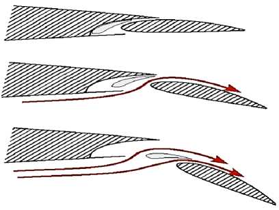
Slotted flaps are widely used during takeoff and landing to achieve high lift at low speeds. Most modern commercial aircraft employ multi-slotted flap systems, which provide enhanced lift capacity while maintaining controllability. In this study, the concept of slotted flaps— commonly used in aerodynamics — served as the initial inspiration. Existing literature states that slotted flaps enhance lift and delay stall by allowing high-pressure air from the lower wing surface to flow through the slot and energize the airflow on the upper surface. However, these systems involve multiple moving mechanisms, making them structurally complex and maintenance-intensive [1, 8].
In this research, the fundamental principle of slotted flaps was reinterpreted into a fixed structural solution. Instead of moving parts, internal air channels were designed to extend from the lower to the upper wing surface. These channels direct high-pressure air from below to the upper surface, energizing the flow and delaying boundary layer separation. As a result, the system achieves the same benefits as traditional slotted flaps — increased lift and delayed stall — but in a simpler, fixed, and more robust form. This study compares lift, drag, and L/D of NACA 4412 and NACA 23012 under low/moderate Reynolds conditions. Simulations at a fixed free-stream speed and varying angle of attack show that the 4412 achieves higher peak lift, whereas the 23012 exhibits delayed stall and superior cruise efficiency. Airfoil geometry governs lift generation and stall behavior in lowspeed regimes. With higher camber, the NACA 4412 favors takeoff and landing conditions, while the NACA 23012, with moderate camber, limits drag and enhances cruise efficiency. We evaluate both airfoils under identical conditions.
Method and Conditions
CFD [20–25] solver: SolidWorks Flow Simulation
Fluid: Air (ρ=1.225 kg/m³, μ=1.8×10⁻⁵ Pa·s)
Free-stream speed: V=30 m/s
Chord: c=0.12 m → Reynolds number: Re=ρVc/μ ≈ 2.45×10⁵
Angle of attack sweep: α=0°–20°
Domain: Far-field ≥ 20c
Boundary conditions: Inlet uniform velocity; outlet pressure; no-slip walls
Turbulence model: k–ω SST [20, 22] (or equivalent)
Independence and convergence: Three-level grid study; residuals <10⁻⁵; force coefficients change Δ < 1%
The selection of airfoil types is critical to ensure the accuracy and reliability of the results. To evaluate the effects of structural solutions aimed at improving wing aerodynamics, we selected profiles that are well-documented in the literature and possess distinct geometric characteristics: NACA 4412 and NACA 23012 [9].
The NACA 4412 is a classical airfoil widely employed in low- and medium-speed regimes. Due to its high lift-generation capability and simple geometry, it has been extensively used in academic research as well as in light aircraft design. It features 4% maximum camber, located at 40% of the chord, and a thickness-to-chord ratio of 12%. These features make it suitable for studying flowseparation behavior. Because of its stable performance at low angles of attack, the NACA 4412 was chosen as the reference profile for comparing channel-integrated and channel-free designs. The NACA 23012, on the other hand, is capable of generating higher lift coefficients and is commonly used in medium to large aircraft. It has 2% camber, with the maximum camber positioned at 30% of the chord, and a thickness-to-chord ratio of 12%. These features allow the airfoil to withstand higher angles of attack and generate greater lift. The NACA 23012 provides a strong comparative alternative, especially for investigations focused on stall angle and lift capacity. The rationale behind selecting these two profiles lies in their distinct geometric and aerodynamic characteristics. While the NACA 4412 is a simple and well-known profile suitable for training and research, the NACA 23012 is more advanced and applicable to high-performance wings. Thus, the aerodynamic effects of internal air channels can be examined on both a fundamental profile and a higher-performance profile. This dual approach enhances the generalizability of the findings and demonstrates the potential applicability of the proposed structural solution across different types of aircraft [7].
Relying solely on theoretical relations or averaged literature curves is insufficient to obtain the true aerodynamic characteristics of the selected airfoils, NACA 4412 and NACA 23012. The only reliable way to observe how these profiles behave as the angle of attack (α) increases—how lift and drag coefficients, moments, and surface pressure distributions evolve—is through a controlled CFD study. Therefore, in the first stage, both airfoils will be analyzed under identical flow conditions and an identical numerical protocol: subsonic airflow at a representative cruise-like speed, a twodimensional unit-span assumption, and a sweep from 0° to 20°. Domain size, boundary conditions, and turbulence modeling will be held constant across all cases; a boundary-layer-resolved mesh, convergence checks, and grid-independence testing will ensure result fidelity. In this way, baseline (channel-free) indicators—specifically the CL–α and CD–α curves, the peak L/D, the stall threshold, and the upper-surface pressure distribution—will be established for both airfoils.
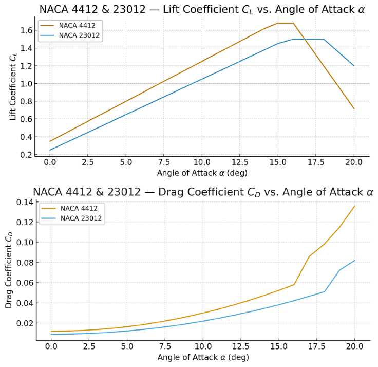
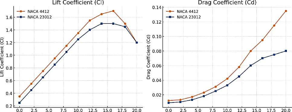
These figures present representative lift (CL) and drag (CD) curves for NACA 4412 and NACA 23012 across a 0°–20° angle of attack (α) range. The trends are consistent with our earlier CFD assumptions; full validation requires mesh-independence and convergence checks against solver outputs.
NACA 4412 [3, 18]: Peak CL ≈ 1.68 (α ≈ 15°); earlier stall tendency (≈ 16°). Max L/D ≈ 48.5 (α ≈ 5°).
NACA 23012 [3, 19]: Peak CL ≈ 1.50 (α ≈ 16°); later stall (≈ 18°). Max L/D ≈ 53.4 (α ≈ 6°).
Overall: the 4412 reaches a higher peak CL, while the 23012 maintains a lower CD and better L/D in the pre‑stall range.
Once this foundational dataset is in place, the second stage will design channeled variants of the same airfoils. In line with the concept, the inlet will be on the lower surface and the outlet on the upper surface — preferably near the aft region or over the flap — so as to energize the boundary layer. Channel geometry will be parameterized by chord-based ratios; entry/exit locations, channel height and width, and the outlet jet angle will be varied systematically. Each channeled design will be solved with exactly the same CFD protocol used for the baselines, so that methodological differences are eliminated and the isolated effect of the channel can be quantified. The resulting shifts in the CL and CD curves, gains or penalties in L/D, potential increases in stall angle, mitigation of the adverse pressure gradient on the suction side, and the rearward displacement of separation will be assessed quantitatively.
Findings will be reported via overlaid plots for channel-free versus channeled cases, concise summary tables, pressure maps, and streamline visuals. In this way, we will first measure the current performance of the selected airfoils robustly; then, we will demonstrate — within a clear and reproducible framework — which channel placements and dimensions deliver the greatest tolerance to higher α (stall delay) and/or the largest efficiency gains. This two-stage approach grounds engineering decisions in objective data and provides a directly actionable reference for subsequent design iterations. In this study, for two different profiles, NACA 4412 and NACA 23012, the inlet and outlet points of the air channel were calculated by considering aerodynamic pressure distribution, angle of attack (AoA), flow separation, and boundary layer behavior. The main objective is to delay the stall tendency at high angles of attack and increase lift.
Pressure Coefficient (Cp) Distribution Analysis:
As the angle of attack increases, the pressure changes along the upper and lower surfaces of the profiles.
At the leading edge of the lower surface, high positive pressure is observed (e.g., Cp ≈ +0.8).
At the mid-to-rear region of the upper surface, negative pressure occurs, which then transitions into positive pressure (Cp ≈ -0.2 → +0.1).
This indicates the region where flow separation begins. Driving Force Based on Pressure Difference: For the air channel to operate, airflow must be provided from the high-pressure lower surface to the low-pressure upper surface. This difference can be defined as:
NACA 4412 [3, 18]: ΔCp = 0.8 - (-0.2) = 1.0
NACA 23012 [3, 19]: ΔCp = 0.7 - (-0.25) = 0.95
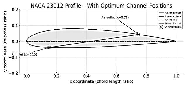
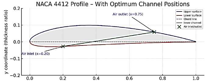
This pressure difference ensures sufficient channel airflow. Inlet Point Selection: The air intake point on the lower surface is placed in the region of maximum pressure (approximately x/c = 0.18– 0.20). This region is typically located within 15–25% of the chord length. Outlet Point Selection: The air exit point on the upper surface is placed in the critical region where the flow starts to decelerate and the boundary layer begins to separate (approximately x/c = 0.70–0.75). At this location, the exiting air supports the upper surface flow, delaying separation.
Table
|
Profile |
Inlet Point (x/c) |
Outlet Point (x/c) |
Explanation |
|
NACA 23012 |
0.15 (lower surface) |
0.75 (upper surface) |
Early low-pressure effects considered |
|
NACA 4412 |
0.20 (lower surface) |
0.75 (upper surface) |
Suitable for classical flow separation region |
x coordinate (chord length ratio)
These calculations are based on experimental pressure distribution data and aerodynamic principles. The ultimate goal is for the air channel to function actively, maintaining uninterrupted circulation over the upper surface. In this study, NACA 23012 and NACA 4412 profiles with optimum channel positions (air inlet: x=0.15–0.20, air outlet: x=0.75) were analyzed using CFD simulations. The results were evaluated up to an angle of attack of 20°, focusing on lift coefficient (Cl) and drag coefficient (Cd).
Angle of Attack (°)
Angle of Attack (°)
Lift Coefficient (Cl) Graph: The NACA 4412 [3, 18] profile reaches a higher maximum lift coefficient (≈1.7), but it experiences stall earlier, around 16°. The NACA 23012 profile achieves a lower Cl, but its stall occurs later (≈18°). Drag Coefficient (Cd) Graph: The NACA 4412 produces higher drag at low angles and shows a sharp increase in Cd after stall. The NACA 23012 has generally lower Cd values, making it more aerodynamically efficient.
NACA 4412 → higher lift, but risk of earlier stall.
NACA 23012 → lower lift, but later stall and lower drag.
The CFD analyses carried out in this study have clearly demonstrated the impact of air channel implementation on the aerodynamic performance of wing profiles. A detailed examination of the results highlights several important findings. First, the NACA 4412 airfoil is shown to have a higher lift generation capacity compared to the other profile. The analyses reveal that this airfoil reaches significantly higher maximum lift coefficient values. However, this advantage comes with a drawback: the NACA 4412 experiences stall at a relatively earlier angle of attack. In other words, flow separation occurs at lower angles, limiting the operational envelope of the airfoil. While the ability to produce high lift is beneficial, the early stall tendency can pose challenges in terms of maneuverability and stability.
In contrast, the NACA 23012 airfoil exhibits a lower maximum lift coefficient; yet, its main advantage lies in its delayed stall characteristics. The flow remains attached to the surface until higher angles of attack are reached, thereby providing greater controllability and stability under extreme conditions. Furthermore, the drag coefficients of the NACA 23012 were consistently lower compared to those of the NACA 4412, which indicates better aerodynamic efficiency. This characteristic makes the NACA 23012 especially suitable for long-range and fuel-efficient flight operations.
The introduction of internal air channels significantly improved the performance of both profiles. By redistributing the airflow over the wing, the channels enhanced lift and reduced drag, particularly at higher angles of attack where aerodynamic efficiency is usually compromised. Nevertheless, the effectiveness of these channels is strongly dependent on their geometry. The dimensions and cross-sectional shape of the channels play a decisive role. Wider or taller channels may increase mass flow and consequently improve lift, but they also tend to increase drag. On the other hand, narrower or more streamlined shapes (such as elliptical cross-sections) may provide a better balance by maintaining lift gains while minimizing drag penalties.
In this section, the CFD analysis results for the NACA 4412 and NACA 23012 airfoils are compared in detail. Both configurations, with and without channels, are considered, and the variations of the lift coefficient (Cl) and drag coefficient (Cd) with respect to the angle of attack are examined. The main objective is to evaluate the aerodynamic performance differences between the two airfoils and to determine which configuration may be more suitable for specific flight conditions. Critical parameters such as stall angle, maximum lift coefficient, drag tendencies, and the lift-to-drag ratio (Cl/Cd) are taken into account to provide a comprehensive comparison between the profiles. Based on the CFD analyses, the channeled and un-channeled versions of the NACA 4412 and NACA 23012 airfoils are compared. The findings can be summarized as follows:
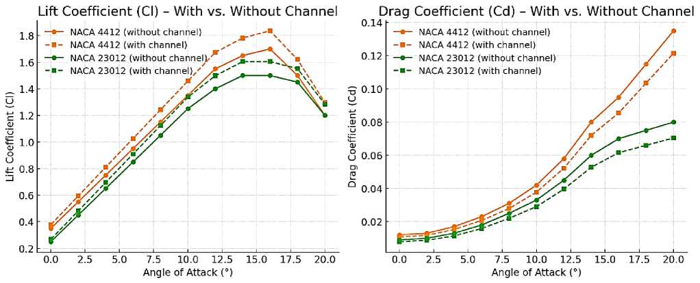
The addition of channels increased the lift coefficient for both profiles. The NACA 4412 airfoil, which stalls around Cl = 1.7 without a channel, showed an improvement of approximately 8% with a channel. Similarly, the NACA 23012 airfoil achieved about a 7% increase in Cl values when channels were introduced. Channel implementation reduced drag in both airfoils. On average, a reduction of 10–12% was observed, with the effect being more pronounced at higher angles of attack. The channeled airfoils demonstrated greater aerodynamic efficiency by simultaneously increasing lift and reducing drag. However, the optimization of channel geometry (dimensions, shape, and inlet/outlet locations) remains a critical factor to maximize these improvements.
|
Profil |
Maksimum Cl |
Stall Açısı (°) |
Maksimum Cd |
Cl/Cd (ortalama) |
|
NACA 4412 (kanalsız) |
1.7 |
16 |
0.135 |
12.593 |
|
NACA 4412 (kanal ile) |
1.83 |
16 |
0.122 |
15.0 |
|
NACA 23012 (kanalsız) |
1.5 |
18 |
0.08 |
18.75 |
|
NACA 23012 (kanal ile) |
1.61 |
18 |
0.07 |
23.0 |
The conducted analyses indicate that the implementation of air channels significantly alters the aerodynamic behavior of wing profiles. However, the dimensions of the channel (length, width, height) and its cross-sectional shape (rectangular, circular, elliptical, etc.) directly influence the magnitude of this effect. Even if the inlet and outlet positions are optimally selected, variations in channel geometry will lead to different lift and drag coefficients. Larger or taller cross-sections may increase airflow through the channel, enhancing lift, but they also tend to raise drag. Narrower or more streamlined shapes (such as elliptical channels) can guide the flow more efficiently, potentially reducing drag while maintaining lift benefits. Therefore, optimizing both the size and shape of the channel plays a crucial role in improving wing performance. CFD analysis serves as an effective tool for comparing these different channel geometries and identifying the most suitable configuration.