Study of a laboratory circuit with a warm baseboard in pulse mode

Author: Yang Ch.
Journal: Бюллетень науки и практики @bulletennauki
Section: Технические науки
Article in issue: 6 т.10, 2024.
Free access
The increasing global energy demand is a problem that people have been paying attention to, people’s demand for energy is increasingly urgent, and improving energy efficiency has become a hot topic in this century. Studies have shown that pulsating flow has an important effect on heat transfer, and it has been concluded in most literatures that turbulent pulsation can enhance heat transfer in different degrees. Pulsation heat transfer is a comprehensive heat transfer process, and the best heat transfer performance can be achieved only when the thermal resistance of each part is reasonably coordinated. Based on the principle of hydraulic shock, this paper develops a device with warm substrate which can be used to increase the pulsating pressure and enhance the heat transfer efficiency of pulsating flow. Firstly, the construction scheme of the experimental device is proposed, and the working principle of the experimental device is described in detail. The complex impedance, frequency function, amplitude-frequency characteristic and phase-frequency characteristic are obtained by mathematical transformation of power supply circuit. Finally, the frequency response of the circuit is constructed.
Hydraulic, heat exchanger, heat, flow, heat transfer
Short address: https://sciup.org/14130177
IDR: 14130177 | UDC: 662.99 | DOI: 10.33619/2414-2948/103/36
Исследование лабораторного контура с теплым плинтусом в импульсном режиме
Растущий мировой спрос на энергоносители является проблемой, которая постоянно беспокоит людей, которые все более остро нуждаются в энергии, и повышение энергоэффективности стало актуальной темой в этом столетии. Исследования показывают, что пульсирующие потоки оказывают важное влияние на конвертируемое тепло, и большинство документов считают, что турбулентные пульсации могут повысить степень теплообмена. Пульсирующий теплообменный процесс - это комплексный процесс теплообмена, который может быть наилучшим для достижения оптимальной тепловой эффективности только в рациональной координации всех компонентов сопротивления нагрева. Основанной на принципе гидравлического шока разработана установка для повышения пульсирующего давления и повышения тепловой эффективности пульсирующих потоков. Во-первых, были предложены планы по созданию экспериментального устройства и детальное описание того, как оно работает. Математическое преобразование электрических схем дает сложные импедансы, частотные функции, частотные характеристики амплитуды и фазовые частотные характеристики. Наконец, был построен частотный ответ цепи.
Text of the scientific article Study of a laboratory circuit with a warm baseboard in pulse mode
Бюллетень науки и практики / Bulletin of Science and Practice
UDC 662.99
The increasing global energy demand is a problem that people have been paying attention to, people's demand for energy is increasingly urgent, and improving energy efficiency has become a hot topic in this century. Studies have shown that pulsating flow has an important impact on heat transfer, and it has been concluded in most literatures that turbulent pulsation can enhance heat transfer effect to varying degrees [1-3]. Pulsation heat transfer is a comprehensive heat transfer process, and the best heat transfer performance can be achieved only when the thermal resistance of each part is reasonably coordinated. A. P. Levtsev, A professor at the University of Moldova in Russia, applied various pulsation generation devices in the field of heat transfer. The experimental results show that when the flow rate of the refrigerant is 0.5m3/h and the pulsation frequency is 15Hz, the pulsation flow increases the heat transfer coefficient of the system by 24% [4]. Pulsed heat transfer is a special fluid pulsation enhanced heat transfer technology [5], which is a typical representative of non-fixed process related to flow and heat transfer technology [6-8]. How to improve heat flux by pulsating flow technology has become the most concerned issue today. Therefore, it is necessary to design a device with warm substrate which can be used to increase the pulsating pressure and enhance the heat exchange efficiency of the pulsating flow, so as to achieve the purpose of improving the heat exchange efficiency. Pulsating heat transfer mode saves equipment operation and maintenance costs, improves economic benefits, and has high engineering value and wide application prospects in the field of waste heat recovery and central heating [9].
This study puts forward reasonable suggestions for the design of heating pipeline, describes the working principle of the experimental device in detail, and draws a simplified power circuit diagram, which has guiding significance for the fine adjustment of hydraulic energy circuit and heating energy circuit.
Materials and Methods
On the basis of the above review and analysis, the circuit scheme of the experimental device with heat carrier pulse supply mode is developed. This solution is shown in Figure 1. The laboratory unit is designed to perform hydraulic and thermal tests of hot springs at frequencies up to 5Hz and heat carrier flows up to 360 L/min.
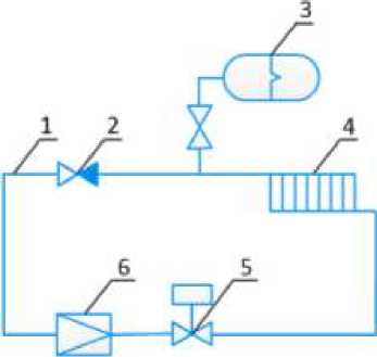
Figure 1. Laboratory circuit with a warm baseboard in pulse mode: 1 – pipeline; 2 – check valve; 3 – hydraulic accumulator; 4 – water baseboard; 5 – solenoid valve; 6 – water meter
When the solenoid valve 5 is abruptly closed, the kinetic energy of the flow tums into potential (pressure increase) valve of increased pressure goes along the chain; a warn plinth hydraulic accumulator 3. A valve of increased pressure in the plinth increases its heat transfer, then it enters the accumulator.
Before starting work, pipeline 1 is ruptured and connected to the heat network (the heat network is not shown in the diagram). The circuit is filled with a coolant and the air is removed. Due to the pressure difference in the heat network in the circuit, the coolant begins to flow through the circuit: the supply pipeline of the heat network, the check valve 2, the warm baseboard 4, the solenoid valve 5, the water meter 6, the return pipeline of the heat network. The coolant passing through the warm baseboard gives off heat to the surrounding air and reduces the temperature itself. Next, electrical power is supplied to the actuator of the solenoid valve 5 and it will close quickly. At the same time, the pressure increases in front of the solenoid valve 5 due to the transition of the kinetic energy of the flow to the potential. When the pressure reaches its maximum, its reverse wave will go in the opposite direction through the warm baseboard 4 and improve heat transfer in it, and the excess wave will be extinguished in the accumulator 3.
In the course of the study, for a better understanding of the scheme, it was decided to study 2 characteristics of hydraulic and thermal, in order to better understand the nature of the forces arising and to more accurately determine the required parameters on the obtained model.
The temperature range for a warm baseboard is 40-80 degrees Celsius. The temperature range for a warm baseboard is 40-80 degrees Celsius. Set the heat flow temperature to 80°C, the parameters are automatically recorded during the test. See Table 1-Table 4.
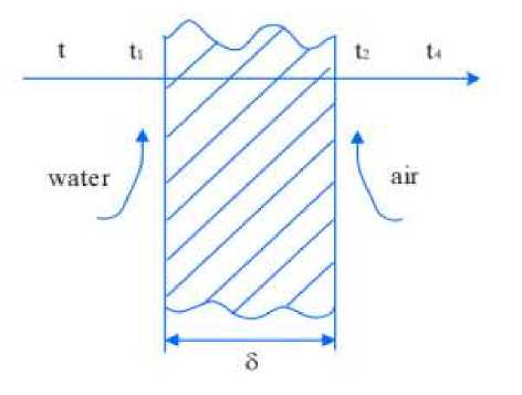
Figure 2. Part of the heat transfer plant: t – the temperature of hot water; t 1 , t 2 – wall temperature; t 3 – the temperature of the air; α1 – convective heat transfer coefficient of water and left wall; α2 – convective heat transfer coefficient of air and right wall; δ – the thickness of the wall surface; λ – Thermal conductivity of the wall
Results and discussion
CIRCUIT PARAMETERS
Table 1
|
m, kg |
r^N/m • s |
r 2 ,N/m • s |
1 1 , lit • s/kPa |
l2, lit • s/kPa |
P30,kPa |
V 30 , lit/s |
|
20 |
500 |
1000 |
0.0017 |
0.017 |
200 |
20 |
|
20 |
1000 |
1000 |
0.0017 |
0.017 |
200 |
20 |
|
40 |
500 |
1000 |
0.0017 |
0.017 |
200 |
40 |
Dependency graphs are plotted based on the input values. For the best perception of graphs values are taken only those that affect the dependence. The values obtained for the first stage of the energy circuit are shown in Table 2.
Table 2
|
Ω |
Л 1 (Д2) |
Ф10Л) |
A2W |
Ф2ОЛ) |
Л3(Д2) |
ФзОЛ) |
|
1 |
647.946 |
1.237 |
1163.838 |
1.223 |
659.542 |
1.226 |
|
2 |
2620.540 |
1.231 |
705.372 |
1.278 |
1448.755 |
1.211 |
|
3 |
331.363 |
1.288 |
260.215 |
1.346 |
273.252 |
1.271 |
|
4 |
180.043 |
1.339 |
164.557 |
1.393 |
158.650 |
1.329 |
|
5 |
127.116 |
1.378 |
122.861 |
1.425 |
119.368 |
1.376 |
|
6 |
100.506 |
1.408 |
99.418 |
1.449 |
101.560 |
1.412 |
|
7 |
84.676 |
1.431 |
84.395 |
1.466 |
93.170 |
1.440 |
|
8 |
74.341 |
1.449 |
73.987 |
1.479 |
90.223 |
1.462 |
|
9 |
67.219 |
1.464 |
66.404 |
1.490 |
91.280 |
1.479 |
|
10 |
62.053 |
1.476 |
60.691 |
1.499 |
96.059 |
1.494 |
RECEIVED INFORMATION FOR HYDRADULIC
Based on the results of the calculation, the graphs of the amplitude frequency response and phase-frequency response and frequency response of the circuit are constructed. Further in these graphs are under construction.
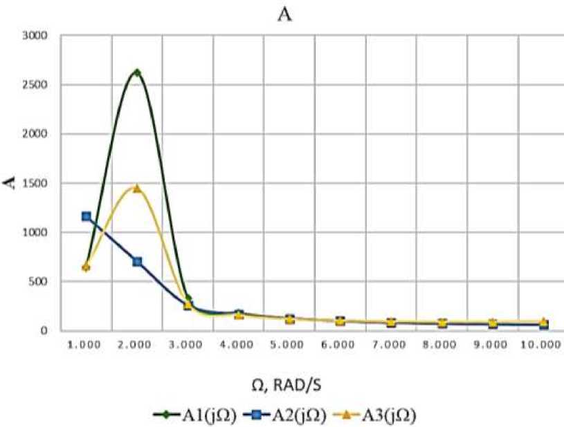
Figure 3. Amplitude frequency response
(се) Ф
ɸ
ɸ1(jΩ) ɸ2(jΩ) ɸ3(jΩ)
-
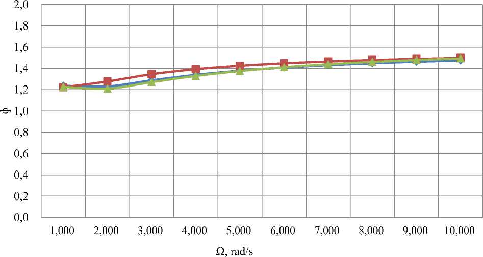
Figure 4. Phase frequency response
For power circuits of the heat transfer calculations are conducted similarly and are written in Table 4. A graphical view is presented in graphs 5-6.
RECEIVED INFORMATION FOR HEAT TRANSFER
VALUE AMPLITUDE FREQUENCY RESPONSE FOR ENERGY CIRCUIT
Table 3
|
n0, kW |
r 1 ,C 2 /W |
r2,°C 2 /W |
r3,C2/W |
c 1 , W/0C 2 |
c2,W/C2 |
to°C |
|
1.70 |
0.000625 |
0.0000071 |
0.05 |
0.053 |
0.053 |
80 |
|
1.70 |
0.000625 |
0.0000071 |
0.10 |
0.053 |
0.053 |
80 |
|
1.70 |
0.000625 |
0.0000071 |
0.05 |
0.530 |
0.530 |
80 |
Table 4
|
Ω |
A i (jO) |
Ф 1 (j^) |
A 2 (jO) |
Ф2^Ф) |
Аз№ |
Фз№ |
|
1 |
0.051 |
0.003 |
0.101 |
0.005 |
0.051 |
0.026 |
|
2 |
0.051 |
0.005 |
0.101 |
0.011 |
0.051 |
0.053 |
|
3 |
0.051 |
0.008 |
0.101 |
0.016 |
0.050 |
0.079 |
|
4 |
0.051 |
0.011 |
0.101 |
0.021 |
0.050 |
0.106 |
|
5 |
0.051 |
0.013 |
0.101 |
0.026 |
0.050 |
0.132 |
|
6 |
0.051 |
0.016 |
0.101 |
0.032 |
0.050 |
0.158 |
|
7 |
0.051 |
0.019 |
0.101 |
0.037 |
0.050 |
0.183 |
|
8 |
0.051 |
0.021 |
0.101 |
0.042 |
0.049 |
0.209 |
|
9 |
0.051 |
0.024 |
0.101 |
0.048 |
0.049 |
0.234 |
|
10 |
0.051 |
0.026 |
0.100 |
0.053 |
0.049 |
0.259 |
0,11
0,10
A
0,09
0,08
0,07
0,06
0,05*--*--A--A---A---A-- 111 j
< 0,04
0,03
0,02
0,01
0,00
1,000 2,000 3,000 4,000 5,000 6,000 7,000 8,000 9,000 10,000
Ω, rad/s
A1(jΩ)
-■-A2(jΩ)
A3(jΩ)
-
Figure 5. Amplitude frequency response
0.20
0.10
0.05
-e«o is

1.000 2.000 3.000 4.000 5.000 6.000 7.000 8.000 9.000 10.000
Q, RAD/S
ф1йЯ)
ф2^£1) -^фЗ({П)
-
Figure 6. Phase frequency response
Conclusion
In the course of the work, the problems associated with this work and possible solutions are described. A constructive scheme of the experimental device is proposed and the principle of its operation is described in detail. The power circuit of the device is drawn up, each link is explained. Complex impedance, frequency function, amplitude-frequency characteristic and phase-frequency characteristic are obtained by mathematical transformation of the power circuit. The frequency response of the circuit is constructed.
In the process of modeling the hydraulic power circuit, it is found that with the increase of frequency, the frequency response of the hydraulic circuit first increases and then decreases, and finally becomes stable, and the amplitude gradually increases in this process. It can be found that after the parameter r is changed, the frequency response of the hydraulic circuit reaches a peak in advance, and then gradually decreases, while changing the water mass has little effect on this. The changes of parameters r and water mass have little effect on the amplitude, and both show a trend of gradual increase.
In the process of heat transfer modeling of energy circuit, it is found that the frequency response of hydraulic circuit gradually decreases with the increase of frequency, resulting in uniform pulsation, in which the amplitude gradually increases. It can be found that the frequency response changes the most when the resistance r value is changed, and the amplitude changes the most when the capacitance c is changed. It can be found that after the change of parameter r, the frequency response of the hydraulic circuit in the heat transfer model increases overall, but still presents a trend of gradual decrease, resulting in uniform pulsation. The change of parameter c has little impact on the frequency response of the hydraulic circuit in the heat transfer model, but it can be seen that the decrease speed is slightly faster. The change of parameters r and c has a great influence on the amplitude, in which the amplitude increases with the increase of frequency as follows: ф3 (j И ) > ф2 (j £1 ) > ф 1 (j /2 ).
Sources:
-
(1) . Experimental study on heat exchange performance of pulsed flow enhanced plate heat exchanger. https://oss.wanfangdata.com.cn/www/
-
(2) . Simulation analysis and experimental study of pulsating heat transfer system based on a new type diaphragm booster device. https://oss.wanfangdata.com.cn/www/
-
(3) . Modern problems of science and education. https://rae.ru/
References Study of a laboratory circuit with a warm baseboard in pulse mode
- Edwards M. F., Wilkinson W. L. Review of potential applications of pulsating flow in pipes // Transactions of the Institution of Chemical Engineers and the Chemical Engineer. 1971. V. 49. №2. P. 85-&.
- Evans N. A. Heat transfer through the unsteady laminar boundary layer on a semi-infinite flat plate Part II: Experimental results from an oscillating plate // International Journal of Heat and Mass Transfer. 1973. V. 16. №3. P. 567-570. DOI: 10.1016/0017-9310(73)90224-X
- Ahčin Ž., Liang J., Engelbrecht K., Tušek J. Thermo-hydraulic evaluation of oscillating-flow shell-and-tube-like regenerators for (elasto) caloric cooling // Applied Thermal Engineering. 2021. V. 190. P. 116842. DOI: 10.1016/j.applthermaleng.2021.116842 EDN: BSXIEZ
- Макеев А. Н., Левцев А. П. Импульсные системы теплоснабжения общественных зданий // Региональная архитектура и строительство. 2010. №2. С. 108-114. EDN: MXHSVX
- 张亮 张安龙, 曲平平 荆宇燕. 脉动流场下波壁管内流体流动与换热特性 //科学技术与工程. 2022. V. 22. №1. P. 173-178.
- Левцев А. П., Макеев А. Н. Импульсные системы тепло- и водоснабжения. Саранск: Изд-во Мордовского ун-та, 2015. 171 с.
- Левцев А. П., Макеев А. Н., Макеев Н. Ф., Нарватов Я. А., Голянин А. А. Обзор и анализ основных конструкций ударных клапанов для создания гидравлического удара // Современные проблемы науки и образования. 2015. №2-2. С. 188-188. EDN: UZJAOV
- Левцев А. П., Макеев А. Н., Кудашев С. Ф. Импульсные системы теплоснабжения // Энергоэффективные и ресурсосберегающие технологии и системы. 2010. С. 3-7. EDN: WLGIUH
- 周迎真.基于新型膜增压装置的脉动传热系统仿真与实验研究. 江苏 江苏科技大学 2020.
