Study on the effect of diaphragm booster on the pulsed heat transfer of cooling system

Author: Zhou Yingzhen, Liu Zuncheng, Golyanin Anton
Journal: Бюллетень науки и практики @bulletennauki
Section: Технические науки
Article in issue: 4 т.6, 2020.
Free access
This paper has developed a diesel engine cylinder liner and cooling water heat exchange enhancement device, including diesel engine cylinder liner, cylinder liner water cooler, hydraulic accumulator, check valve, diaphragm booster, centrifugal water pump, pulse valve and Conical tube. As well as the pulsating circulation system and booster system composed of equipment. The device heats the heat generated by the diesel engine cylinder liner in a pulsating circulation system through a cylinder circulator in a pulsating circulation system to exchange heat with the external low-temperature seawater. By controlling the opening and closing of the pulsating valve in the pulsating circulation system, fluid is generated in the pipe. Pulsing and hydraulically impacting the diaphragm booster connected near the pulsation valve pipeline, the fluid at the outlet of the diaphragm booster is subjected to hydraulic shock and circulates in a closed booster circuit connected to the diaphragm booster and passes through the cone during the flow...
Membrane pump, electric drive, hydraulic drive, pipe pulsation
Short address: https://sciup.org/14116207
IDR: 14116207 | UDC: 533.6.011.6 | DOI: 10.33619/2414-2948/53/25
Исследование влияния диафрагменного усилителя на импульсный теплообмен системы охлаждения
В данной статье были разработаны гильза цилиндра дизельного двигателя и устройство для улучшения теплообмена охлаждающей воды, в том числе гильза цилиндра дизельного двигателя, охладитель воды в гильзе цилиндра, гидравлический аккумулятор, обратный клапан, гидроусилитель мембраны, центробежный водяной насос, импульсный клапан и коническая трубка. Также пульсирующая система циркуляции и бустерная система в составе оборудования. Устройство нагревает тепло, генерируемое гильзой цилиндра дизельного двигателя в пульсирующей циркуляционной системе, через циркуляционный цилиндр в пульсирующей циркуляционной системе для обмена теплом с внешней низкотемпературной морской водой. Посредством управления открытия и закрытия пульсирующего клапана в пульсирующей циркуляционной системе в трубе образуется жидкость. Импульсное и гидравлическое воздействующее на усилитель диафрагмы, соединенный рядом с трубопроводом клапана пульсации, жидкость на выходе из усилителя диафрагмы подвергается гидравлическому удару и циркулирует в замкнутом контуре усилителя, соединенном с усилителем диафрагмы, и проходит через конус во время потока...
Text of the scientific article Study on the effect of diaphragm booster on the pulsed heat transfer of cooling system
Бюллетень науки и практики / Bulletin of Science and Practice
In the study of pulsating heat transfer, the average speed of the pulsating flow, the pulsating frequency, and the pulsating amplitude can be controlled by adjusting the speed of the motor to enhance the heat transfer [1]. However, because of the frequency modulation of the motor and the transmission of fluid by the pipeline pump, electrical energy is required, and energy consumption is high [2]. The traditional pulsation generating device generally adopts a method such as a solenoid valve or a reciprocating pump. The method of enhancing heat exchange efficiency by consuming additional energy makes the energy saving effect not ideal, resulting in the limitation of active enhanced heat exchange in practical applications [3]. Therefore, improving the heat exchange efficiency of the heating system and reducing the energy consumption of the pulsation device has become a problem for the pulsation heat exchange technology [4]. Since pulsation–enhanced heat transfer belongs to active intensified heat transfer in the classification of convection-enhanced heat transfer technology, additional mechanical energy is required to perform work during heat exchange, which increases efficiency while increasing new energy consumption [5].
Material and research methods
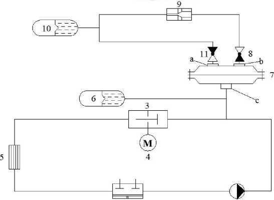
As shown in Figure 1, a marine diesel engine cylinder liner and cooling water heat exchange enhancement device includes a diesel engine cylinder liner 1, a cylinder liner water cooler 5, a centrifugal water pump 2, an electric motor 4, a pulsation valve 3, and a first check valve 8, A second check valve 11, a diaphragm booster 7, a conical tube 9, a first hydraulic accumulator 6, a second hydraulic accumulator 10, which are characterized by a diesel engine cylinder liner 1 and a centrifugal water pump 2, a pulsation valve 3. The cylinder liner water cooler 5 and the first hydraulic accumulator 6 constitute a pulsating circulation system of cooling water. The cooling water in the diesel cylinder liner 1 is connected to the centrifugal water pump 2 through a pipeline, and a pulsation valve 3 is installed in the pipeline behind the centrifugal water pump 2. The first hydraulic accumulator 6 is connected between the centrifugal water pump 2 and the pulsation valve 3. To compensate for the pressure fluctuations of the pulsating circulation system in the pipeline, the motor 4 is installed on the pulsation valve 3 to control the pulsation valve to open and close periodically. The cooling water that cools the diesel engine passes through the cylinder liner 1 of the diesel engine and flows out of the pipeline and is sucked in by the inlet of the circulating pump 2 and continues to flow through the pipeline through the pulsation valve 3 to generate a hydraulic shock to form a pulsating flow [6]. The generated pulsating flow flows through the pipeline to the cylinder liner water. The cooler 5 is cooled by sea water. The cooled cooling water enters the diesel engine cylinder liner 1 along the pipeline again to form a closed pulsating cycle. The supercharging system consisting of the diaphragm supercharger 7 and the tapered tube 9 and the second hydraulic accumulator 10 is connected to the inlet of the pulsation valve 3 through the inlet of the diaphragm supercharger 7 [7]. A second check valve 11 is connected to an outlet a, and a first check valve 8 is connected to the second outlet b. The conical tube 9 is connected to the pipeline behind the first check valve 8, and the second hydraulic accumulator 10 is connected to the pipeline behind the conical tube 9 to compensate for pressure fluctuations in the booster system. At the moment when the pulsation valve 3 is closed, there is a sharp pressure jump in the pipe, and the fluid thereby forms a pulse pointing in the opposite direction to the flow direction [8].
The cooling water is guided to the elastic diaphragm of the diaphragm supercharger 7 at high speed. The fluid that forms a hydraulic shock under the action of the water hammer flows under pressure to the inlet c of the diaphragm supercharger 7 and enters the lower cavity of the diaphragm supercharger 7 to deform the elastic diaphragm. After the elastic diaphragm is deformed, the liquid in the cavity of the diaphragm supercharger 7 is pushed through the first one-way valve 8, and the fluid flows to the conical tube 9 through the first one-way valve 8. The large static pressure decreases, and the second hydraulic accumulator 10 connected to the conical tube 9 will compensate for the pressure fluctuation of the liquid [9]. After the speed increases, the fluid continues to flow along the pipeline to the second one-way valve 11. After passing through the second one-way valve 11, it flows back to the diaphragm supercharger 7 and impacts the elastic diaphragm [10]. Boost cycle. At this time, the pressure in the pulsating circulation system increases due to the effect of the elastic diaphragm, so the velocity of the pulsating fluid increases due to the pressure rise, and the heat exchange efficiency will also increase after the speed increases.
1 2
Figure 1. Experimental installation diagram .
As shown in Figure 2, the exterior of the diaphragm booster 7 is composed of a lower cavity 7-1 having an inlet c and an upper cavity 7-5 having a first outlet a and a second outlet b. The lower cavity 7-1 is of equal height design. The upper cavity 7-5 is a cylindrical shell without a bottom surface. The top circular surface has two symmetrical first and second outlets a and b. It is connected with the lower cavity 7-1 by screws. The lower cavity 7-1 is a rounded truncated shell without a top surface. The diameter of the top surface is larger than the diameter of the bottom surface. The diameter of the top surface is the same as the diameter of the upper cavity 7-5. The top is also symmetrical to the upper cavity 7-5. The flange has a fluid inlet c at the bottom circle center. A circular elastic diaphragm 7-2 having a diameter larger than the diameter of the bottom surface of the upper cavity 7-5 is located inside the diaphragm supercharger 7 and is fixed between the lower cavity 7-1 and the upper cavity 75 by screws. Separated and sealed at the flange to prevent fluid leakage. Insert a hollow bolt 7-6 at the top circle center of the upper cavity 7-5 and fix it with the upper cavity 7-5. The solid bolt 7-4 is fixed to the circle center of the elastic diaphragm 7-2 by the support washer at the bottom. And into the hollow bolt 7-6 on the other side. The adjusting spring 7-3 is sleeved on the solid bolt 7-4, the top is supported by the hollow bolt 7-6, and the bottom is supported by the washer. When a water hammer occurs at the source of the fluid pulsation, its positive wave will ensure that the elastic diaphragm 7-2 moves upward, which overcomes the rigidity of the elastic diaphragm 7-2. At the moment when the positive wave of the water hammer changes the sign to the opposite, the elastic diaphragm 7-2 will move downward under the action of the elastic force of the adjustment spring 7-3 [11]. Therefore, a part of the newly injected fluid will enter the upper cavity 7-5 of the diaphragm supercharger 7 through the first outlet a of the diaphragm supercharger 7. After that, the working process of the diaphragm booster 7 will be completely repeated in the above order [12].
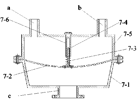
Figure 2. Diaphragm booster schematic.
In this experiment, three groups of different pulsating frequencies were analyzed, and the effects of the presence or absence of a diaphragm booster on the pulsating pressure of the pipeline were compared at the same pulsating frequency. The three sets of pulsating frequencies in the experiment were f1; the flow rate in the pipeline was f1=1.43Hz , f2=1.70Hz , f3=2.85Hz; the flow in the pipeline is 0.000182 m3/s, 0.00022 m3/s. The cylinder liner of the diesel engine selected for the experiment is SD1125 series direct injection single cylinder diesel cylinder liner. The selected centrifugal water pump is the WILO TOP-S40/10 centrifugal water pump made in Germany. The pulsation valve is a VFR camshaft valve produced by Chongqing Chuanyi Regulating Valve Co., Ltd. The first and second hydraulic accumulators are both diaphragm type hydraulic accumulators in gas hydraulic accumulators. In this experiment, the heat exchanger is a self-designed spiral coil heat exchanger. Figure 3 shows the overall setup of the experimental system.
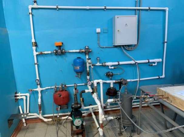
Figure 3. Shows the overall setup of the experimental system.
Results and discussion
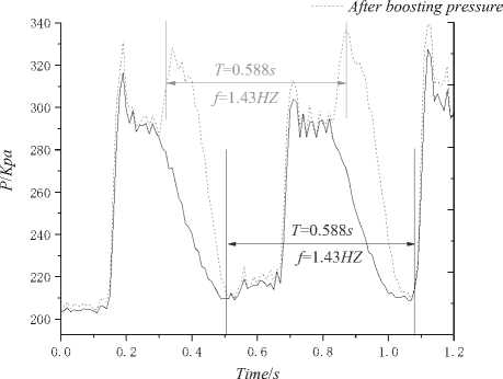
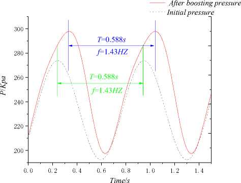
Through the pulsation boosting heat transfer experiment, the change curves of the pressure increase value of the diaphragm supercharger with time at different pulsation frequencies were obtained. The change curves of the pipe pressure before and after the boost were compared [13]. The pressure was obtained by analyzing the experimental data Change as a function of time.
a) b)
Figure 4. The relationship between the experimental pressure curve a) and the fitted pressure curve b) over time when f = 1.43HZ.
Initial pressure
After boosting pressure Initial pressure
0.0 0.2 0.4 0.6 0.8 1.0 1.2 1.4
Time / s
a)
b)
Initial pressure
After boosting pressure
Time / s
a)
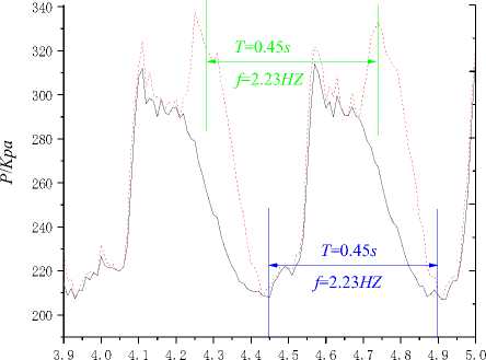
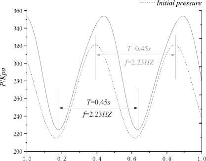
Figure 6. The relationship between the experimental pressure curve a) and the fitted pressure curve b) over time when f = 2.23HZ.
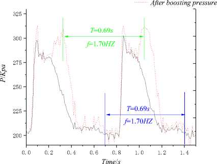
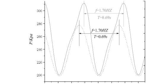
Figure 5. The relationship between the experimental pressure curve a) and the fitted pressure curve b) over time when f = 1.70HZ.
After boosting pressure
Time / s
b)
When the flow rate G1 in the pulsation system is constant, the relationship between the pulsation frequencies f3>f2>f1 and pressure changes is shown in Figures 3-5. As the pulsation frequency increases, the pressure generated by the diaphragm booster increases. The valve of the pulsation valve is driven by the motor to rotate the cam mechanism to control the opening and closing of the valve to generate a pulsating flow. As the frequency of the motor increases, the valve closing time is reduced [14]. Is due to the effect of pressure increase, which is the water hammer pressure. The pressure of the hydraulic shock in the pipeline increases as the valve closing time decreases, and the valve closing time is controlled by the motor frequency. Therefore, increasing the frequency of the motor means that the pipeline can produce a higher hydraulic shock. When the valve in the pipeline is momentarily closed, the moving fluid will produce a reverse shock wave. The pressure of the shock wave will cause the elastic diaphragm of the diaphragm supercharger to deform to promote the circulation of fluid in the pipeline connected to the outlet of the diaphragm supercharger [15]. When the fluid in the diaphragm booster system flows through the standard orifice plate, the flow rate increases, and the greater the impact pressure, the greater the acceleration of the fluid. When the accelerated fluid returns to the diaphragm booster, the elastic diaphragm will The high impact pressure acts on the pulsating fluid in the pipeline connected at the inlet of the diaphragm booster, thereby increasing the pressure of the pulsating fluid. As shown in Fig. 6, when the pulsation frequency f3>f2>f1, the change in pressure difference caused by the fluid acceleration in the diaphragm booster has AP3>AP2>AP1.
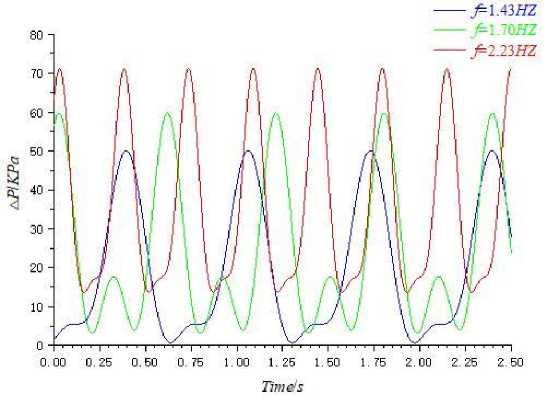
Figure 7. Relationship between pressure difference and frequency f at the same flow.
Conclusion
The analysis of the literature on the issue of increasing the energy efficiency of the membrane supercharger, in order to determine the relevance of the study. As a result of the analysis of the literature on the design, calculation, operation of diaphragm pumps with different types of drives, as well as pulsed heating systems, the idea of using pulsed coolant flow with acceleration in the circuit of a diaphragm pump to drive it was obtained.
The diaphragm booster device developed based on the principle of hydraulic shock is feasible. The device improves the heat exchange efficiency of the system through the conversion of the fluid's own energy, saving the energy consumption of the engine cooling system. Increased pressure.
References Study on the effect of diaphragm booster on the pulsed heat transfer of cooling system
- Timité B., Castelain C., Peerhossaini H. Pulsatile viscous flow in a curved pipe: Effects of pulsation on the development of secondary flow // International Journal of Heat and Fluid Flow. 2010. V. 31. №5. P. 879-896. DOI: 10.1016/j.ijheatfluidflow.2010.04.004
- Zhuang N. et al. Flow resistance of low-frequency pulsatile turbulent flow in mini-channels // International Journal of Heat and Fluid Flow. 2017. V. 65. P. 21-32. DOI: 10.1016/j.ijheatfluidflow.2017.03.005
- Yuan H., Ding Y., Li R. Experimental research on enhanced heat transfer based on pulsating flow of marine plate heat exchanger // Energy Conservation Technology. 2017. V. 35. №05. P. 433-437.
- Макеев А. Н. Импульсная система теплоснабжения общественного здания: дисс.. канд. техн. наук. Саранск, 2010. 153 с.
- Zhang D. et al. The Research Progress of Heat Transfer Enhancement of Pulsating Flow in Tube // Energy Conservation Technology. 2016. №3. P. 7.
- Овсепян В. М. Гидравлический таран и таранные установки. М.: Машиностроение, 1968.
- Hemida H. N. et al. Theoretical analysis of heat transfer in laminar pulsating flow // International journal of heat and mass transfer. 2002. V. 45. №8. P. 1767-1780.
- DOI: 10.1016/S0017-9310(01)00274-5
- Peng L., Qu D., Xu W., Chen J. Study on the closure of ball valve based on water hammer protection // Vibration and Shock. 2018. V. 37. №21. P. 41-45.
- Valencia A. Effect of pulsating inlet on the turbulent flow and heat transfer past a backward-facing step // International communications in heat and mass transfer. 1997. V. 24. №7. P. 1009-1018.
- DOI: 10.1016/S0735-1933(97)00086-9
- Огл Дж. В., Энгель А. Д. Влияние вибрации на двухтрубный теплообменник // Химическая инженерия. 1965. Т. 61. №5. P. 118-122.
- Попов Д. Н. Нестационарные гидромеханические процессы. М.: Машиностроение, 1982.
- Вест Ф., Тейлор А. Влияние пульсаций на теплообмен // Химическая инженерия. 1952. Т. 48. №1. С. 39-43.
- He Y.-L., Yang W., Zhao C.-F., Tao W.-Q. Numerical study of enhancing heat transfer by pulsating flow // Journal of Engineering Thermophysics. 2005. V. 3. P. 495-497.
- Karamercan O. E., Gainer J. L. The effect of pulsations on heat transfer // Industrial & Engineering Chemistry Fundamentals. 1979. V. 18. №1. P. 11-15.
- DOI: 10.1021/i160069a003
- Lemlich R. Vibration and pulsation boost heat transfer // Chem. Eng. 1961. V. 68. №10. P. 171-176.
