Studying static stability of a model rocket
Автор: Bordachev V.A., Kolga V.V., Rozhkova E.A.
Журнал: Siberian Aerospace Journal @vestnik-sibsau-en
Рубрика: Aviation and spacecraft engineering
Статья в выпуске: 1 vol.24, 2023 года.
Бесплатный доступ
Relevance. When designing flying models of rockets, one of the difficult tasks is to ensure the static stability of the rocket in flight along a given trajectory. Static stability refers to the ability of a model to return to an equilibrium position disturbed by external forces (wind, model asymmetry, etc.). In this case, the model must be stabilized in terms of the angle between the longitudinal axis of the model and the direction of flight (velocity vector), that is to maintain a zero angle of attack. The condition for ensuring the static stability of the rocket model is the location of its center of gravity ahead of the center of pressure. In this case, when the angle of attack is different from zero, the aerodynamic forces will create a stabilizing moment, which will return the model to a zero angle of attack. The purpose of the study is to develop and compare methods for determining the position of the center of pressure of a rocket and determining its static stability. The research considers a simplified method, an analytical calculation, a graphical method, and various practical approaches that can be used in rocket modeling. As research methods, an analytical approach, a graphical method and finite element modeling in the SolidWorks Flow Simulation program were used. In addition, a number of approximate calculation methods were considered. The study analyzes the capabilities of the considered methods for determining the static stability of a model rocket and the error of their application. To confirm the results of the calculation, a computer experiment was carried out in the form of blowing a finite element model of a rocket using the SolidWorks Flow Simulation program. The results of computer simulation confirmed the reliability of the proposed methods for determining the static stability of a model rocket. Research results. Simplified methods for determining the static stability of a rocket are the simplest and most reliable when designing model rockets. It is advisable to use it for launching demonstration rockets with an allowable misalignment error of 15% or more. Analytical methods are useful for designing sports models of rockets with high flight requirements, for example, for international competitions. Conclusion. The proposed method for ensuring the static stability of a model rocket makes it possible to simplify the design process of both demonstration and sports models of rockets for reliable demonstration launches.
Model rocket, center of pressure, static stability of the rocket, rocket design, stabilizers
Короткий адрес: https://sciup.org/148329674
IDR: 148329674 | УДК: 629.7.022 | DOI: 10.31772/2712-8970-2023-24-1-64-75
Текст научной статьи Studying static stability of a model rocket
A flying rocket model is driven by a model rocket engine (MRE) and rises into the air without aerodynamic lift of the supporting surfaces (like an airplane). At the same time, the model rocket has a rescue system for its safe return to the ground. In rocket modeling, unguided rocket models are used rising to height of 150–250 m, provided their static stability is maintained during the flight.
A single-stage rocket model (Fig. 1) consists of conical 1 and transitional 2 parts of the fairing, the body of the rocket model 3 and fins - stabilizers 5.
Equipment of the rocket model: rocket engine 10, rescue system parachute 8, wad 9 and two guide rings.
The conical and cylindrical parts of the fairing are made of drawing paper. The workpiece is wound on a mandrel 4 and glued. The conical part of the fairing is made in a similar way. It should be noted that the diameter of the adapter has to be slightly smaller than the diameter of the case so that it can be freely put on and taken off. This ensures free ejection parachute rescue system.
Model rocket stabilizers moving the center of pressure closer to the tail of the rocket are four plates cut out of durable cardboard 1–2 mm thick.
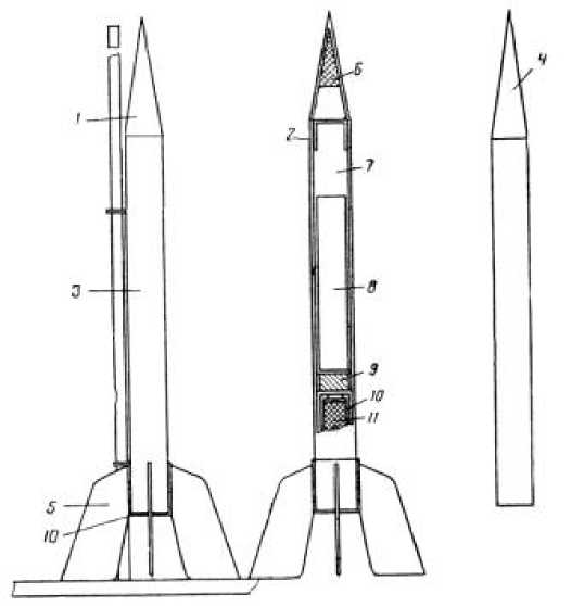
Рис. 1. Модель одноступенчатой ракеты:
1 – конусная часть головного обтекателя; 2 – переходник головного обтекателя;
3 – корпус модели ракеты; 4 – оправка; 5 – стабилизатор; 6 – полезный груз; 7 – стропы парашюта; 8 – парашют; 9 – пыж; 10 – микро-РДТТ; 11 – пороховая шашка микро РДТТ
-
Fig. 1. Model of a single-stage rocket:
-
1 – conical part of the head fairing; 2 – head fairing adapter; 3 – rocket model body;
-
4 – mandrel; 5 – stabilizer; 6 – payload; 7 – parachute lines; 8 – parachute; 9 – wad;
10 – micro-SPRE; 11 – powder checker micro solid propellant rocket engine
Three forces have got an impact on a rocket in flight: engine thrust (R), aerodynamic drag (P), and gravity (G) (Fig. 2). The thrust force of the engine is directed along the longitudinal axis of the model; gravity acts vertically downward and is applied at the center of gravity (c. g.); the aerodynamic force is opposite to the oncoming flow and is applied at the center of pressure (c. p).The center of pressure is the point of application of the resultant of all aerodynamic forces to the rocket body [1–5].
When designing flying models of rockets, one of the complex tasks is to ensure the static stability of a rocket in flight along a given trajectory [6–9]. Stability refers to the ability of a model to return to an equilibrium position disturbed by external forces (wind, model asymmetry, others). In this case, the model should be stabilized due to the angle between the longitudinal axis of the model and the direction of flight (velocity vector). The condition to ensure the static stability of the rocket model is the location of its center of gravity ahead of the center of pressure. In this case, when the angle of attack is not equal to zero, the aerodynamic forces will create a stabilizing moment, which will return the model to a zero angle of attack [10; 11].
Fig. 2 demonstrates two cases of the behavior of a rocket model during its movement along a vertical trajectory. The angle of attack is zero; the axis of the model coincides with the direction of flight. Under ideal conditions (in the absence of external interference), such a trajectory is maintained throughout the flight. In reality, it is almost impossible to reach. External forces (wind, unstable engine thrust) introduce errors into the flight path due to the angle of attack is not equal to zero. If the model is statically stable (Fig. 2, a), it will return to zero angle of attack. An unstable rocket (Fig. 2, b) will further increase the angle of attack and deviate more from the original vertical trajectory.
Analyzing the existing methods to ensure the static stability of a model rocket
One of the most common ways to ensure the static stability of a rocket model is aerodynamic. It consists of installing special surfaces - stabilizers - on the rocket body.
We could consider the conditions of aerodynamic stability in details. It depends on the relative position of the center of gravity (c. g.) and the center of pressure (c. p.) (Fig. 3).
If c. g. is located in front of c. p (Fig. 3, a), when the angle of attack appears, the aerodynamic forces will create a stabilizing moment, which will return the model to its
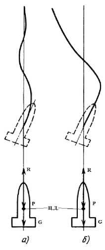
Рис. 2. Траектория полета модели ракеты: а – устойчивый полет;
б – неустойчивый полет
Fig. 2. Flight trajectory of the rocket model: a – stable flight; b – unstable flight
original state with a zero angle of attack. This model will be statically stable. The further displaced c.
g. relative to c. p. (counting from the head), the greater the margin of static stability the rocket model has got.
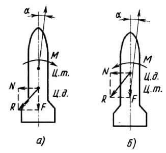
Рис. 3. Влияние взаимного расположения центра тяжести (ц. т.) и центра давления (ц. д.) на устойчивость модели в полете: а – модель устойчива; б – модель неустойчива
Fig. 3. Influence of the relative position of the center of gravity (c.g.) and the center of pressure (c. p.) on the stability of the model in flight: a – the model is stable; b – the model is unstable
If c. g. of the model is located behind c. p. (Fig. 3, b), thus, the aerodynamic forces arising as a result of a change in the angle of attack under the action of perturbing external forces will create a destabilizing moment that will increase this angle. This model will be unstable.
The ratio of the distance from c. g. to c. p. to the length of the rocket (at the origin at the head of the rocket) is called the static stability margin. For models with stabilizers, it should be 10-20%.
In practice, for model rockets, the center of pressure is shifted as close as possible to the engine compartment by increasing the total area of the stabilizers and installing them as far as possible from the head. In this case, the center of gravity is shifted to the head fairing due to the installation of an additional payload in the head part. The calculation of the static stability of a rocket, as a rule, is not specially carried out. Either traditional rocket models are used, which have already confirmed their static stability, or static stability is provided by test launches in the process of designing an experimental model.
Methods for calculating the static stability of a model rocket
The condition ensuring the static stability of the rocket model is the location of its center of gravity ahead of the center of pressure. s a rule, reference books on the strength of materials or calculation programs (SolidWorks, Ansys) are used to determine the geometric and mass characteristics of a structure [12]. However, the center of gravity of a model rocket can be easily determined by balancing it on the edge of a thin ruler. There are several techniques to find the center of pressure. As a rule, they are divided into calculated and practical ones [13–15].
Calculation method to determine the center of pressure
Approximate determination of the center of pressure according to the model drawing (on a flat figure)
The perturbations acting on the rocket model in flight are not great. The angle of deflection of the rocket changes slightly, as a rule, up to 15–20°. At low angles of attack, the position of c. p. deviates from the calculated. But when designing, it is possible to use an approximate method to determine the center of pressure in a symmetrical flow (at a zero angle of attack α = 0). The position of c. p. in this case will correspond to the position of the center of gravity of the flat figure of the model.
We could divide the model into a number of simple figures and find the coordinates of the total static moment (Fig. 4).
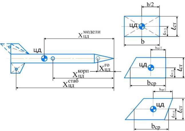
Рис. 4. Центр тяжести и центр давления модели и ее части
Fig.4. Center of gravity and center of pressure of the model and its parts го го корп корп стаб стаб
X мдд = —цдцд— ,
where S го - fairing projection area; S корп - model body projection area; S стаб - projection area of all stabilizers; S мод - sum of all areas; X го - ordinate of c. p. of fairing; X корп - ordinate of c. p. of body model; X стаб - ordinate of c. p. of stabilizers.
If X мод - X мод = С is a positive number, this means that the model will be stable, where C is the stability margin of the rocket model. The more C, the more stable the flight is.
To increase the stability margin C , it is necessary to increase the area of the stabilizers or change their location to a more “rear” one (to shift the position of the c. p. closer to the tail compartment). To ensure a more anterior location of c. g., it is possible to increase the mass of the head fairing.
Graphical method to determine the center of pressure of a rocket model
The position of the center of pressure depends on the elongation of the body of the model
λ= корпуса . For a rocket model with a cylindrical body without fin and a conical (or closer to a cone) dмиделя nose fairing, the position c. p. on the model axis can be found from the graph (Fig. 5). Knowing the position of c. g. and c. p. of the unfinned rocket body, we could set the stability margin С (С = 30, С = 20, С = 10) and according to the graph we find the coefficient of influence of the stabilizers proposed by the authors, knowing this, we can calculate the area of one stabilizer fin for the 4-stabilizer model (Fig. 6) :
S ст = 0,8 ⋅ К ст ⋅ d м 2 ид. .
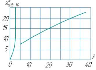
Рис. 5. График зависимости положения центра давления корпуса без стабилизаторов от его удлинения
Fig. 5. Graph of the dependence of the position of the center of pressure of the body without stabilizers on its elongation
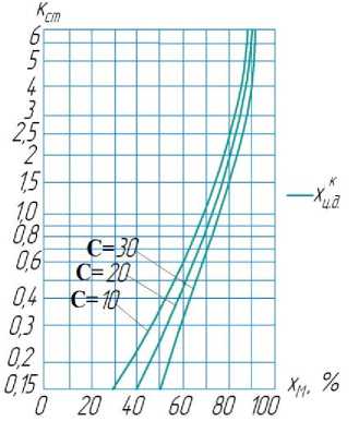
Рис. 6. График определения площади стабилизатора модели ракеты с четырьмя стабилизаторами
Fig. 6. Graph for determining the stabilizer area of a rocket model with four stabilizers
Analytical method to determine the position of the center of pressure according to the drawing model
A rocket model consists, as a rule, not only of cylindrical parts, but also of a number of conical ones. The graphic-analytical method does not take this into account, and a normal aerodynamic force acts on each of these parts. Knowing its magnitude and point of application, it is easy to find the total aerodynamic force R as the sum of individual forces and its coordinate Х у _ Rro ■ Хго + R ■ Х1 - RK ■ Хк + R2 ■ Х2 + RCT ■ Хст
Хц . д . =
R
where R o, R , R , R2 и RCT - aerodynamic forces acting respectively on the head fairing, the first cylindrical part of the model, the conical, the second cylindrical part and the stabilizers of the model.
Since the aerodynamic force depends on the flight speed, it is better to determine not the forces themselves, but their dimensionless coefficients C . In this case, the formula can look like this:
Х ц.д.
C R
го X
го
+ C R
1 X 1
—
C R kXk
+ C R
; 2 2 X 2
+ C R
ст X ст
C R
while CR = CR + CR — CR, + C„ + CR R R го R 1 R k R 2 R ст
It is assumed in the calculation, a cylindrical body at small angles of attack does not create lift, thus, the aerodynamic force coefficient of a cylindrical body is close to zero. The calculation determines the aerodynamic performance for the head fairing, conical adapter and stabilizers. It should be taken into account that the presence of a cylindrical body affects the airflow near the root chords of the stabilizers.
Two types of head fairings are common: conical and ogive. For both types, the aerodynamic force coefficient is the same: C„ = 2.
R го
For a conical head fairing, the center of pressure is located at a distance Х point, and for the ogive Х ц.д.
=---- L„ , where
2,15 го,
lro — fairing length.
=- R , its nasal
3 го
The conical adapter can increase or decrease the diameter of the model. The coefficient of aerodynamic force for the conical adapter is calculated by the formula
CRk = 2


where d 1 — lower diameter of the truncated cone; d 2 — upper diameter of the truncated cone; d — head fairing diameter.
For a tapering cone, this coefficient will turn out to be negative. This means the force Rк is directed against other forces and bodies differing in the aft part will have an unequal position of the center of pressure.
The position of the center of pressure of the cone is calculated by the formula
1 —
d 2
Xk = iP + - kp 3
1 +
d 1
1—
d 2 d
where lp — distance from the nose point of the model to the cone; lk — cone height.
Complex shape stabilizers can be represented as the sum of simple shape stabilizers, and their center of pressure can be determined from the average aerodynamic chord of the stabilizer fin. The aerodynamic force coefficient depends on the number of stabilizing surfaces. For a stabilizer with n surfaces, the aerodynamic force coefficient is calculated by the formula
C * R ст
N • ( l *т / d ) 2
2-1 I 1 ср
Ко корн + Ь конц у
where l * - stabilizer fin span; l - span along the midline. The coefficient N depends on the number of stabilizers.
The aerodynamic interaction of the stabilizers and the body of the rocket model is taken into account by the coefficient
r
Kp = 1+ П ср where r – model aft radius.
Therefore, the coefficient of aerodynamic force for the entire aft part of the rocket model is equal to
*
Cr = Kn ’ Cr •
R ст p R ст
The position of the center of pressure of the stabilizer depends on the shape of the stabilizer in plan and its location on the rocket body:
X k
= L +
A l ( b корн + 2 Ь конц ) Ь корн + Ь конц
+ -
( Ь корн
k
+ Ь конц
—
корн конц
> +b корн конц у
where L - distance from the nose point of the model to the root chord of the stabilizers; A l - the distance between the beginning of the root and end chords of the stabilizer.
A practical method to determine the center of pressure
The first method. From plywood, cardboard or other sheet material, a figure is cut out along the contour of the rocket model and c. g. is found for this flat figure. This point will be the required c. p. of the model [2] (Fig. 7). For a real model rocket, made according to the presented contour, the true position of c. g. is determined due to the weight of the head, the mass of the engine, the rescue system, others. The static stability margin of the rocket is also determined by the formula X М^д — X ММд = С .
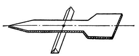
Рис. 7. Практический метод определения ц. д. плоской фигуры модели ракеты
Fig. 7. A practical method for determining c. p. a for flat figure model of a rocket
The second method – is a test of a rocket for stability using a wind tunnel. For this, the model is fully equipped: they put the engine, rescue system, wads, and other equipment. Further, the rocket is placed in the air stream towards the movement. The most uniform flow is created in a wind tunnel, the speed of which is at least 20–30 km/h. We could shift the rocket with a finger about 10º from the downstream position. If the model returns to its original position, then the static stability of the rocket is ensured (Fig. 8).

Рис. 8. Испытания модельной ракеты в потоке воздуха, выходящего из сопла аэродинамической трубы:
1 – модельная ракета; 2 – нить; 3 – аэродинамическая труба
Fig. 8. Tests of a Model Rocket in the Air Flow Out of the Wind Tunnel Nozzle: 1 – model rocket; 2 – thread; 3 – wind tunnel
In flight, as the fuel burns out in the engine, the position of c. g. of a model also changes. Almost all models has got the engine in the tail (stern) section. When the fuel burns, the mass of the rocket will decrease, and c. g. will move closer to the head, thereby, increasing the static stability of the model.
There are several ways to correct the stability of a model rocket. One of them is the displacement of c. p. to the stern by increasing the area of the stabilizers and their location. However, this is almost impossible to do on a finished rocket. Therefore, it is necessary to take into account possible options in advance (during its design): expand the aft part, choose the lower placement of stabilizers (behind the engine nozzle cut), increase the payload mass in the head fairing.
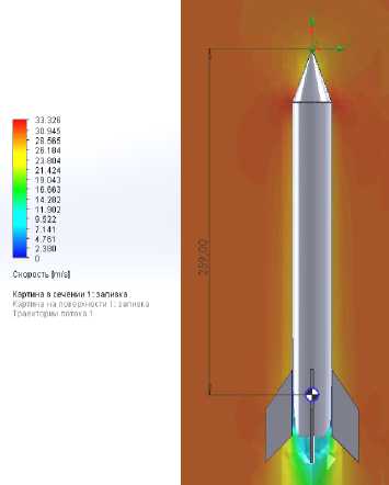
Рис. 9. Продувка модели ракеты с трапециевидными стабилизаторами в программе SolidWorks Flow Simulation
Fig.9. Purge model of a rocket with trapezoidal stabilizers in SolidWorks Flow Simulation
Comparison of methods for determining c. p. of a model rocket and determination of error
To determine the error of the described methods, we use three single-stage rockets with different types of stabilizers (Fig. 4)
We could note that the graphical method determines the area of the stabilizers with a known center of gravity of the rocket and the margin of static stability of the model.
Therefore, to find the position of c. p. we could use the opposite way, knowing the area of the stabilizers and c. p. of the unfinned body, we find the coefficient of influence of the stabilizers К ст and the true position of c. p. of models. We could put these values into the table.
For practical definition of c. p. of a model rocket by blowing, we use the SolidWorks Flow Simulation program (Fig. 9).
Error in determining the center of pressure of a rocket model for stabilizers of various types
|
Ь/2 ^К^з^ , ь |
Method to determine c. p. |
Coordinate of c. p, mm |
Absolute error, mm |
Relative error, % |
|
Calculated |
On «flat figure» |
177 |
45 |
15,52 |
|
Graphical |
252–258 |
30–36 |
10–12 |
|
|
Analytical |
223 |
1 |
0,34 |
|
|
Practical |
On «flat figure» |
178 |
44 |
15,17 |
|
Blowing |
222 |
– |
– |
|
|
/цд® |
||||
|
Calculated |
On «flat figure» |
173 |
46 |
15,86 |
|
Graphical |
249–252 |
30–33 |
10–11 |
|
|
Analytical |
220 |
1 |
0,34 |
|
|
Practical |
On «flat figure» |
173 |
46 |
15,86 |
|
Blowing |
219 |
– |
– |
|
|
Z__ /Г! |
||||
|
Calculated |
On «flat figure» |
177 |
82 |
28,28 |
|
Graphical |
243–249 |
16–10 |
6–3 |
|
|
Analytical |
259 |
0 |
0,00 |
|
|
Practical |
On «flat figure» |
179 |
80 |
27,59 |
|
Blowing |
259 |
– |
– |
Conclusion
Determining the center of pressure on a flat figure is the simplest and most reliable technique. It is advisable to use it for demonstration rockets with an allowable misalignment error of 15% or more. Analytical methods are appropriate for designing sports models of rockets with high flight requirements, for example, for international competitions, record flights.
The proposed technique to ensure the static stability of a model rocket makes it possible to simplify the design process of both demonstration and sports models for risk-free demonstration launches.
Список литературы Studying static stability of a model rocket
- Belonovskaya I. D. Kolga V. V., Yarkov I. S., Yarkova E. A. [Parametric analysis of the anisogrid body of a spacecraft for cleaning the orbit from space debris]. Sibirskiy aerokosmicheskiy zhurnal. 2021, Vol. 22, No. 1, P. 94–105. DOI: 10.31772/2712-8970-2021-22-1-94-105 (In Russ.).
- Bordachev V. A., Kolga, V. V., Rozhkova E. A. [Method for determining the position of the center of pressure of a model rocket]. Мaterialy XXVI Mezhdunar. nauch. konf. “Reshetnevskie chteniya” [Materials XXVI Intern. Scientific. Conf “Reshetnev reading”]. Part 1, Krasnoyarsk, SibGU, 2022. P. 15–17 (In Russ.).
- Kaltyga S. V., Kolga V. V., Terekhin N. A. Proyektirovaniye model'noy rakety s raketnym dvigatelem na tverdom toplive [Designing a Model Rocket with a Solid-Fuel Rocket Engine] Krasnoyarsk, SibGU, 2022, 97 p.
- Testoedov N. A., Kolga V. V., Semenova L. A. Proyektirovaniye i konstruirovaniye ballisticheskikh raket i raket nositeley [Design and construction of ballistic missiles and launch vehicles]. Krasnoyarsk, SibGAU, 2014, 308 p.
- Kolga V. V. Opredeleniye osnovnykh proyektno-konstruktivnykh parametrov i massovykh kharakteristik pri proyektirovanii raket [Determination of the main design parameters and mass characteristics in the design of missiles] Krasnoyarsk, SibGU, 2021, 112 p.
- Bordachev V. A. [Development of a scheme for attaching an orbital ship to a launch vehicle]. Мaterialy VII Mezhdunar. nauch. konf. “Aktual'nyye problemy aviatsii i kosmonavtiki” [Materials of the VII International scientific and practical conference “Actual problems of aviation and cosmonautics”]. Part 1, Krasnoyarsk, SibGU, 2021, P. 75–77(In Russ.).
- Kargopolov D. D., Kolga V. V. [Development of an air launch system for rockets] // Мaterialy VII Mezhdunar. nauch. konf. “Aktual'nyye problemy aviatsii i kosmonavtiki” [Materials of the VII International scientific and practical conference «Actual problems of aviation and cosmonautics”]. Part 1, Krasnoyarsk, SibGU, 2021, P. 90–93(In Russ.).
- Bordachev V. A., Kolga V. V. [Development of rocket plane structures]. Мaterialy XXV Mezhdunar. nauch. konf. “Reshetnevskie chteniya” [Materials XXV Intern. Scientific. Conf “Reshetnev reading”]. Part 1, Krasnoyarsk, SibGU, 2021, P. 13–14 (In Russ.).
- Bordachev V. A. [Design of fastening structures of a rocket plane to a launch vehicle]. Мaterialy XXV Mezhdunar. nauch. konf. “Reshetnevskie chteniya” [Materials XXV Intern. Scientific. Conf “Reshetnev reading”]. Part 1, Krasnoyarsk, SibGU, 2021, P. 15–16 (In Russ.).
- Davydik V. A., Kolga V. V., Ryazanova A. S. [Development of a method for separating the head part of a rocket model]. Мaterialy XXV Mezhdunar. nauch. konf. “Reshetnevskie chteniya” [Materials XXV Intern. Scientific. Conf “Reshetnev reading”]. Part 1, Krasnoyarsk, SibGU, 2021, P. 20–22 (In Russ.).
- Masich D. I., Kolga V. V. [The use of rotary parachutes when landing a descent vehicle]. Мaterialy VIII Mezhdunar. nauch. konf. “Aktual'nyye problemy aviatsii i kosmonavtiki” [Materials of the VIII International scientific and practical conference “Actual problems of aviation and cosmonautics”]. Part 1, Krasnoyarsk, SibGU, 2022, P. 88–90 (In Russ.).
- Kolga V. V., Marchuk M. E., Lykum A. I., Filipson G. Yu. [Optimization of the location of the attachment points of the instrument panel of the spacecraft based on modal analysis]. Sibirskiy aerokosmicheskiy zhurnal. 2021, Vol. 22, No. 2, P. 328–338. DOI: 10.31772/2712-8970-2021-22-2-328-338 (In Russ.).
- Rozhkov V. S. Kosmodrom na stole [Cosmodrome on the table] Moscow, Mashinostroenie Publ., 1999, 144 p.
- Elshtein P. Konstruktoru modeley raket [To the designer of rocket models] Moscow, Mir Publ., 1978, 320 p.
- Krotov I. V. Modeli raket: proyektirovaniye [Rocket models: design] Moscow, DOSAAF Publ., 1979, 176 p.

