Supercapacitor as a buffer electrical source for induction motor

Author: Saifulin Ruslan F.
Journal: Журнал Сибирского федерального университета. Серия: Техника и технологии @technologies-sfu
Section: Исследования. Проектирование. Опыт эксплуатации
Article in issue: 8 т.15, 2022.
Free access
Mathematical substitutions in the equations and the used methods have shown the adequacy and correctness of their use. Analysis of the data, obtained from simulation modeling of the developed model, showed small discrepancies with the standard block from the Simulink library. The use of the obtained mathematical equations, as well as the model assembled in Matlab Simulink, will make it possible to qualitatively evaluate the operation of an induction drive in statics and dynamics. This model will be used in future research, including the creation of a buffer power source based on a supercapacitor for an induction electric drive.
Electric drive, modeling, supercapacitor, math model, simulation
Short address: https://sciup.org/146282535
IDR: 146282535 | UDC: 621.131.332:621.319.4 | DOI: 10.17516/1999-494X-0431
Суперконденсатор как буферный источник электроэнергии для асинхронного двигателя
Математические замены в уравнениях и используемые методы показали адекватность и правильность их применения. Анализ данных, полученных при имитационном моделировании разработанной модели, показал небольшие расхождения со стандартным блоком из библиотеки Simulink. Полученные математические уравнения, а также модель, собранная в Matlab Simulink, позволят качественно оценить работу асинхронного привода в статике и динамике. Эта модель будет использована в дальнейших исследованиях, в том числе при создании буферного источника питания на основе суперконденсатора для асинхронного электропривода.
Text of the scientific article Supercapacitor as a buffer electrical source for induction motor
Цитирование: Сайфулин, Р. Ф. Суперконденсатор как буферный источник электроэнергии для аcинхронного двигателя / Р. Ф. Сайфулин // Журн. Сиб. федер. ун-та. Техника и технологии, 2022, 15(8). С. 940–947. DOI: 10.17516/1999-494X-0431
various ways of calculating this model. [2,3,4,5,6,7] However, these methods use vector multiplication, Euler transformations, and the substitutions that are made when calculating differential equations lead to a large number of terms in the equation. Therefore, this article proposes the calculation of the asynchronous motor model in a rotating coordinate system during the transition from a three-phase system to a two-phase one.
Mathematical calculation of the induction drive model
Initially, the induction drive is a three-phase electric machine with an implicit-pole rotor, it is proposed to simplify this model to a two-phase one. To simplify the mathematical description of induction drive, the space vector method turned out to be suitable. The method allows linking the rotor flux linkage equations into a single system with vector state variables. The essence of the method is that the instantaneous values of symmetric three-phase state variables (voltage, currents, flux linkage) can be mathematically transformed so that they are represented by one space vector. We represent a system of equations with vector state variables for the case with an arbitrary orientation of the coordinate system.
VT^T»
|
^rsTs+dl S +jaA |
(1.1) |
|
и dTR Vf R R R dt k m R |
(1.2) |
|
Ts=xs i s+X m iR |
(1.3) |
|
^ = xR i R+xm i S |
(1.4) |
|
m = kMod ( ^ i I k ) |
(1.5) |
|
dϑ m T m =mm c |
(1.6) |
Here US, UR, iS, iR, ΨS and ΨR are two-element vectors of voltages, currents and flux linkages, presented in an arbitrarily oriented orthogonal (two-phase) coordinate system in the form of components along the coordinate axes. The variable ωk is used to set an arbitrary frequency of rotation of the coordinate system. The auxiliary matrix constant j serves to “flip” the components of vector variables and simplifies the form of writing the system of equations. rS, rR – Resistance of stator and rotor, m- torque.
Expanding the content of space vectors, the flux linkage equations 1.3, 1.4 are substituted into the stator and rotor voltage formulas, while equating 1.2 to zero, since the electric motor is short-circuited.
"~* —*
U S =r S i S +
d(xsTs +X m :
dt
+ak ( xS^+x m^ R )
U R =r R i R +
d( x R i R +x m i S )
dt
+j ( a k -p& m )( X R i R +X m Ts ) =0
The change in the rotor current vector is expressed from equation 3
diR^ Tr^ x_mX . . xm^. !TR dt =-xRiR-xR dt- jαkiR-jαkxRiS+jpϑmxR
The rotor current vector is expressed from equation 1.4 and then substituted into equation 4
—> iR =
"TFT* ^ ΨR-xmiS
— xR
di R dt
rRXm^R Tr^S x2R + x2R
"> F^ FTP TFT xm diS xm ΨR xm ΨR
-jαk +jpϑm xR dt xR xR
Equations 5 and 6 are inserted into equation 2 to calculate the stator voltage vector
X s dTs _ r R X m У R
S S S dt x2R
rRx2miS xmdis xR dt +jpϑ
x2R
-
.mX- X m il+akc STS-jja k X m i S xR xR
The following replacements are introduced
2 r=r S +k R r R
(8.1)
x m kR=
'
xR x2m
(8.2)
x S =x S -xR
T R = X R r R
Let’s describe the vectors of stator and rotor voltages with introduced substitutions
(8.3)
(8.4)
x' di ⃗⃗ k ⃗ Ψ ⃗⃗⃗⃗ ⃗
⃗ U ⃗ ⃗ S =r S i ⃗ S ⃗ + + jα k x'Si ⃗ S ⃗ - +jpϑ m k R ⃗ Ψ ⃗⃗⃗⃗ R ⃗
⃗ Ψ ⃗⃗⃗ ⃗ ⃗ d ⃗ Ψ ⃗⃗⃗ ⃗ ⃗
⃗ U ⃗ ⃗ R =- k R r i ⃗ S ⃗ + R + R +j ( α k -p ϑ m ) ⃗ Ψ ⃗⃗⃗ ⃗ R ⃗ =0
R TR d t
In the case of coordinates orientation along the stator flux linkage, the moment can be expressed from equation 1.5 as m = ΨSαiSβ⃗ - ΨSβiSα⃗
In this case, the stator flux linkage vector from equation 1.3 is transformed by replacing the rotor current vector from equation 5
(⃗⃗⃗⃗⃗⃗-⃗
R m S)(12)
x R
And this equation 12 of the stator flux linkage vector can now be written along the axes, taking into account the replacements 8.1–8.4
⃗Ψ⃗⃗⃗S⃗⃗α⃗=x'Si⃗⃗S⃗⃗α⃗+kR⃗Ψ⃗⃗⃗R⃗⃗α⃗(13)
⃗Ψ⃗⃗⃗S⃗⃗β⃗=xSi⃗⃗S⃗⃗β⃗+kR⃗Ψ⃗⃗⃗R⃗⃗β⃗(14)
Accordingly, in the equation of moment 11, it is possible to replace the vectors of the stator flux linkage along the axes
' k R
( USy - akxS i Sx + tp ^ Ry-p ^ mkR ^ Rx )
r ( 1 + TS P )
And from equations 18.3, 18.4 the rotor flux linkage is expressed
T
Ψ R x = (k R r R i S x +(α k - pϑ m ) Ψ Ry R (21)
R x R R S x k m Ry 1+TRp
T
Ψ Ry = (k R r R i Sy - (α k - pϑ m ) Ψ R x R (22)
1+T R p
The speed from equation 18.6 will be
ϑ m = (m-m c )
Tmp
Thus, from the obtained final equations 19–23, a mathematical model of induction drive in a rotating coordinate system was created. At the same time, this model was transformed from a three-phase into a two-phase one – Fig. 1.
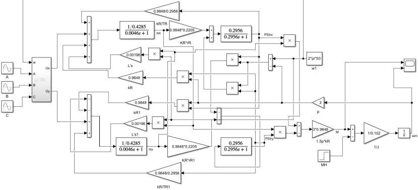
Fig. 1. Model assembled in Simulink
Imitation modeling
In this paper, a model of an AIR 160S 4 induction electric motor is considered with the following parameters presented in Table 1.
Table 1. AIR 160S 4 parameters
|
Motor |
Power, kW |
Speed, rpm |
Voltage, V |
Efficiency, % |
Power factor |
к In |
M M n |
max ——— M n |
Moment of inertia, kgm2 |
|
AIR 160S 4 |
15 |
1450 |
400 |
89.5 |
0.86 |
7,7 |
2.2 |
2.6 |
0.075 |
To assess the adequacy and correctness of the assembled model, it was proposed to compare it with the induction motor model from the standard Simulink/Simscape library – Fig.2.
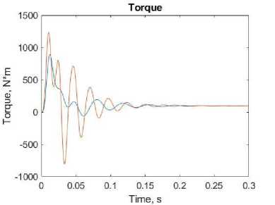
The rotor speed and the torque developed by the motors are shown in the Fig. 3 for the model in a rotating coordinate system – blue, and for the standard model – orange.
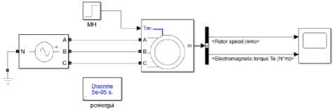
Fig. 2. Standard model of an induction motor in Simulink
Speed
о. 1000
о- 500 (Л
(a)
-500 L 0
0.05 0.1 0.15 0.2 0.25 0.3
Time, s
(b)
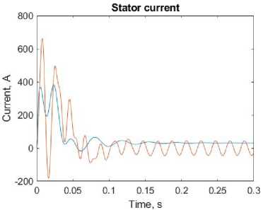
Fig. 3. Output characteristics of electric drives: a – speed, b – torque, c – stator current
(c)
From the obtained characteristics, it can be seen that the output values coincide, and the processes take place at the same time. However, the system from the standard library is more oscillatory, so the model in the rotating coordinate system has a better transient process. It is planned to compare these models with a real electric drive to obtain the most accurate results in further researches.
Conclusion
Mathematical substitutions in the equations and the used methods have shown the adequacy and correctness of their use. Analysis of the data, obtained from simulation modeling of the developed model, showed small discrepancies with the standard block from the Simulink library. The use of the obtained mathematical equations, as well as the model assembled in Matlab Simulink, will make it possible to qualitatively evaluate the operation of an induction drive in statics and dynamics. This model will be used in future research, including the creation of a buffer power source based on a supercapacitor for an induction electric drive.
References Supercapacitor as a buffer electrical source for induction motor
- Galiev E. A. Mathematical modeling of an induction motor with variable ir - ys. Yekaterinburg, 2017, 64.
- Schreiner R.T. AC drives based on direct frequency converters with PWM. Yekaterinburg, 2012, 222.
- Sokolovsky G.G. AC drives with frequency control. Moscow, 2006, 272.
- Petrushin V. S. Induction motors in a controlled electric drive. Odessa, 2006, 320.
- Kopylov I. P. Design of electrical machines. Moscow, 1980, 496.
- Klyuchev V. I. Theory of electric drive. Moscow, 0985, 560.
- Veinger A. M., Designing of electric drives. Sverdlovsk, 1980, 160.
- Dineva A. Mosavi A. Ardabili S. F. Review of soft computing models in design and control of rotating electrical machines. In: Energies, 2019, 12(6), 1049.
- Omar Faruque M. D., Strasser T., Lauss G. Real-time simulation technologies for power systems design, testing, and analysis. In: IEEE Power and Energy Technology Systems Journal, 2015, 2(2), 63-73.
- Wang L., Jatskevich J., Dinavahi V., Methods of interfacing rotating machine models in transient simulation programs. In: IEEE Transactions on Power Delivery, 2010, 25(2), 891-903.
- Delaleau E., Louis J. P., Ortega R. Modeling and control of induction motors. In: International Journal of Applied Mathematics and Computer Science, 2001, 11, 105-129.
- Pronin M., Shonin O., Vorontsov A., Gogolev G., Nahdi T. A Double-Fed Induction Machine with a Multistage-Multilevel Frequency Converter for Pumped Storage Power Plant Applications. Proceedings of IEEE Power Engineering and Automation Conference (PEAM), 2011, 1(1), 221.
