Технологические особенности контактной сварки пересекающихся стержней вкрест из алюминиевых сплавов

Автор: Бусыгин С.Л., Демченко А.И., Новосельцев Ю.Г., Безруких А.А., Шайхадинов А.А., Арямнова М.А.
Журнал: Журнал Сибирского федерального университета. Серия: Техника и технологии @technologies-sfu
Статья в выпуске: 6 т.9, 2016 года.
Бесплатный доступ
В статье описаны технология и технологические режимы контактной сварки стержней из алюминиевых сплавов вкрест. Исследована величина осадки стержней из сплава АД1. Получены зависимости для расчёта степени осадки двух пересекающихся стержней вкрест из алюминиевого сплава АД1. На практике подобраны режимы контактной сварки стержней из алюминиевого сплава АД1 диаметрами 4,3, 3,2, 2,5 мм. Построены циклограммы: изменяющегося усилия сжатия сварочных электродов и принудительного ограничения усилия сжатия сварочных электродов. Установлено, что принудительное ограничение осадки рельефа благоприятно влияет на прочность сварного соединения.
Контактная сварка, цикл сварки, осадка рельефа, аппроксимация, образование литого ядра
Короткий адрес: https://sciup.org/146115124
IDR: 146115124 | УДК: 621.791 | DOI: 10.17516/1999-494X-2016-9-6-905-911
Technological peculiarities of electric resistance welding of intеrsecting crosswise rods made of aluminum alloys
The technology and technological conditions of electric resistance welding in the shape of a cross of rods made of aluminum alloys are described in the article. “Technological peculiarities of electric resistance welding of interesting crosswise rods made of aluminium alloys”. The value of penetration of rods made of alloy AD1 was investigated. Dependences for calculations of the penetration degree of two intersecting cruciform rods made of an aluminum alloy AD1 was obtained. Welding conditions of electric resistance welding of rods made of an aluminum alloy AD1 with diameters 4,3 mm, 3,2 mm, 2,5 mm were selected in practice. Cyclical diagrams on the changing effort of welding electrodes compressing and a forced restriction of compression effort of welding electrodes were made. It was determined that forced restrictions of relief penetration(settling) infl uences perfectly the strength of the welding joint.
Текст научной статьи Технологические особенности контактной сварки пересекающихся стержней вкрест из алюминиевых сплавов
used e.g. AD1, penetration(settling) value of rods is greater but compound strength is less. Initial area of mutual contiguity of rods from a moment of compression to applying of welding current depends on, mainly, the electrodes pressure as well as on the kind of materials of welding rods. The higher pressure and softer rods material, the greater contiguity area.
In order to determine optimum compression effort Fw, dynamics of change of aluminum rods penetration values (distance between electrodes) for the compression time t comp =0,6 (cyclical diagram with constant welding effort was used). Main dependences values obtained are shown in Fig. 1. It is demonstrated in the diagram that rods settling (penetration) occurs even without welding current passage, here, the less rods diameter, the greater settling value (settling of rods made of an aluminium alloy AD1 with a diameter 2,5 mm occurs fully, if compression effort Fw=1 kH).
Curves oblained can be presented as follows [4]:
Δh(Fw)=k∙Fw+2d, (1)
where Δh – rods settling value, mm; F w – compression effort of welding electrodes, kH; K – coefficient, dependent on the rods diameter; d – rod diameter, mm.
Here, k has the following values (k 1 – 0,4; k 2 – 1; k 3 – 1,7). In the approximation the following dependence was obtained:
k(d)=2,4∙ln(d)-3,9, (2)
Final dependence is the following one:
Δh(Fw)=(2,4∙ln(d)-3,9)∙Fw+2d, (3)
Dependence obtained is true for calculation of settling values of two intersecting crosswise rods made of an aluminium alloy AD1.
Ivestigations of conditions of electric resistance welding were made by means of a machine MT2507. A cycle with constant effort and one impulse welding current were used, moreover, the time compression t comp and time forging t f was 0,04 S.
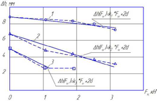
Fig. 1. Dependences of rods settling made of aluminum alloys AD 1: 1 – a rod of diameter 4,3 mm; 2 – a rod of diameter 3,2 mm; 3- a rod of diameter 2,5 mm
In welding of rods made of an aluminum alloy AD1 with a diameter 4,3 mm there were no great difficulties, optimum conditions – F w = 1,1 kH, I w = 12 kA, t w = 0,04 S. Changing welding time tw =(0,02 – 0,06)S, compound strength under elastic test was not changed, practically, the difference was 4-6%, however, settling value of rods A h increased from 6,8 to 4,8 mm accordingly. By increasing compression effort Fw, compound strength started decreasing sufficiently. In welding similar rods with a diameter 3,2 mm there were no great difficulties. In the process of investigation of electric resistance welding conditions of rods, diameter 2,5 mm, it was impossible to get a welding joint since a full penetration of welding rods occurred at welding time t w =0,02 S and at welding current I w =10 kA there wasn’t even a partial joining on the samples surfaces. By increasing welding current to I w = 12 kA a splashing out happened and by reducing compression time t w from 0,04 to 0,02 S there was also a splashing out, a welding joint wasn’t formed. Having increased the rods diameter to 3,2 mm relief specific strength increased and after welding there was a partial samples joining. However, in investigation of welding conditions, a qualitative joint was not obtained and it was determined that optimum conditions in this case were F w =1,1 kH, I w =12 kA, t w =0,02 S (t comp =0,04 and tf=0,04 S). In this case there was practically a complete penetration of relief, a tensile strength limit of the welding joint was ≈ 80% from a base metal. Reducing welding current to I w =10 kA, a welding joint isn’t formed.
The main difficulty of electric resistance welding of rods made of an alloy AD1 with a diameter-3,2 mm and less is the free displacement of the welding metal outside the welding joint; for compression time t w only relief penetration to a certain value depending on compression effort F w takes place, however, if welding current passes during tw and at the time tf maximum settling of the welding joint occurs, moreover, in most cases when welding current is turned off, settling (rods penetration) takes place without increase of cast core size.
Cyclical diagram with changing compression effort of welding electrodes is shown in Fig. 2.
The cyclical diagram acts in the following way:
-
– At the first stage, when preliminary compression t comp ; rods made of an aluminum alloy are compressed by effort Fw, here, increase of contact surfaces of parts occurs;
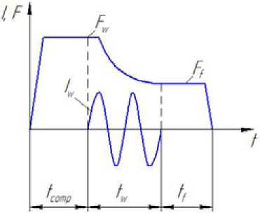
Fig. 2. Cyclical diagram with changing compression effort of welding electrodes: F w – compression effort of welding electrodes; F f – forging effort; I w – welding current; t comp – time of preliminary compression; t w – welding time; t f – forging time.
-
– At the second stage tw, when welding current is turned on, parts begin to heat sufficiently, fracture of a surface oxide film and formation of cast core occur, since a great effort resuts in a splash out. To suppress the initial impulse it’s necessary to reduce the effort smoothly with restriction of rods setlting (penetration);
-
– At the third stage tf a control unit withstands effort Ff automatically in order to eliminate stresses and increase of strength of the welding joint.
The application of this cyclical diagrams in the nets production requires expensive equipment, since in welding of nets automation lines are used, which work on the simple cycle with the constant compression effort of welding electrodes. Usage of the cyclical diagram allows to increase density of the welding joint to 2-5%.
In selection of optimum technology of electric resistance welding of interesting rods made of an aluminum alloy AD1, the task is set: simplicity and efficiency of technology offered and a low cost of reinstallation of applying equipment.
In this paper to reduce settling values of welding rods made of aluminum alloys AD1, diameter 3,2 mm, it is suggested to use a coercive restriction of relief setting for forging time – tf.
Welding procedure is carried out in the following way: electrodes are compressed t comp =0,04 S, welding current passes Iw, for the time tw=0,02 S, then electrodes are lowered to a given value H, in accordance with diameters of welding rods (for rods made of an aluminum alloy AD1, diameter 3,2 mm, 4,5 – 5 mm accordingly)the total thickness of rods after welding in the area of their intersection H, has the following dependence:
H(d)=5,5∙ln(2d)-5,3, (4)
where d – rods diameter, mm.
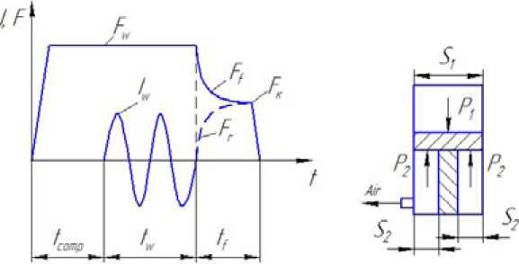
In this case the problem of relief setting in heated condition is solved, because a considerable part of cast core formation, occurs, mainly, by passing of welding current, but when it is turned off settling continues to the complete pressing in relief. Researches carried out show that the forced restriction of relief settling for forging time tf’, affects greatly the strength of a welding joint (Fig. 3).
Restriction of the compression effort of welding electrodes can be described by the following dependences:
-
– Pressure in aw upper chamber of a pneumatic cylinder P 1 :
P 1 =F w / S 1 , (5)
-
– Pressure in a low chamber of a pneumatic cylinder:
P 2 =F w – F f / S 1 , (6)
where F w – a compression effort of welding electrodes kH; S 1 – square of an upper chamber, mm; S2 – square of a low chamber of a pneumatic cylinder, mm; Fk – final compression effort of welding electrodes, kH.
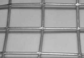
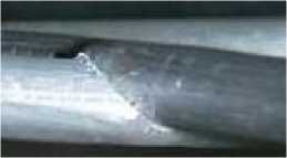
However, when welding procedure is set, it is necessary to see that at the moment of welding time t w settling of welding relief (process of cast core formation) occurs in a regular condition. Under insufficient settling value and increased welding time tw, the final splash out takes place [5]. In Fig. 4 joints of aluminum rods of nets made by electric resistance welding are shown.
a) b)
Fig. 3. Cyclical diagram with the forced restriction of a compression effort of welding electrodes: a) Welding cycle: F w – a compression effort of welding electrodes; F f – a forging effort; F r – an effort f forced restriction of relief setting; F k – final effort of welding electrodes compression; I w – welding current; t comp – preliminary compression time; t w – welding time; t f – forging time; b) Operation of a pneumatic cylinder of a resistance welder: P 1 – pressure in an upper chamber of a pneumatic cylinder; P 2 – pressure in the bottom chamber of a pneumatic cylinder; S 1 – square of an upper chamber of a pneumatic cylinder; S 2 – square of a low chamber of a pneumatic cylinder
a)
Fig. 4. Joints of aluminum rods of a net made by electrical resistance welding: a – General view of a joint to aluminum rods of the net; b – Enlarged view of a joint of aluminum rods of the net
b)
On the basis of results of the work the following conclusions can be drawn:
-
– The process of electric resistance welding of intersecting crosswise rods made of aluminum alloys differs considerably from the process of spot welding of sheet structures because more preferable conditions to get qualitative welding joints were created.
-
– Dependences of calculations of settling values of two intersecting crosswise rods made of an aluminum alloy AD1 were obtained.
-
– Electric resistance welding conditions of rods made of an aluminum alloy AD1 with diameters 4,3 mm, 3,2 mm, 2,5 mm were selected.
-
– Cyclical diagrams were drawn:
-
• On changing compression effort of welding electrodes;
-
• On forced restrictions of compression effort of welding electrodes.
– It was determined that forced restrictions of relief settling influences perfectly the strength of a welding joint.
Список литературы Технологические особенности контактной сварки пересекающихся стержней вкрест из алюминиевых сплавов
- Орлов Б.Д. Технология и оборудование контактной сварки. М.: Машиностроение, 1986. 352 с.
- Гилевич В.А. Технология и оборудование рельефной сварки. Л.: Машиностроение, 1976. 152 с.
- Рязанцев В.И., Овчинников В.В. Технологические основы контактной сварки легких сплавов. М.: МГИУ, 2006. 164 с.
- Пустыльник Е.И. Статистические методы анализа и обработки наблюдений. М.: Наука, 1968. 288 с.
- Демченко А.И., Pафальский А.С. Пpименение контактной точечной и pельефной сваpки пpи изготовлении теpмоэлементов автоматических выключателей. Журнал Сварочное производство, 2008, 8, 23-26
