Telemetry, command and ranging system of geo spacecraft

Author: Patyukov Viktor G., Ryabushkin Stanislav A., Shatrov Vitaly A.
Journal: Журнал Сибирского федерального университета. Серия: Техника и технологии @technologies-sfu
Article in issue: 7 т.7, 2014.
Free access
The article describes the telemetry, command and ranging system of GEO spacecraft. It addresses RF signals passage in ground-to-spacecraft path. Results of RF link budget calculations are presented. The article also addresses unaccountable parameters of using onboard and ground equipment having performances required by the link budget. System operation in ranging mode is described, as well as the existing problems of its usage. Prospects of existing disadvantages handling and system performance improvement were given.
Geo spacecrafts, tcr systems
Short address: https://sciup.org/146114903
IDR: 146114903 | UDC: 621.396.94
Система телеметрии, команд и дальности геостационарных космических аппаратов
В статье описана система телеметрии, команд и дальности геостационарных космических аппаратов. Рассмотрен проход радиочастотных сигналов по пути земля-КА. Представлены результаты расчета бюджета радиочастотной линии. Изложены необъяснимые параметры использования бортового и наземного оборудования, имеющего параметры, требуемые бюджетом линии связи. Описаны работа системы в режиме измерения дальности, а также существующие проблемы его применения. Даны перспективы существующих недостатков обработки и улучшения производительности системы.
Text of the scientific article Telemetry, command and ranging system of geo spacecraft
The spacecraft commanding system can be subdivided into two major components: onboard control subsystem and ground control segment (OCS and GCS). Data exchange between them is ensured by telemetry command and ranging system (TCR). TCR utilises a mission-specific RF link for data exchange between OCS and GCS (there are also scenarios of TCR operating via relay satellite).
TCRs possess a number of special features uncharacteristic of satellite telecommunications systems but significantly impacting their design:
-
1. TCR shall enable SC commanding in various flight modes: during SC positioning to its nominal orbital slot and in-orbit mission, in oriented and non-oriented SC attitude, in nominal operating conditions and in presence of contingencies and emergencies in the SC.
-
2. Sources of data transmitted on TCR links are located both onboard the SC and on the ground, whereas SC telecom payload is a mere repeater for signals coming from the ground stations.
-
3. TCR links shall simultaneously transmit data and do the ranging.
-
4. TCR shall ensure advanced validity for data sent to SC and enable mandatory acknowledgement of data passage, because sending of an unauthorised command (command transformation) or command omission can lead to serious and sometimes – irreversible consequences.
-
5. Amount of data transmitted on TCR RF links is relatively small.
-
6. In Russian practice, TCR systems interact with SC in sessions much shorter than intervals between them (this enables controlling multiple SC from one ground station).
Signals usd by tcr
Creation of combined TCR links requires solving a number of specific tasks related to selection of signal structure and processing method. All data handled by contemporary TCRs is digital. It simplifies processing and allows usage of the most noise-immune modulation and encoding methods.
Combined TCR links require multiplexing of various data types. Thus return link requires multiplexing of information coming from numerous telemetry sensors together with MLTC (memoryload telecommand) acknowledgements, at the same time maintaining a possibility for ranging. This is achievable, for example, with frequency division multiplexing and multi-modulation. For this purpose, telemetry sensors’ signals are first converted into digital form and then subjected to time multiplexing. The resultant digital stream STM, also referred to as TCR TM signal (in pulse-code modulation), is then used as frequency or phase modulating (shift keying) signal for a harmonic wave having frequency FTM. The same way, digital acknowledgement signals SACK and ranging signals SR are used to modulate (shift-key) their subcarriers of FACK and FR. In turn, the sum of signals on subcarriers modulates (shift-keys) the carrier wave f0 in phase or frequency. A signal made this way is defined as PCM-FM(PM)-PM(FM).
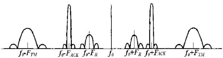
Fig. 1. TCR RF link signal spectrum
To perform high-accuracy RF measurements of velocity and distance, and to facilitate communication establishment in the resultant spectrum, it is preferable to have the essential component of the spectrum in carrier frequency. This is why the carrier is most commonly phase shit-keyed not at ± 90 ° but at ± 60 ° . An example of signal spectrum is shown in Fig. 1:
It is obvious that in such link the total power is divided between TM, acknowledgement, ranging and carrier signals. This results in signal-to-noise ratio reduction for each individual signal and, correspondingly, degradation of noise immunity.
Tcr rf link
-
F ig. 2 shows a diagram of TCR link energy levels.
In order to enable spacecraft control by means of TCR system, onboard and ground equipment development includes link budget calculation. The link consists of two parts: ground-SC and SC-ground. In energy aspect, both parts are critical, the first one – because of the temptation to Tx power minimisation and ground stations simplification, the second one – because of onboard equipment mass, dimension and power consumption constraints. The key feature of the link is high signal losses caused by signal attenuation in RF paths and by big distance. The ground-SC link, beside free space, also passes atmosphere which causes additional nonlinear distortions.
The key characteristics to be taken into account for calculation of a typical TCR uplink are listed below:
-
- ground antenna - 11 m;
-
- output power - 650W;
-
- EIRP - 83,03dBW;
-
- overall propagation losses - 201,89dB;
-
- pointing losses - 0,6dB;
-
- polarisation loss - 0,3dB;
-
- PFD on SC Rx antenna - 85,62 dBW/m2;
-
- losses in hardware paths - up to 4,5dB.
Provided the aforesaid performances, TCR stable operation is ensured.
Unaccountable peculiarities of signal propagation
The distance L between transmitting and receiving points is measured with a help of modulated signals by determining the time ∆t of radio waves propagation; herewith, it is assumed that
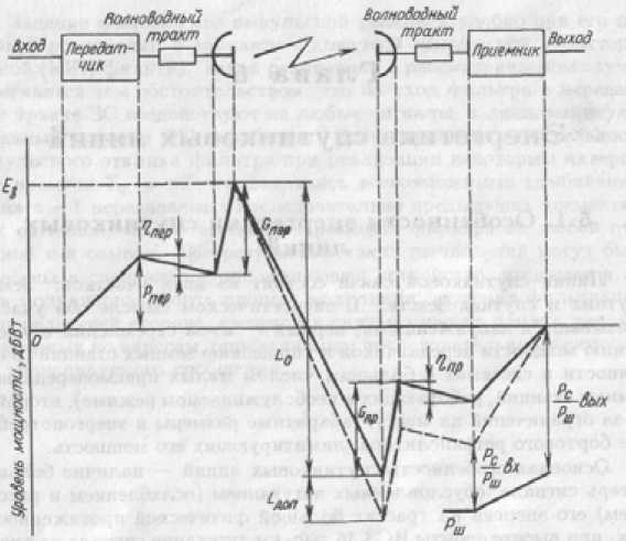
Fig. 2. Architecture and energy diagram of one SC communication link section
L = c 0 A t , (1) where c 0 is the speed of electromagnetic wave propagation in vacuum. As it is possible to measure the Δt interval with a very high precision, the distance L can be accurately determined; however, Earth’s atmosphere and ionosphere have a notable contribution to ranging errors. The reason is that the speed of RF waves propagation in atmosphere and ionosphere is different from c 0 and that beam lines get bent. Therefore, the true distance L 0 between transmitting and receiving points will be different from the measurement by Δ L , which is calculated as a sum of values ΔL t and ΔL i (troposphere-induced and ionosphere-induced errors) calculated as follows [1]:
N 0 b 1 cos2 θ b
A L,- = X f - 2 I e cos - 1 6 m ,
H
ALt = cos-1 6b J N(h)dh , ALt = where N0 is the reduced near-surface refraction factor, b1 is the refraction factor (variable within 0,12 to 0,14 km-1), χ = 40,4 is a constant for ionosphere refraction factor calculation applicable if electron density Ne(h) is measured in m3, h is the altitude over the surface of Earth, f is signal frequency, θb
H is beam line zenith angle at Earth surface, Ie = J Ne (h)dh is integral electron density, 9m is beam line zenith angle in ionosphere primary maximum. 0
Calculations of ΔL for TCR RF link show small values, but in satellite slant range measurements requiring an accuracy of within ten metres, this value becomes significant.
When signal source or receiver move, a change of frequency occurs which is caused by Doppler effect. Doppler frequency shift Δf0 is determined by wavelength and projection of speed vector on the – 835 – line connecting the transmitter and receiving points. Atmospheric and ionosphere contributions cause an additional frequency shift Δf, therefore the total frequency shift Δfs is found as a sum:
A f s = A f о + A f , (4)
A f = V[ Nv 2 - ^ a V i (1 + N a )] (5)
where ξ A and N A are respectively refraction angle and reduced refraction factor in point A (SC location point), v 2 and v 1 are projections of SC speed vectors on the SC-ground line and its perpendicular, respectively, λ0 is wave length in vacuum.
Ranging mode
One of TCR’s main purposes is ranging (RNG) of the spacecraft (SC), which implies measuring the distance to SC. The time method of ranging with a continuous signal is only possible when a baseband signal is used as the message-bearing one. This may be a broadband signal in a noise or pseudonoise form (usually, RNG uses pseudonoise signals which shift-key the carrier). In another case, the distance is determined by phase method. GCS measures the instantaneous difference in phases of signal generated by the station itself and the one returned by the SC. Knowing the measured phase shift and the frequency of processed signal, it is possible to calculate signal propagation time and, correspondingly, distance.
There is a need for measuring the SC range with a great precision, for example, in satellite navigation, the requirements for ground-to-SC and SC-to-SC distance measurement accuracy are constantly growing.
In control operations of telecommunications SC using European standards, the ranging function is implemented with several baseband tones (frequencies). The highest tone (major tone) ensures measurement accuracy, whereas the rest of tones are needed for ambiguity solution [1, 2]:
Major tone: ≈ 100 kHz
Minor tones: ≈ 27 kHz
4 kHz
283 Hz
35 Hz
Phase shift measurement includes summing of the following delays:
-
- Transmitting path delay in “GCS hardware – antenna feed input coupler” section;
-
- Transmitting path delay in “coupler – reflector aperture plane” section;
-
- Time of signal propagation in “GCS antenna – SC antenna” section;
-
- TCR onboard hardware delay;
-
- Time of signal propagation in “SC antenna – GCS antenna” section;
-
- Delay in “reflector aperture plane – LNA input” section;
-
- Receiving path delay in “LNA input – GCS hardware” section.
Phase shift measurement includes summing of the following delays:
-
- Transmitting path delay in “GCS hardware – antenna feed input coupler” section;
-
- Transmitting path delay in “coupler – reflector aperture plane” section;
-
- Time of signal propagation in “GCS antenna - SC antenna” section;
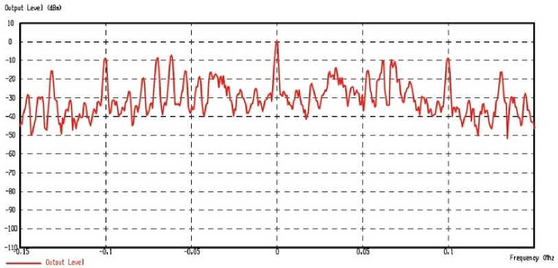
Fig. 3. Ranging signal spectrum
- TCR onboard hardware delay;
- Time of signal propagation in “SC antenna – GCS antenna” section;
- Delay in “reflector aperture plane – LNA input” section;
- Receiving path delay in “LNA input – GCS hardware” section.
6. Conclusion
SC ranging only requires measuring the time of signal propagation in space. The other delays are constant and their values are obtained during development and testing of space system, and in particular – onboard and ground measuring equipment.
Thus, total delay in ground and onboard hardware paths reaches several tens of milliseconds, and its measurement and calibration error does not exceed 50 nanoseconds, which theoretically makes it possible to measure the distance to SC with a 16-metre accuracy. Various aspects of delay measurement error reduction including the errors induced by the near-Earth wave propagation environment, and possibility of use of digital processing for received signals, were covered in articles [4, 5, 6].
The difficulty of ranging method implementation consists in correct adjustment of GCS equipment: it is required to accurately (not more than 50 ns total) measure the aforementioned delays in transmitting and receiving paths and in digital processing devices. As ranging signal’s bandwidth is >100kHz (see Fig. 3), there are some distortions in the duration of signal passage through the ground paths: roughly, different parts of signal experience different delays.
-
1. The following effects are often ignored in link budget calculations: RF waves, refraction and dispersion due to fluctuation and non-uniformity of troposphere and ionosphere; Doppler effect during SC launch; RF waves delay in troposphere and ionosphere; signal frequency shift under influence of troposphere and ionosphere.
-
2. System performances enhancement (data rate, command rate, RNG accuracy etc.) demands higher consumption of resources, which are strictly limited onboard the SC, and as for the ground control segment, higher resource allocation may result in exposure of some areas to antenna side lobes.
Another way of performances improvement is use of new technologies in equipment manufacturing or sophistication of mathematical apparatus by scientific and statistical data and experience, which is rather hard to achieve due to absence of hardware components and corresponding educational establishments in Russia.
Acknowledgment
Work is performed with financial support of the Ministry of Education and Science of the Russian Federation in the Siberian federal university (Contract No. 02.G25.31.0041).
