Test of the layout of the correction circuit with a plate heat exchanger

Author: Guo Zhengyang, Shan Jingwei, Li Jun, Levtsev Aleksei
Journal: Бюллетень науки и практики @bulletennauki
Section: Технические науки
Article in issue: 1 т.7, 2021.
Free access
Pulse enhanced heat transfer technology is introduced, and a plate heat exchanger is designed. A pulsating valve is installed at the outlet of the heat exchanger to pulsate the heat medium. Pulsating and non-pulsating heat transfer tests are carried out on the same heat exchanger. On the basis of experiments, the effective temperature difference, heat flow and convective heat transfer coefficient of the heat exchanger at different pulse frequencies are analyzed by combining the theory of pulse enhanced heat transfer technology, heat transfer capacity, heat flow and convective heat transfer coefficient. Find the relationship between pulsation frequency of heat transfer effect of heat exchanger. The experimental results show that the heat exchanger has high heat transfer efficiency under the experimental conditions when there is pulsation.
Pulsating generator, pulsating flow, frequency, heat transfer
Short address: https://sciup.org/14117934
IDR: 14117934 | UDC: 621.565.95 | DOI: 10.33619/2414-2948/62/28
Text of the scientific article Test of the layout of the correction circuit with a plate heat exchanger
Бюллетень науки и практики / Bulletin of Science and Practice
UDC 621.565.95
Research Background and Theoretical Research
With the vigorous development of modern industry and the continuous progress of science and technology, the demand for energy in human society is increasing [1]. In recent years, energy issues have become more and more of the global concern. In the field of energy utilization heat exchanger is the most common and important unit equipment, so it is very important to improve the heat transfer efficiency of heat exchanger. Enhanced heat transfer technology is a technology developed in 1960s to improve heat transfer performance. The application of enhanced heat transfer technology not only saves energy and environmental protection [2] but also saves investment and operation cost. The development of high-performance thermal systems has greatly promoted enhanced exchange development of thermal technology. Through the unremitting efforts of scholars from various countries, many technical methods have been put forward to strengthen heat transfer. For example: rough processing of heat transfer surface, expansion of heat transfer surface, use of inlet vortex generator, application of electrostatic field and insertion of some spiral ties in heat transfer pipe to increase the turbulence degree of fluid.
In engineering practice, the vibration of heat transfer wall surface is inevitable, some are caused by the operation of the power plant during the operation of the equipment, and some are caused by fluid induction. It has long been recognized that the use of vibration can enhance heat transfer [3] as early as 1923 scholars have done on the static fluid vibration heat transfer surface enhanced heat transfer. Since then, vibration, as a method to enhance heat transfer, has been used in a large number of experiments to explore the effect of vibration on convection heat transfer between heat transfer surface and fluid. The relevant literature shows that the surface vibration of heat transfer wall under natural convection conditions.
With the vigorous development of modern industry and the continuous progress of science and technology, the demand for energy in human society is increasing. In recent years, energy issues have become more and more of the global concern. In the field of energy utilization [4] heat exchanger is the most common and important unit equipment, so it is very important to improve the heat transfer efficiency of heat exchanger. Enhanced heat transfer technology is a technology developed in 1960s to improve heat transfer performance. The application of enhanced heat transfer technology not only saves energy and environmental protection [5], but also saves investment and operation cost. The development of high-performance thermal systems has greatly promoted enhanced exchange development of thermal technology. Through the unremitting efforts of scholars from various countries, many technical methods have been put forward to strengthen heat transfer [6]. For example: rough processing of heat transfer surface, expansion of heat transfer surface, use of inlet vortex generator, application of electrostatic field and insertion of some spiral ties in heat transfer pipe to increase the turbulence degree of fluid, etc.
In engineering practice, the vibration of heat transfer wall surface is inevitable, some are caused by the operation of the power plant during the operation of the equipment, and some are caused by fluid induction. It has long been recognized that the use of vibration can enhance heat transfer [7], as early as 1923 scholars have done on the static fluid vibration heat transfer surface enhanced heat transfer. Since then, vibration, as a method to enhance heat transfer, has been used in a large number of experiments to explore the effect of vibration on convection heat transfer between heat transfer surface and fluid. The relevant literature shows that the surface vibration of heat transfer wall under natural convection conditions.
Can increase heat transfer effect 30%~2 A 20 per cent ~400 per cent increase under forced convection. in the field of chemical industry, there are many studies in this field. Robert and other experiments have studied the heat transfer effect when air flows through the vibrating heating tube [8] the results show that the heat transfer coefficient increases with the increase of vibration frequency and amplitude and is independent of the vibration direction.
Cooling is one of the top technical challenges to obtain the best heat performance in the heat exchange devices. In chemical processes, one of the most important devices related to energy and heat transfer is heat exchanger. The heat exchangers have an important role in the energy conservation [9], conversion, and recovery. Due to the rapid development of modern technology, heat exchangers used by various industries require high heat-flux cooling to the level of tens of MW/m2. At this level, cooling with conventional fluids such as water and ethylene glycol, and so forth. (because of poor conductivity) is challenging. Therefore, it is necessary to increase the heat transfer capabilities of working fluids in the heat transfer devices. A recent advancement in nanotechnology has been the introduction of nanofluids, that is, colloidal suspensions of nanometersized solid particles instead of common working fluids. Nanofluids were first innovated by Choi and Eastman in 1995 at the Argonne National Laboratory, USA [10]. Compared with traditional solid-liquid suspensions containing millimeter or micrometer-sized particles, nanofluids as coolants in the heat exchangers have shown better heat transfer performance because of the small size of suspended solid particles. It causes that nanofluids have a behavior similar to base liquid molecules.
The enhanced heat transfer technology aims to improve heat transfer performance, improve heat transfer efficiency, achieve the most economical equipment to complete the transfer of the determined energy, and most effectively cool and protect the high-temperature components for safe operation and achieve efficient use of energy. Ortega [11], Staats [12], Yan [13], Mahmoudi [14], Defraeye [15], Chang [16], Guo [17] and many other scholars used experimental and numerical analysis methods to study how to achieve reinforcement. Heat transfer and how to optimize the convective heat transfer problem have yielded many valuable research results.
Experimental Research
The presented scheme works as follows. The heater heats the coolant to a predetermined temperature, and the pump ensures its circulation in a closed hydraulic circuit through a heat exchanger. In turn, the heat exchanger heats hot water. In the circuit of the heated medium of the shell-and-tube heat exchanger there is also a correction line with a pump due to which the heating medium is recirculated from the heat exchanger output to its input. This is necessary to increase its energy efficiency. This allows the most efficient use of the heat of the heating medium for the preparation of a heated medium (hot water). The amount of returnable coolant along the correction line is regulated by the capacity of the recirculation pump.
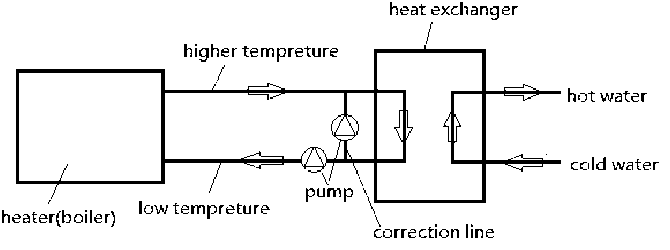
Figure 1. The experimental setup (a) Heat exchanger shell.
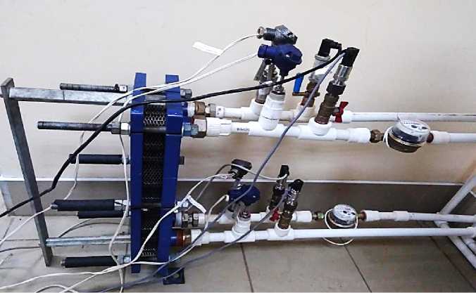
Figure 2. The experimental setup photo’s.
Description of measuring instruments
The matching device is multifunctional.
It is used to coordinate and enter into the PC the corresponding signals from the following sensors in the heat supply system:
–Pressure in the oil circuit to the mechanical flow switch.
–Pressure in the oil circuit after a mechanical flow breaker.
–Coolant flow rate in the oil circuit.
–Temperature in the supply line of the oil circuit.
–Temperature in the return pipe of the oil circuit.
–Temperature in the tank with fuel oil in the lower part.
–Temperature in the tank with fuel oil in the upper part.
The matching device is a combination of the following blocks:
–Power supplies for several output voltages.
–Four-channel information input device (NI 6009) from pressure transducers.

(a) Matching device
Figure 3. Measuring instruments.
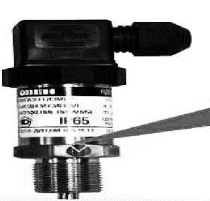
(b) Pressure transmitter PD100
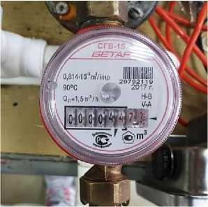
(c) Water meter “SGV-15D”BETAR
Analysis of test results
The purpose of this paragraph is the statistical processing of the results of a physical experiment and the correctness of recording experimental results.
A decrease in the error, and, consequently, an increase in the estimation accuracy, is always associated with an increase in the sample size. Therefore, already at the stage of organizing a sample observation, it is necessary to decide the question of what should be the size of the sample to ensure the required accuracy of the observation results.
It is necessary to carry out statistical processing of the source data: determine the absolute and relative measurement errors, discard the errors and correctly record the measurement result.
During the tests, the installation was previously filled with coolants. In stationary mode, after starting the pump to circulate the coolant, gradually increased the flow of cold water. Then the mixing ratio and temperature difference were calculated. The results of measurements of the installation in a stationary mode are shown in table 1.
k = (ti, -1 )/(t
- t c . w )
h. w mix mix where th ■ w - hot water temperature, °C; tmix — water temperature after mixing unit, °C; tc c. w_____
cold water temperature, °C.
Table 1.
THE RESULTS OF EXPERIMENTAL STUDIES
|
№ |
G cw . , m 3/ h |
G mix , m 3/ h |
G h . w , m 3/ h |
t cw , ° C |
t h . w ' ° C |
t mix ' ° C |
k |
|
1 |
0.045 |
1.440 |
1.395 |
12 |
78 |
74 |
0.065 |
|
2 |
0.077 |
1.333 |
1.257 |
14 |
80 |
74 |
0.100 |
|
3 |
0.115 |
1.161 |
1.047 |
12 |
81 |
72 |
0.150 |
|
4 |
0.205 |
1.125 |
0.920 |
14 |
78 |
61 |
0.362 |
|
5 |
0.232 |
1.059 |
0.827 |
10 |
78 |
56 |
0.478 |
|
6 |
0.364 |
1.000 |
0.636 |
10 |
78 |
54 |
0.545 |
|
7 |
0.375 |
0.973 |
0.598 |
10 |
78 |
50 |
0.700 |
|
8 |
0.377 |
0.947 |
0.570 |
10 |
78 |
50 |
0.700 |
|
9 |
0.391 |
0.923 |
0.532 |
10 |
78 |
48 |
0.789 |
|
10 |
0.421 |
0.878 |
0.457 |
10 |
78 |
47 |
0.838 |
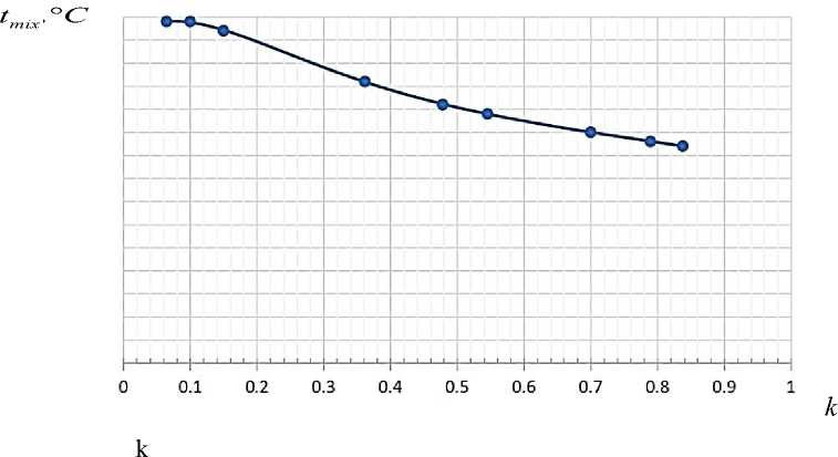
Figure 4 show the dependences of the change in the temperature of the mixture and the temperature difference of hot water and the temperature of the mixture, on the mixing ratio. The graph shows that in the stationary and pulsed modes with an increase in the mixing ratio, the temperature of the mixture decreases, and the temperature difference increases.
-
Figure 4. The temperature of the liquid after mixing.
Conclusion
The purpose of this test is to generate a pulsating flow through a pulsation generator to enhance heat transfer around the heat exchanger.
Assess the integrity of the task solution:
The structure of coil heat exchanger is designed. The development and testing of experimental samples of pulsed disk heat exchangers were carried out. The effect of pulsating frequency on heat transfer efficiency was obtained.
During the development of the experimental device, the heat transfer efficiency was improved, the time loss of industrial production equipment was reduced, and the time cost was reduced.
When the heat exchange efficiency of each frequency is considered in the experiment, it can be said that the heat exchange efficiency increases as the frequency increases. As the flow increases, so does the amount of heat exchange. The heat transfer rate can be increased by increasing the flow.
It can be inferred that within a certain frequency range, as the pulsation frequency increases, the heat transfer efficiency increases, and beyond this frequency, the heat transfer efficiency no longer increases or decreases. Therefore, it is necessary to find a suitable pulsation frequency according to the structure and characteristics of the heat exchange device, so as to achieve the effect of improving heat exchange efficiency, saving time and cost, and reducing energy consumption.
References Test of the layout of the correction circuit with a plate heat exchanger
- Arie M. A., Shooshtari A. H., Dessiatoun S. V., Al-Hajri E., Ohadi M. M. Numerical modeling and thermal optimization of a single-phase flow manifold-microchannel plate heat exchanger // International Journal of Heat and Mass Transfer. 2015. V.81. P. 478-489. DOI: 10.1016/j.ijheatmasstransfer.2014.10.022
- Kumar V., Tiwari A. K., Ghosh S. K. Application of nanofluids in plate heat exchanger: A review // Energy Conversion and Management. 2015. V. 105. P. 1017-1036. DOI: 10.1016/j.enconman.2015.08.053
- Sierra E., Acién F. G., Fernández J. M., García J. L., González C., Molina E. (2008). Characterization of a flat plate photobioreactor for the production of microalgae // Chemical Engineering Journal. V. 138. №1-3. P. 136-147. DOI: 10.1016/j.cej.2007.06.004
- Weft F. Study on heat transfer and scale removal of pulsating flow and wall vibration.
- Rao R. V., Patel V. Multi-objective optimization of heat exchangers using a modified teaching-learning-based optimization algorithm // Applied Mathematical Modelling. 2013. V. 37. №3. P. 1147-1162. DOI: 10.1016/j.apm.2012.03.043
- Duan Z. Indirect evaporative cooling: Past, present and future potentials // Renewable and Sustainable Energy Reviews. 2012.
- Durmuş A., Benli H., Kurtbaş I., & Gül, H. Investigation of heat transfer and pressure drop in plate heat exchangers having different surface profiles // International Journal of Heat and Mass Transfer. 2009. V. 52. №5-6. P. 1451-1457.
- DOI: 10.1016/j.ijheatmasstransfer.2008.07.052
- Kakaç S., Liu H. Heat exchangers: Selection, rating, and thermal design, second edition. CRC Press. 2002. P. 1-493.
- Al-Dawery S. K., Alrahawi A. M., Al-Zobai K. M. Dynamic modeling and control of plate heat exchanger // International Journal of Heat and Mass Transfer. 2012. V. 55. №23-24. P. 6873-6880.
- DOI: 10.1016/j.ijheatmasstransfer.2012.06.094
- Karellas S., Schuster A., Leontaritis A.-D. Influence of supercritical ORC parameters on plate heat exchanger design // Applied Thermal Engineering. 2012. V. 33-34. P. 70-76.
- DOI: 10.1016/j.applthermaleng.2011.09.013
- Ortega-Casanova J., Molina-Gonzalez F. Axisymmetric numerical investigation of the heat transfer enhancement from a heated plate to an impinging turbulent axial jet via small vortex generators // International Journal of Heat and Mass Transfer. 2017. V. 106. P. 183-194.
- DOI: 10.1016/j.ijheatmasstransfer.2016.10.064
- Staats W. L., Brisson J. G. Active heat transfer enhancement in air cooled heat sinks using integrated centrifugal fans // International Journal of Heat and Mass Transfer. 2015. V. 82. P. 189-205.
- DOI: 10.1016/j.ijheatmasstransfer.2014.10.075
- Yan K., Hong J., Zhang J., Mi W., Wu W. Thermal-deformation coupling in thermal network for transient analysis of spindle-bearing system // International Journal of Thermal Sciences. 2016. V. 104. P. 1-12.
- DOI: 10.1016/j.ijthermalsci.2015.12.007
- Mahmoudi Y., Karimi N. Numerical Investigation of Heat Transfer Enhancement in a Pipe Partially Filled with a Porous Material under Local Thermal Non-equilibrium Condition // International Journal of Heat and Mass Transfer. 2014. V. 68. P. 161-173.
- DOI: 10.1016/j.ijheatmasstransfer.2013.09.020
- Defraeye T., Blocken B., Carmeliet J. CFD Analysis of Convective Heat Transfer at the Surfaces of a Cube Immersed in a Turbulent Boundary Layer // International Journal of Heat and Mass Transfer. 2010. V. 53. №1-3. P. 297-308.
- DOI: 10.1016/j.ijheatmasstransfer.2009.09.029
- Chang S. W., Chiang K. F., Kao J. K. Heat Transfer in Rotating Spiral Channel with Two Opposite Planar Walls Roughened by Skew Ribs // International journal of thermal sciences. 2012. V. 56. P. 107-121.
- DOI: 10.1016/j.ijthermalsci.2012.01.018
- Guo C., Hu X., Cao W., Yu D., Tang D. Effect of Mechanical Vibration on Flow and Heat Transfer Characteristics in Rectangular Microgrooves // Applied thermal engineering. 2013. V. 52. №2. P. 385-393.
- DOI: 10.1016/j.applthermaleng.2012.12.010
