Testing of spacecraft orientation and stabilization systems using starry sky simulators

Author: Gorelko M.G., Murigin A.V.
Journal: Siberian Aerospace Journal @vestnik-sibsau-en
Section: Aviation and spacecraft engineering
Article in issue: 4 vol.23, 2022.
Free access
The paper investigates the need to create a method of simulating the starry sky for testing spacecraft and conducting tests of orientation and stabilization systems in laboratory conditions. Modern space exploration and, as a consequence, the complexity of technical requirements for flight support facilities are constantly increasing, respectively, the requirements for ensuring the accuracy of determining the position and orientation of the spacecraft are increasing. The history of the development of astroorientation devices and, in particular, stellar sensors is given. The modern stage of development of stellar sensors came with the advent of matrix radiation receivers: charged coupled device (CCD) and complementary metal-oxide semiconductor (CMOS) video matrices. Such stellar sensors are no longer tied to individual, predefined stars, but determine their orientation from images of groups of stars visible in the field of view of the device. Examples are given for their field of application, namely, determining the orientation of the sensor, pointing some device mounted on a spacecraft, and others. Modern requirements for astrogation are given. The basic principles of ground-based testing of the spacecraft orientation and stabilization system using starry sky simulators are considered. This is a stage of development and autonomous tests on a hardware and software stand of semi-natural modeling. To date, the ISS JSC enterprise has a complex modeling stand for conducting these types of spacecraft tests, using methods of both mathematical and semi-natural modeling, which includes various simulators of the starry sky. The development of these simulators has a long history, a comparative table of previously used simulators is given. The structures of both past and modern simulators of the starry sky are shown. The conclusions state the need to create a method that will simulate the rotation of the spacecraft at speeds up to 15–30 °/s. This method will allow testing the orientation and stabilization system of modern spacecraft.
Orientation and stabilization system, star sensor, starry sky simulator, dynamic tests, spacecraft
Short address: https://sciup.org/148329661
IDR: 148329661 | UDC: 629.78 | DOI: 10.31772/2712-8970-2022-23-4-688-695
Text of the scientific article Testing of spacecraft orientation and stabilization systems using starry sky simulators
Modern space exploration requires going beyond the limits of near-Earth orbits. As a result, the technical requirements for the means of ensuring the flight of a spacecraft (SC) are constantly increasing. In order to solve scientific problems, in particular, astrophysical ones, the requirements for ensuring the accuracy of determining the position and spacecraft orientation are constantly increasing[1; 2].
The developers of modern spacecraft are assigned with ensuring high accuracy of orientation and stabilization of the spacecraft in space. The success of the ongoing scientific experiments in space and the fulfillment of the target functions by the spacecraft depend on the solution of this problem.
Modern communication and navigation spacecraft are complex automated systems capable of solving a number of applied problems. There is a constant development of spacecraft in terms of their functional purposes, the complication of the applied and the introduction of new on-board systems, instruments and mechanisms.
A perfect example is the spacecraft orientation and stabilization system (SOS). SOS along with other methods for determining the spacecraft positioning, uses the method for determining the orientation relative to stars and planets, which is one of the main types of astroorientation [3].
There are several stages in the development of astroorientation. The first stage using visual orientation by the stars. It acquired special significance in the absence of clear landmarks on the ground such as among nomads and in navigation. Later there have appeared devices for more accurate measurements e.g. sextants, astrolabes, etc. Similar navigational skills and methods are still used today [4].
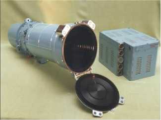
The second stage in the development of astroorientation started with the occurrance of aircraft (AC). Where after gyrocompasses became the main component of their orientation systems. These systems did not allow maintaining the orientation of the aircraft for a long time due to the so-called departure of gyroscopes - their precession under the influence of not fully taken into account external forces. Care control was carried out using star trackers (ST). The first generations of STs worked on several bright stars with known positions to solve problems of astroorientation. As a rule such STs had a system for pointing at a bright object and a system for keeping the direction to a captured object (fig. 1, а ). They appeared on board spacecraft and rockets and were used from the very beginning of space exploration. Already on the “Vostok” spacecraft they were used to align the spacecraft along the orbit. Information from the majority of devices of this generation was not processed on board the spacecraft, but was transmitted to the ground in the general telemetry stream. Orientation was calculated on the ground and then reported on board [5].
а
б в
г
Рис. 1. Приборы ориентации на звезды:
а – прибор ориентации на полярную звезду; б – БОКЗ-МФ; в – широкопольный звездный датчик 329К; г – звездный датчик SED-26; д – звездный датчик 348К (блок оптический)
д
Fig. 1. Star orientation devices:
a – polar star orientation device; b – BOKZ-MF; c – wide–field star sensor 329K; d – star sensor SED–26; e – star sensor 348K (optical unit)
The last stage in the development of the considered devices came with the advent of matrix radiation receivers: Charge Coupled Device(CCD) and Complementary metal-oxide semiconductor
(CMOS)video matrix. Such star sensors (SS) are not tied to individual, predetermined stars, but determine their orientation from the images of groups of stars visible in the field of view of the device (fig. 1, b–d ) [6].
Applications for star trackers
At the moment there are a number of tasks that can be solved with the help of a spacecraft attitude control system namely:
-
1) determination of the orientation of the three turning angles sensor relative to some coordinate system;
-
2) pointing some device installed on the spacecraft – an antenna, a solar battery, in a given direction.
This task is close to the previous one, but requires precise transfer of the orientation from the Star Sensor(SS) to the device;
-
3) drawing on some image, for example, the image of the Earth, a coordinate grid.
This is a typical task of Earth remote sensing. Additional but very important requirements for the listed tasks are the accuracy of determining the coordinates, the time for which these coordinates are determined, as well as operating dynamic range of determined angular velocities of the spacecraft [7; 8].
Modern requirements for astronavigation systems
As it was mentioned before the development of spacecrafts continues constantly, they are faced with more and more complex tasks and their functionality is increasing e.g :
-
– the need to use lasers as information transmitters both from orbit to earth and between spacecrafts. The use of low-power lasers with small divergence angles requires the transmitter to be pointed at the receiver and held with an accuracy better than 0,05 ";
-
– modern meteorology requires obtaining maps of the Earth's cloud cover with a resolution of 10 m. For geostationary weather satellites, this corresponds to a resolution and orientation accuracy of at least 0,05 ";
-
– attitude control systems on fast maneuvering spacecrafts should determine their orientation at least 10 times per second with an accuracy of no worse than 0,1–1 " [8].
To fulfill the tasks set the developers of new spacecrafts are subject to higher requirements for new star sensors.
New generation sensors should provide:
-
1) accuracy of determining the orientation of the spacecraft 0,1–0,01";
-
2) navigation information update time 10–100 ms ;
-
3) determination of coordinates and angular velocities at spacecraft rotation speeds up to 15–30 °/s .
-
4) The star sensor must operate in a wide range of angular velocities of rotation of the spacecraft, from 0 to one rotation per few seconds, and at the same time provide high orientation accuracy at low rotation speeds and moderate accuracy at high rotation velocities. [8].
Development of star trackers in laboratory conditions
One of the main stages in the design and development of SOS spacecraft is the stage of developmental and autonomous tests on a hardware-software stand for half-life simulation. The purpose of this stage is experimental confirmation of the operation of the SOS onboard equipment under conditions close to operational ones. [9–11].
At the moment JSC “Academician M. F. Reshetnev “Information Satellite Systems” has a complex modeling stand (CMS) that uses methods of both mathematical and semi-natural modeling to carry out these types of spacecraft tests. [12–14]. The structure and principle of building a complex simulation stand provide opportunities for system checks that cannot be achieved by other means [15].
Since modern star sensors are faced with a wide range of tasks such as increasing the accuracy of determining coordinates at a high polling rate and successfully determining coordinates at high speeds of rotation of the spacecraft, this leads to the need to modernize the means of simulating the starry sky which are necessary for testing the performance of the SOS spacecraft.
At the very beginning starry sky simulators (SSS) creating the static light of a single star were developed. They imitated some kind of reference point on the celestial vault. Further sky simulators imitating light of a group of stars were developed. Both those and other sky simulators work by using a screen with holes and a long throw projection lens.
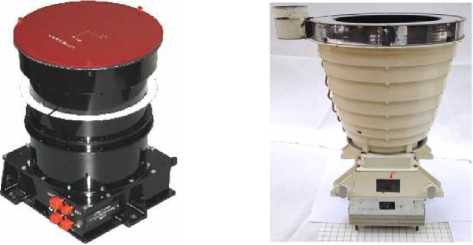
Then sky simulators of the previous generation were replaced by ones that dynamically simulate stars using monochrome displays with a wide dynamic range of luminosity, mainly manufactured for medical equipment. They made it possible to simulate the position and angular velocity of stars. (fig. 2) [16].
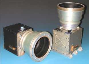
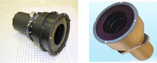
And as the final stage, there was the creation and development of starry sky simulators based on microdisplays (Fig. 3). The table shows the main characteristics of the starry sky simulators existing as part of a complex modeling stand (CMS) [17; 18].
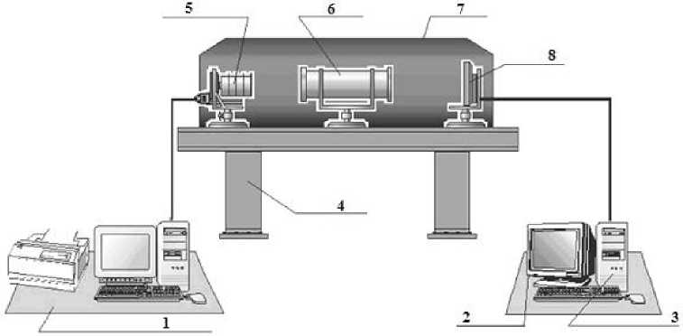
Рис. 2. Динамический стенд имитации группы звезд (ДСИГЗ):
1 – к онтрольно-испытательная аппаратура (КИА); 2 – монитор оператора; 3 – персональный компьютер со звездными каталогами; 4 – станина; 5 – испытываемый прибор (329К);
6 – коллиматорный объектив; 7 – светозащита; 8 – цифровой монитор высокой четкости
Fig. 2. Dynamic simulation stand of a group of stars (DSSGS):
1 – control and testing equipment (CTE); 2 – operator monitor; 3 –personal computer with star catalogs;
4 – bed; 5 – test device (329K); 6 – collimator lens; 7 – light protection; 8 – high definition digital monitor
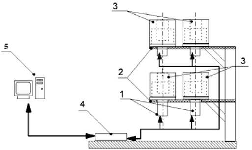
Рис. 3. Структура имитатора звездного неба на основе проекционных систем (ИЗН ПС):
1 – блок оптический звездного датчика 348К; 2 – плита установочная;
3 – оптический модуль ИЗН ПС; 4 – блок электроники звездного датчика 348К;
5 – к онтрольно-испытательная аппаратура
Fig. 3. The structure of the starrysky simulators based on projection systems (SSS PS):
1 – the optical unit of the star sensor 348K; 2 – the installation plate; 3 – optical module SSS PS;
4 – electronics unit of the star sensor 348K; 5 – control and testing equipment
The observed rapid development of technical means of virtual and augmented reality has led to the continuous improvement of technologies for creating microdisplays with a diagonal size of up to one inch, which made it possible to use them in the construction of means for optically simulating the starry sky of small sizes sufficient to be able to fix them on star sensor hoods. At present there is a transition to new types of starry sky simulators built on the basis of microdisplays. This leads to the need of modernization the existing methods for testing SOS AC including star sensors. In addition, the constant increase in the operating range of the measured angular velocities of rotation of the celestial vault by star sensors leads to the fact that microdisplays with an ever higher image refresh rate are required. This is because the screen refresh rate increases, the period decreases and therefore the maximum simulated angular velocity also increases, since it is equal to the ratio of the average angular size of the stars to this period value. At present, the limiting refresh rate of the microdisplay image can reach up to 90 Hz, which allows solving most tasks for working out the SOS of a spacecraft. .
Since star sensors are gradually being introduced to obtain position data at higher rotational speeds relative to the until recently considered normal values of angular velocities, there is a need to develop a method for dynamic imaging of the starry sky which would allow the star sensor to "see" the rotating celestial vault at these angular speeds.
Specifications of starry sky simulators
|
DSSGS for SS 329К |
CTE for SS SED 26 |
CTE for SS 348К |
CTE for SS 348К |
SSS PS |
|
|
Working with SS optical blocks at the same time |
1 |
– |
– |
2 |
4 |
|
Field of regard |
22 ° x18 ° |
– |
– |
23 ° x23 ° |
19 ° x19 ° |
|
Range of simulated angular velocities of the spacecraft |
No more than 1.6 deg./s |
В рамках работы прибора |
During the operation of the device |
±1 deg./s |
3 deg./s |
|
Imitation of the starry sky sections |
О |
E |
E |
О |
О |
|
Ability to work with other SS |
– |
– |
– |
+ with revision |
+ with revision |
Примечание. O – оптическая имитация, Э – электронная имитация, ОБ – оптический блок. Note. O- optical simulation, E-electronic imitation, OB-optical block Conclusion
Modern tasks of space navigation require the creation of a new generation of stellar orientation and this in turn leads to the development of a methodology for testing spacecraft orientation and stabilization systems using starry sky simulators built on the basis of various types of microdisplays which will use the method of dynamic formation of an image of a star of the sky taking into account the peculiarities of the operation of matrix photodetectors used in SOS spacecraft star sensors.
This method will allow simulating the rotation of the spacecraft at speeds up to 15–30°/s which will lead to the possibility of testing the SOS of modern spacecrafts.
References Testing of spacecraft orientation and stabilization systems using starry sky simulators
- Gladyrevskiy A. G., Gubarenko S. I. [Methods and algorithms of spacecraft orientation using an astrosystem]. Exponenta Pro. Matematika v prilozheniyakh. 2003. No. 1. P. 60–65 (In Russ.).
- Popov V. I. Sistemy orientatsii i stabilizatsii kosmicheskikh apparatov [Systems of orientation and stabilization of spacecraft]. Moscow, 1986,184 p.
- Kovalev E. A., Dernov S. A. [Technology for testing spacecraft orientation and stabilization systems]. SAKS 2004, Tez. Dokl. III Mezhdunarod. Nauchno-prakt. Konf. SybGAU. Krasnoyarsk, 2004. P. 97–99 (In Russ.).
- Kononovich E. V., Moroz V. I. Obshchiy kurs astronomii [General course of astronomy]. Moscow, Unitorial URSS, 2004, 544 p.
- Osipik V. A., Fedoseev V. I. [Algorithms for automatic recognition of groups of stars on board the spacecraft]. Opticheskiy zhurnal. 1998, No. 8, P. 32–40.
- Mironov A. V. Osnovy astrofotometrii. Prakticheskie osnovy fotometrii i astrofotometrii zvezd [Fundamentals of astrophotometry. Practical fundamentals of photometry and astrophotometry of stars]. Moscow, Fizmatlit Publ., 2008, 258 p.
- Fedoseev V. I., Kolosov M. P. Optiko-elektronnye pribory orientatsii i navigatsii kosmicheskikh aparatov: ucheb. posobie [Optical-electronic devices for orientation and navigation of space apparatuses: textbook. manual]. Moscow, Logos Publ., 2007, 248 p.
- Prokhorov M. E., Zakharov A. I., Mironov A. V., Nikolaev F. N., Tuchin M. S. [Modern sensors of stellar orientation]. Fizika Kosmosa. Trudy 38 mezhdunarodnoy studencheskoy nauchnoy konferentsii. Yekaterinburg, 2009, P. 170–186.
- Strogalev V. P., Tolkacheva I. O. Imitatsionnoe modelirovanie [Simulation modeling: textbook]. Moscow, Bauman Moscow State Technical University Publ., 2008, 280 p.
- Sinitsky D. E., Dernov S. A. [Development of the basic principles of using semi-natural modeling methods for testing modern spacecraft orientation and stabilization systems]. Vestnik SibGAU. 2013, No. 4, P. 119–129.
- Sinitskiy D. E., Fedchenko D. A., [Problem Solving ground experimental development oriwntation and stabilization system of spacecraft using simulators inverted type]. Aktual’nyye problemyy avyacyy I kosmonavtyky: materyalyy VIII Vseros. Nauch.- prakt. Konf. SybGAU. – Krasnojarsk, 2012, No. 8, P. 44–45 (In Russ.).
- Baryshnikov N. V. [Bauman Moscow State Technical University, The use of semi-natural modeling methods in the design of complex laser optoelectronic systems]. Nauka i obrazovanie. 2011, No. 2, P. 70 (In Russ.).
- James J., Howell W. E. Simulator study of a satellite attitude control system using inertia wheels and a magnet / Langley Research Center. Langley Station, Humpton: Va. NASA technical note 63-21893, Oct. 1963. Available at: http://ntrs.nasa.gov.
- Schwartz J. L., Hall C. D. The Distributed Spacecraft Attitude Control System Simulator: Development, Progress, Plans, 2003. Flight Mechanics Symposium. Goddard Space Flight Center. Greenbelt, Maryland, October 28–30. 2003.
- Hoop H. Facilities for simulating attitude motion of a spacecraft / Research Branch Redstone Scientific Information Center Research and Development Directorate U. S. Army Missile Command Redstone Arsenal. NASA Technical report 35809-30. Alabama, 1967. Available at: http://ntrs.nasa.gov.
- NRDC.203116.003 RE Dinamicheskiy stend imitatsii gruppy zvezd dlya pribora zvezdnogo viziruyushchego (PZV) [Dynamic simulation stand of a group of stars for a star sighting device (SRV)] Operating Manual.
- OSI (Optical Sky Stimulator) Jena Oprtronik. Available at: http://www.jena-optronik.de.
- Catalogues of the starry sky. Available at: http://www.astromyth.ru/Astronomy/Catalogs.html.
