Testing of the model of the heat exchanger supercharger with a flat active part

Author: Zhang Qianwen, Liu Chunyan, Peng Yan, Levtsev Aleksei
Journal: Бюллетень науки и практики @bulletennauki
Section: Технические науки
Article in issue: 1 т.7, 2021.
Free access
This paper designs a pulsation-generating structure to provide pulsating flow for experiments. The relationship between frequency, flow and pulsating flow enhancement heat transfer is discussed separately. The characteristics of pulsating flow enhanced heat transfer are analyzed, and the theoretical research and engineering application of pulsating heat transfer are proposed. The scheme of the laboratory installation is developed, which is an independent circuit from the heat source with a pulse circulation of the coolant. The unit allows testing the heat exchanger-supercharger at different performance at the frequency of fluctuations of the coolant from 0.5 to 2 Hz. As a result of thermal tests, graphs of temperature changes over time in the heated and closed circuit at flow interruption frequencies from 0.5 to 1 Hz are obtained. It is found that with increasing frequency of flow fluctuations, the heating time of the coolant in a closed loop decreases by almost 1.85 times.
Pulsating generator, pulsating flow, frequency, heat transfer
Short address: https://sciup.org/14117929
IDR: 14117929 | UDC: 621.565.95 | DOI: 10.33619/2414-2948/62/23
Text of the scientific article Testing of the model of the heat exchanger supercharger with a flat active part
Бюллетень науки и практики / Bulletin of Science and Practice
UDC 621.565.95
Research Background and Theoretical Research
In the development and utilization of energy, problems related to heat transfer are quite common. Heat transfer enhancement plays an important and even key role in energy development, utilization and conservation. The rapid development of applied science and technology and the serious shortage of energy put forward new requirements for strengthening heat exchange. Therefore, the depth and breadth of heat transfer enhancement research is expanding and penetrating into new fields and has become a very attractive research field in modern science.
In practical industrial production, heat exchanger is the most common application of heat transfer enhancement technology. Heat exchanger is an indispensable component to ensure the normal operation of engineering equipment in various industrial production processes and occupies an important share in the metal consumption, power consumption and investment of the whole project. The research on heat transfer enhancement of heat exchanger is mainly concentrated in two aspects. The first is to develop new types of heat exchangers, such as plate-fin type, parallel flow type, vibrating coil type, micro-channel type and other compact heat exchangers. The second is to strengthen the traditional shell and tube heat exchanger.
According to the motion state of fluid, flow can be divided into steady flow and unsteady flow. In recent years, unsteady flow has attracted the attention of many scholars for its unique physical characteristics and research value, while pulsating flow is the basic research of unsteady flow. Pulsating heat transfer is a typical application of unsteady flow and heat transfer technology. The heat transfer of turbulent pulsation is an important component. Pulsating flow heat transfer is a mechanical method in active heat transfer technology, which makes use of external conditions to make the flow change circularly.
Nishimura et al. studied and analyzed the fluid flow field change and pressure drop in a twodimensional wave-walled tube [1–2]. The results show that the motion state of the fluid changes with the change of the Reynolds number, for example, the vortex phenomenon will appear in the flow in the laminar flow state, and the vortex size will increase with the increase of the Reynolds number. Later, Nishimura [3–5] used visualization experiments to study the pulsating flow in the corrugated channel and found that the size of the vortex generated in the groove of the corrugated channel was closely related to the flow velocity of the fluid, and the vortex could accelerate the mixing of the fluid. Attya and Habib [6] studied the correlation between the pulsating frequency of medium flow with air as the medium and Reynolds number and Nusselt number in laminar flow state. The results show that when the medium is at constant heat flux density, the Nusselt number changes obviously with the change of pulsation frequency. It is found that the pulsating flow of the fluid has a significant effect on enhancing heat transfer.
Zhong Yingjie's [7–8] research group of Zhejiang University of technology has systematically studied the pulsating flow heat transfer. The metering pump was used as the pulsation source in the experiment, and laminar flow was taken as the main research condition. The study found that: for the periodic groove heat transfer surface, the pulsation flow could improve the heat transfer performance by about 80% compared with the steady-state flow. On this basis, they used visualization experiments to further study the mechanism of heat transfer enhancement by pulsating flow. It is found that the variation rules of vortex in the flow field are different at different pulsating frequencies, and there is a pulsating frequency that can optimize the heat transfer effect. Under the optimal pulsating frequency, the vortex has enough time to develop and fully expand in the groove, and finally falls off into the mainstream in time. When the frequency is too high, the vortexes in the channel will fall off quickly without sufficient development and expansion, resulting in insufficient mixing of the fluids in the channel and the mainstream fluid, so the heat transfer effect is not good. Yang Bingchang [9] et al. from Dalian University of technology also carried out an experimental study on the periodic groove structure with different structural parameters and analyzed in detail the specific influence of different Reynolds number Re, Strouhal number St and pulsating amplitude A on the heat transfer effect. It is found that the heat transfer enhancement factor of pulsating flow first increases and then decreases with the increase of St number of Strouhal number, so there is an optimal St number of Strouhal number to maximize the heat transfer enhancement factor.
Zeng Danling’s [10] research group of Chongqing University also carried out simulation and experimental research on the heat transfer problem of pulsating flow enhancement, which adopted Helmholtz self-excited oscillation cavity as the pulsating source. The pulse jet generated by the Helmholtz resonant cavity is introduced into the heat exchanger to generate pulsating flow at the inlet of the heat exchanger. When the self-excited oscillation reaches a certain intensity, the performance of the heat exchanger can be enhanced. The pulsation of the fluid creates a large number of vortices on the wall, which increases the mixing of the fluid. Different oscillation intensities correspond to different intensification heat transfer effects. There is an optimal intensity with the best intensification heat transfer effect, and the surface heat transfer coefficient will be increased by about 30%.
Muller studied pulsating flow heat transfer and steady-state heat transfer under specific conditions through experiments. The pulsating frequency of the pulsating flow involved in the experiment increased from 0.038Hz to 0.248Hz, and the Reynolds number increased from 53000 to 76000.The experimental results show that Nu under pulsating conditions is smaller than Nu under corresponding steady-state conditions. Ishino [11] studied the influence of pulsating flow on the heat transfer performance of the fluid in the tube under the condition of constant wall temperature through experiments. The pulsation frequency was controlled from 17.7hz to 35.5h, and the Reynolds number was changed from 8000 to 12800. The experimental results show that when pulsating flow is added to the turbulent area, the heat transfer performance decreases with the increase of pulsating amplitude and pulsating frequency, up to 50%.
Experimental Research
In the course of the study, all the work of the flow energy Converter was divided into 3 stages in order to more accurately understand the nature of the forces arising and more accurately determine the desired parameters on the obtained model.
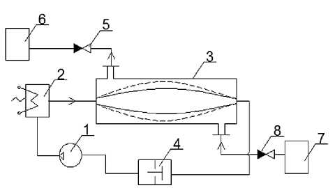
Figure 1. Work concept heat exchanger–supercharger.
-
1 - pump
-
2 - boiler
-
3 - beat exchanger-supercharger
-
4 - shock valve
-
5 - check valve
-
6 - hot water tank
-
7 - cold water tank
-
8 - check valve
Both circuits are filled with water before starting operation. Then turn the pump 1 and the boiler 2. The pump 1 circulates in the heating circuit and the heat from the boiler 2 is transferred to the heat exchanger-supercharger 3. Next, include the drive of the shock valve 4 and it is periodically closed and opened. At the moment of closing the shock valve 4, a reverse wave of increased pressure occurs, which expands the inner surface and displaces the inner volume from the heat exchanger of the supercharger 3 through the check valve 5 to the hot water tank 6. Further, when the shock valve 4 is opened, the inner surface is compressed by the action of elastic forces and the inner cavity of the heat exchanger-supercharger is filled with cold water from the cold water tank 7 through the check valve 8.
Analysis of test results
Shows the results of 6 experiments from the LGraph program.
For figure 2 graph of temperature changes over time in the heating and closed loop at the frequency of interruption of the flow of 0.5 Hz (this corresponds to the frequency of the supply voltage of 10 Hz).
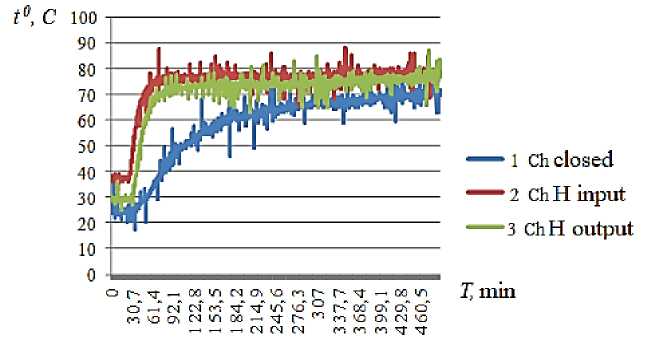
Figure 2. Graph of temperature changes over time in the heating unit and a closed loop at a flow interruption frequency of 0.5 Hz.
As can be seen from this graph, the temperature of the coolant in the heated (closed) circuit increases exponentially and reaches the set value in 460 seconds.
For figure 3 according to the results of the second experiment, a graph of temperature changes over time in the heating and closed loop at the frequency of interruption of the flow of 0.6 Hz (this corresponds to the frequency of the supply voltage of 12 Hz) is shown.
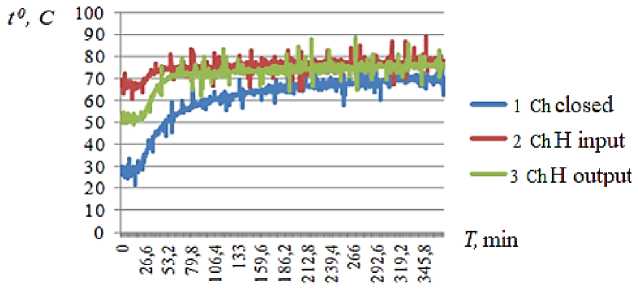
Figure 3. Graph of temperature changes over time in the heating unit and closed loop at a flow interruption frequency of 0.6 Hz.
As can be seen from this graph, the temperature of the coolant in the heated (closed) circuit increases exponentially and reaches the set value in 345 seconds.
In the results of the third experiment from the L Graph program.
Figure 4 shows a graph of temperature changes over time in the heating and closed loop at the frequency of flow interruption of 0.7 Hz (this corresponds to the frequency of the supply voltage of 14 Hz).
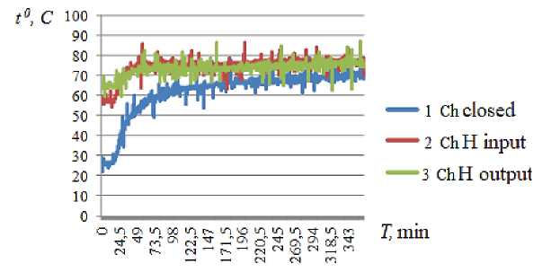
Figure 4. Graph of temperature changes over time in the heating unit and closed loop at a flow interruption frequency of 0.7 Hz.
As can be seen from this graph, the temperature of the coolant in the heated (closed) circuit increases exponentially and reaches the set value in 343 seconds.
In the results of the fourth experiment from the L Graph program. For Figure. 5 graph of temperature changes over time in the heating and closed loop at the frequency of interruption of the flow of 0.8 Hz (this corresponds to the frequency of the supply voltage of 16 Hz).
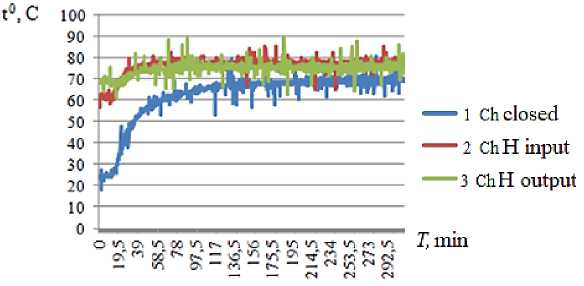
Figure 5. Graph of temperature changes over time in the heating unit and closed loop at a flow interruption frequency of 0.8 Hz
As can be seen from this graph, the temperature of the coolant in the heated (closed) circuit increases exponentially and reaches the set value in 292 seconds.
Figure 6 shows a graph of temperature changes over time in the heating and closed loop at the frequency of interruption of the flow of 0.9 Hz (this corresponds to the frequency of the supply voltage of 18 Hz) about exponential dependence and reaches the set value in 292 seconds.
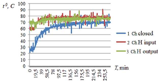
Figure 6. Graph of temperature changes over time in the heating unit and closed loop at a flow interruption frequency of 0.9 Hz.
As can be seen from this graph, the temperature of the coolant in the heated (closed) circuit increases exponentially and reaches the set value in 253 seconds.
Figure 7 shows a graph of temperature changes over time in the heating (closed) circuit at a frequency of interruption of the flow of 1 Hz (this corresponds to the frequency of the supply voltage of 20 Hz).
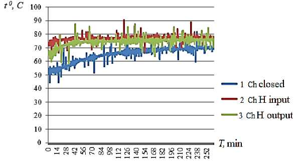
Figure 7. Graph of temperature changes over time in the heating unit and closed loop at a flow interruption frequency of 1 Hz.
As can be seen from this graph, the temperature of the coolant in the heated (closed) circuit increases exponentially and reaches the set value in 249 seconds.
Figure 8 shows a graph of changes in the flow rate of the coolant from the frequency of the supply voltage in a closed loop.
As can be seen from this graph, the flow rate of the coolant in the heated (closed) circuit increases to the maximum value at a frequency of about 16 Hz.
Based on the results of the calculation, the graphs of the amplitude frequency response and phase-frequency response and frequency response of the circuit are constructed at 3 mass values: 2.7;5.4; 8.1 kg.
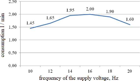
Figure 8. Graph of the dependence of the coolant flow rate on the frequency of the supply voltage in the heated (closed) circuit.
The frequency response graph shows that with an increase in mass by 2 times in relation to the base value (m=2.7 kg), the amplitude of the pressure increment at a frequency of 5 Hz increases by 3 times, and with an increase in mass by 3 times increases by 7 times. As for the frequency response, at a frequency of 5 Hz, the pressure lags behind the phase flow rate (-1.6 rad.) for all mass values.
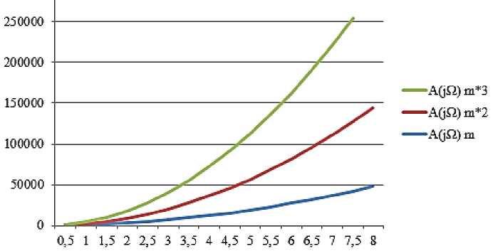
Figure 9. Amplitude frequency response energy circuit.

Figure 10. Phase frequency response energy circuit.
Conclusion
A review of the most well-known non-volatile hot water heating systems for industrial and household needs has shown that the efficiency of such systems no longer meets the requirements of today in terms of their energy efficiency. The greatest demand is for non-volatile systems with non-traditional and renewable energy sources. However, the effectiveness of the latter is still low. Using the potential of pulse systems, as well as combining the functions of heat transfer and supercharger will make such systems more attractive.
A model sample of a heat exchanger-supercharger with a capacity of 200 l/h with a soldered active part made of copper sheets, which have a large number of loading cycles, has been developed.
The scheme of the laboratory installation is developed, which is an independent circuit from the heat source with a pulse circulation of the coolant. The unit allows testing the heat exchangersupercharger at different performance at the frequency of fluctuations of the coolant from 0.5 to 2 Hz.
A mathematical model of a laboratory installation with a supercharger heat exchanger in the form of an energy chain has been developed, which allows predicting the available head (pressure) at the supercharger outlet for different water masses in the circuit. It is found that with increasing water mass in the circuit, the pressure increment to the flow rate increases at the same frequency. The increment of pressure to flow (hydraulic resistance) the greater it is the higher the heat transfer according to the Reynolds hypothesis.
As a result of thermal tests, graphs of temperature changes over time in the heated and closed circuit at flow interruption frequencies from 0.5 to 1 Hz are obtained. It is found that with increasing frequency of flow fluctuations, the heating time of the coolant in a closed loop decreases by almost 1.85 times.
References Testing of the model of the heat exchanger supercharger with a flat active part
- Nishimura T., Ohori Y., Kawamura Y. Flow characteristics in a channel with symmetric wavy wall for steady flow // Journal of chemical engineering of Japan. 1984. V. 17. №5. P. 466-471. DOI: 10.1252/jcej.17.466
- Nishimura T., Kojima N. Mass transfer enhancement in a symmetric sinusoidal wavy-walled channel for pulsatile flow // International Journal of Heat and Mass Transfer. 1995. V. 38. №9. P. 1719-1731. DOI: 10.1016/0017-9310(94)00275-Z
- Nishimura T., Oka N., Yoshinaka Y., Kunitsugu K. Influence of imposed oscillatory frequency on mass transfer enhancement of grooved channels for pulsatile flow // International journal of heat and mass transfer. 2000. V. 43. №13. P. 2365-2374. DOI: 10.1016/S0017-9310(99)00311-7
- Nishimura T., Matsune S. Vortices and wall shear stresses in asymmetric and symmetric channels with sinusoidal wavy walls for pulsatile flow at low Reynolds numbers // International Journal of Heat and Fluid Flow. 1998. V. 19. №6. P. 583-593. DOI: 10.1016/S0142-727X(98)10005-X
- Nishimura T., Bian Y. N., Kunitsugu K. Mass-transfer enhancement in a wavy-walled tube by imposed fluid oscillation // AIChE journal. 2004. V. 50. №4. P. 762-770. DOI: 10.1002/aic.10070
- Habib M. A., Attya A. M., Eid A. I., Aly A. Z. Convective heat transfer characteristics of laminar pulsating pipe air flow // Heat and mass transfer. 2002. V. 38. №3. P. 221-232.
- DOI: 10.1007/s002310100206
- Li H., Zhong Y., Zhang X., Deng K., Lin H., Cai, L. Experimental Study of Convective Heat Transfer in Pulsating Air Flow inside Circular Pipe // Challenges of Power Engineering and Environment. 2007. P. 880-885.
- DOI: 10.1007/978-3-540-76694-0_164
- Zhong Y., Deng K., Zhao S., Hu J., Zhong Y., Li Q., … Wen Q. Experimental and Numerical Study on Hydraulic Performance of Chevron Brazed Plate Heat Exchanger at Low Reynolds Number // Processes. 2020. V. 8. №9. P. 1076.
- DOI: 10.3390/pr8091076
- Yang B. C., Jin D. X. An Experimental Investigation of Heat Transfer Enhancement by Pulsating Laminar Flow in a Triangular Grooved Channel // Advanced Materials Research. 2012. V. 516-517. P. 249-252.
- DOI: 10.4028/www.scientific.net/amr.516-517.249
- Wu S., Zeng D. Analysis of Effect of Fouling on Thermodynamic Performance of Convective Heat Transfer Process Through a Duct // Advanced Energy Systems. 2002.
- DOI: 10.1115/imece2002-33146
- Ishino Yo., Suzuki M., Abe T., Ohiwa N., Yamaguchi Sh. Flow and Heat Transfer characteristics in pulsating pipe flows (effects of pulsation on internal Heat Transfer in a circular pipe flow) // Heat Transfer. 1996. V. 25. №5. 323-341.
