The analytical solution and the dynamic characteristics of the system model velocity control vibrating roller

Author: Prokopiev Andrey P., Ivanchura Vladimir I., Emelianov Ruric Т.
Journal: Журнал Сибирского федерального университета. Серия: Техника и технологии @technologies-sfu
Article in issue: 4 т.7, 2014.
Free access
Operation is devoted a problem of identification of dynamic system of the volume hydraulic actuator of the running gear of a vibrating roller. The mathematical model of control process by speed of driving of a vibrating roller taking into account dynamics of hydrostatic transmission and a moment of resistance to roller driving is observed. Assay values of dynamic responses, a frequency analysis of a model of a guidance system are resulted by speed of driving of a vibrating roller.
Vibrating roller, hydrostatic transmission, mathematical model, state space, dynamic responses, frequency analysis
Short address: https://sciup.org/146114866
IDR: 146114866 | UDC: 625.084/085:625.855.3
Аналитическое решение и динамические характеристики модели системы управления скоростью движения вибрационного катка
Работа посвящена задаче идентификации динамической системы объёмного гидравлического привода ходовой части вибрационного катка. Рассмотрена математическая модель процесса управления скоростью движения вибрационного катка с учетом динамики гидрообъёмной трансмиссии и момента сопротивления движению катка. Приведены результаты анализа динамических характеристик, частотный анализ модели системы управления скоростью движения вибрационного катка.
Text of the scientific article The analytical solution and the dynamic characteristics of the system model velocity control vibrating roller
Most common in modern technologies of road construction in the final compaction of Hot Mix Asphalt (HMA) were vibrating road rollers. The need to improve the compaction asphalt concrete pavement process is the development of automated control vibrating roller on the basis of modern science and technology [1].
The purpose of research is to develop a model of the process speed control vibrating roller and analysis of the dynamic responses in preparation for the task of system synthesis control modes of compaction.
The original mathematical description of the system and the formulation of the problem
Roller is a machine, which consists of: engine, the front and back frames, the cabin, the mechanism of asphalt concrete edging. The working body of the roller is smooth metal drum with vibrations [2].
The hydraulic actuator of a driving of the vibration road roller with two power-driven rollers, Fig. 1, includes the variable capacity pump of the course drive and in parallel joint two hydromotors. The hydraulic actuator of the roller as control system, it is possible to present in the form of two
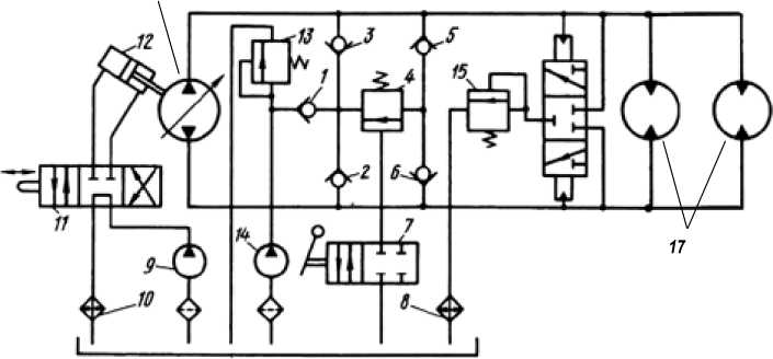
Fig. 1. Hydraulic circuit design VHT of the drive of the mechanism of movement [2]: 1, 2, 3, 5, 6 – back-pressure valves; 4, 13 – relief valves; 7, 11 – the spool-type allocator; 8, 10 – a cooler; 9 – the pump; 12 – an actuator; 14 – the feed pump; 15 – a release valve; 16 – the variable capacity pump; 17 – noncontrollable hydromotors
subsystems: the hydraulic and the hydromechanical. The state variable characterising a hydraulic subsystem, magnitude of hydraulic pressure P ( t ) of a stream of the operating fluid, created by the pump concerning pressure in a drain forecastle is. The state variable characterising a hydromechanical subsystem, magnitude ω m ( t ) of speed of twirl of the hydromotor, under the pressure influence of a fluid stream is.
The volume hydrostatic transmission (VHT) the drive of a driving of a running roller (Fig. 1) switches on the variable capacity pump 16 and two noncontrollable hydromotors 17 connected in parallel to a hydraulic line.
As a result of transformations the mathematical model in terms of state-space presenting working process of system of automatic control by speed of driving of a vibrational running roller [3] is gained.
Analytical transformation of transfer functions
For the purpose of reduction of gained models transfer functions [3] to the shape of the most matching to conditions of computer (imitative) simulation of processes in the volume hydraulic actuator of the road roller following analytical transformations are executed.
Transfer functions [3] be presented two types of transfer functions W 1 ( s ) or W 2 ( s ):
W 1 ( s ) =
K 1
s 2 + 2 • a • s + a 2 + в 2
W 2 ( s ) =
K 2 ■ ( s + Y)
.
s + 2 ■ a ■ s + a + в
Here K 1 , K 2 – factors; α, β, γ – the real positive numbers. Numbers α and β define the real and imaginary parts of poles, and γ – value of null of a matching transfer function.
Impulse response k 1 ( t ) and step response h 1 (1 ) performances for W 1 (5 ) are defined by an inverse transformation method of Laplace (transition from images to originals):
* 1 ( t ) = ^. e - a' t . sin(e • t );
h i ( t ) =
K 1
*
в - ( в2 + a2 )
e - a * t
в - 1 + arctg l в
— в
Impulse response k 2( t ) and step response h 2( t ) performances for W 2( 5 ) are defined by an inverse transformation method of Laplace:
K 2 . - a - t в
( (y - a) - sin (в - t ) + в - cos (в - 1 ) )
K 2
в-(e2 + a2)
•^ Y ’ в + e a' t ^ ( a 2 +в 2 )
• sin (в • t ) - y • (a • sin (в • t )+в • cos (в • t ))
From expressions for time responses follows, that value α defines fading, and value β – an angular frequency of dynamic processes.
Through factors of the state- space equation [3] express as follows:
- ( a ll + a 22 ) .
2 \ I a + ai2 • a21 - an • a22 II ;
Y pu = a2 22 ; Y m = "a 11;
K pu = b 11 ; K pm = a12 • b 22 ;
K и u = a 21 • b lb K и m = b 2 2 .
Definition of transfer functions of installation of control on the basis of transfer functions W i ( 5 ) or W 2 ( 5 ) gained by an analytical method:
|
W pu ( s ) = 2 s + Y pu ) 2 ; s + 2 • a • s + a + в |
(3) |
|
K pm Wpm ( s ) -2. 2 2 ; s + 2 • a • s + a + в |
(4) |
|
^ o u ( s ) = - 2 ^ “ u 2 2 ; s + 2 ' a ' s + a + в |
(5) |
|
У/ \ Wto m ( s ) =- 2ю m4 s + Y2m m ) 2 . s + 2 ' a • s + a + e |
(6) |
Here Wpu (5) - a transfer function defining change of pressure concerning change of control action; Wpm(5) - a transfer function defining change of pressure concerning change of dithering impact; Wmu(5) - a transfer function defining change of an angular velocity of twirl of rollers concerning – 482 – change of control action; Wωm(s) – a transfer function defining change of an angular velocity of twirl of rollers concerning change of dithering impact; Kpu, Kpm, Kωu, Kωm – factors; α, β, γpu, γωm – the real positive numbers. Numbers α and β define the real and imaginary parts of poles, and γpu, γωm – value of null of a matching transfer function.
Impulse response kpu ( t ) and step response hpu ( t ) performances for Wpu ( s ):
K kpu (t) --J- • e -((Y pu- a) •sin(e • t)+e •cos(e • t));
h pu ( t ) - / 2 pu 2\ •[ y pu 'e + e a ' t {( a 2 + e 2 ) • sin(e • t ) - Y pu •(a • sin (P • t ) + e • cos (P • t »]] .
Impulse response k pm ( t ) and step response h pm ( t ) performances for W pm ( s ):
k pm ( t ) - K-^ );
K Г hpm (t) = TlpmTi' e"“'t ' J(в2 + “ ) ' sin I в ' t + arctg I “II" в в .|p2 + a2) L I V a))
Impulse response k ω u ( t ) and step response h ω u ( t ) performances for W ω u ( s ):
K
"a' t • sin(e • t );
7_ Z,\ ® u —K kЮ U (t ) = в e
в ^( в 2 + a 2 ) L ^ ' I Ia»
Impulse response k ω m ( t ) and step response h ω m ( t ) performances for W ω m ( s ):
k ® m ( t ) = -7 m • e "at • ((Y ® m - a) • sin(e • t ) + в • cos(e • t ));
β
h ® m ( t ) =
K ω m в - ( ₽ 2 + a 2 )
• Гу -P
I I ® m в
+ e - a ' t
• [ ( a 2 +в 2 ) • sb(p . t ) - y ® m
• (a • sin (в • t ) + в • cos (в • t ))
Computing Experiment
For check of gained models (3), (4), (5), (6) time dynamic characteristics of matching transfer functions are defined.
Type of road roller DU-96 [2] Open Joint Stock Company «Raskat» (Rybinsk, URL: http://www. raskat.yaroslavl.ru): vibrational with two power-driven rollers. Running roller mass: m k 1 – operation, mk 2 – constructive: mk 1 = 7200 kg ; mk 2 = 6600 kg .
Diameter D b smooth вальца: D b = 1,07 m.
Width вальца Lb (width of an obturated strip): Lb = 1,5 m.
Linear pressure smooth вальца accordingly P 1 b – fast-head, P 2 b – back:
P 1 b = 23000 Nm –1; P 2 b = 24000 Nm –1.
Factors and their values for the state-space equation of a hydraulic subsystem (the hydraulic pump, the drive of rollers and a transmitting hydraulic line): Kel – factor of pressure of a transmitting hydraulic line, K el = 3∙10–11 m 3 Pa –1; K loss – the factor considering pressure losses in a hydraulic line, Kloss = 9,843∙10–11 m 3 Pa –1 s –1; ω e – a propeller angular velocity, ω e = 293,2 s –1; q p – the maximum swept volume of the pump, q p = 35,8∙10–6 m 3; q m – the maximum swept volume of a hydraulic engine of the drive roller, qm = 287∙10–6 m 3; Jb – a running roller moment of inertia, J b = 2058 kg m 2.
Factors of mathematical model [2] vibrational running rollers ДУ-96 counted on the basis of specifications:
for the first state-space equation ail = - Kloss ' Kel— 1 = - 3,281 s—1; ai2 = —2 qm ' Kel—1 = -1,9133'107 Pa;
b11 = qp - toe - Kel-1 = 3,49904 -108 kgm-1 s-3, for the second state-space equation a21 = 2qm ' Jb-1 = 2,78912■Ю-7m ■ kg-1; a22 =-1 5 1;
b 22 = — J - 1 = — 0,00049 kg - 1 m- 2 ; Mnmax = 14■Ю 3 Nm .
n max
Following values of factors and real numbers are gained a = — («11 + a 22) . e = [—(ai2 , a 21 — ^ ,« 22 + a 2) ] 2 . уpu = - a 22 .
K pu b11 ; K pm a 12 b 22 ; Y Q m a ll ; K to u a 21 b 11 ; K to m b 22 ;
Computing experiment with following initial data is put: time range ( s ) process t = 0…6/α, a time step 1/100 s ;
a = 2,14 5 1; e =2,009 5 1; Y pu = 1,0 5 1; Y „ m = 3,281 5 1;
K = 3,499 . 10 8 -g^- ; K = 9,297 - 10 3 m - 3 5 - 2 ;
pu ’ m - 5 3 pm
K ю u = 97,592 5 - 3 ; K ю m = - 4,859.10 - 4 m - 2 kg - 1.
Calculations are executed with application of mathematical program MathCAD.
Graphs of the time responses are presented in Fig. 2, 3, 4, 5.
Calculation of time responses of change of pressure as operating and disturbing affecting kp (t) = kpu (t) + kpm (t), hp (t) = hpu (t) + hpm (t).
The time responses of changes of pressure to controlling and to disturbing affecting are presented in Fig. 2.
kp(t), Pa • s-1 hp(t), Pa kp(t) hp(t) 0
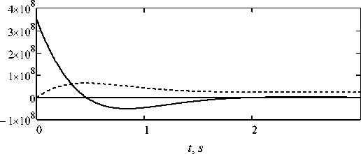
Fig. 2. The time responses of changes of pressure to controlling and to disturbing affecting
k ш ( t ) 5 2
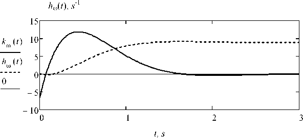
Fig. 3. The time responses of change of an angular velocity to controlling and disturbing affecting
Calculation of time responses of change of an angular velocity to controlling and disturbing affecting at Mnmax(t) = 14∙103 N ∙ m ko(t) = kou (t) + kom(t) • Mnmax(t), h(t) = hu (t) + hcom(t)'Mnmax(t).
The time responses of change of an angular velocity to controlling and disturbing affecting are presente nF g. 3.
Let's define system frequency responses on the channel of speed concerning control action. We will make change of a variable s = i ∙ ω. As a result of transformations, we will gain:
W ® u (s ) =
97,59 x - 97,59
-
2 ; W ® U (®) = 2 . .
s + 4,28 - s + 8,62 ® - 4,28 • i • ® - 8,62
We build a logarithmic amplitude–frequency response (LАFR) and a logarithmic phase frequency response (LPFR): frequency varies over the range ω = 0,1 – 100 s –1
180 π
L ®u (to) = 2 0l og (| ^ 6> u (®)| ) , Ф ® u (to) = a rg ( ^ co u (®) )
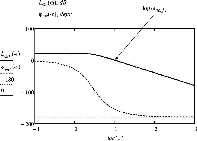
Fig. 4. Logarithmic frequency responses of system for the channel of control action – speed
Logarithmic frequency responses of dynamic system for the channel of control action – velocity are displayed on Fig. 4.
Crossover frequency: logЮ uc.f . = 0,992; Ю uc . f . = 10 0,992 = 9,83 radIs.
Vibration frequency of asphalt running rollers usually makes from f 1 = 30 Hz to f 2 = 70 Hz [4]. At a speed control of driving of a running roller vibration is a handicap. Values LАFR for this frequency range have made: L m u (2nf l ) =- 51,2 dB ; L m u (2nf 2 ) = - 65,9 dB .
At frequencies over the range from 30 Hz to 70 Hz influence of control action on speed is relaxed in hundreds and thousand times in relation to influence in crossover frequency.
Let’s define system frequency responses on the channel of speed concerning disturbing affecting, having made of a variable s = i ∙ ω
W ® m ( 5 ) =
- 0,00048591( 5 + 3,281) 5 2 + 4,28 - 5 + 8,62
W ® m (®)
0,00048591 - i - ® + 0,00159427071
- ® 2 + 4,28 - i - ® + 8,62
We construct a logarithmic amplitude and phase frequency responses: frequency ranges ω = 0,1 – 100 s –1
L 1®m (Ю) = 20log ( K irn m (®)| 14000 ) , ф 1® m (to) = a rg ( H |H m i®))— .
π
Logarithmic frequency responses of system on the channel disturbing affecting – velocity are presented in Fig. 5.
Crossover frequency: logω mc . f . = 0,89; ω mc . f = 10 , = 7,8 rad /s.
Values LАFR for this frequency range have made: L 1ω m (2π f 1) = - 28, 85 dB
L 1ω m (2π f 2) =- 36,21 dB .
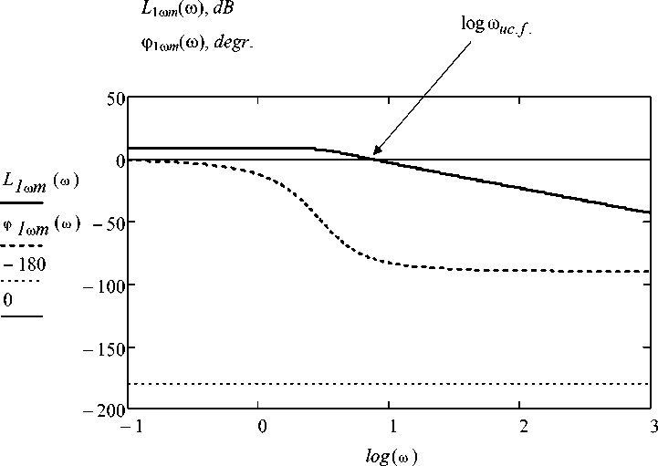
Fig. 5. Logarithmic frequency responses of system on the channel disturbing affecting – velocity
At vibration frequencies over the range from 30 Hz to 70 Hz moment influence vibration for the velocity is relaxed in tens and hundreds times in relation to influence of this moment in crossover frequency.
Conclusions
The problem of construction of mathematical model of control process by velocity of movement of an asphalt roller, taking into account dynamic responses of system of the volume hydraulic drive of transmission and a roller movement resistance on a rigid pavement is solved. Analytical methods of working out of mathematical model of a control system are applied. Results of research of the time responses and frequency responses on channels are gained: control action – velocity of motion; disturbing influence – velocity of motion.
At frequencies over the range from 30 Hz to 70 Hz that is characteristic for systems vibration running rollers, influence of control action on speed is relaxed in hundreds and thousand times in relation to influence in crossover frequency.
At vibration frequencies over the range from 30 Hz to 70 Hz moment influence vibration for the speed is relaxed in tens and hundreds times in relation to influence of this moment in crossover frequency.
The gained transfer functions can be used for research of dynamic responses of systems of the drive of a motion of the road roller and automatic-control system model building by working process of the vibration roller.
