The definite questions of simulation of transformable space structures dynamics

Author: Zikun Zhang, Zimin V.N., Krylov A.V., Churilin S.A.
Journal: Сибирский аэрокосмический журнал @vestnik-sibsau
Section: Авиационная и ракетно-космическая техника
Article in issue: 1 т.20, 2019.
Free access
This paper describes large transformable space structures with various configuration in the folded transport posi- tion and in the open working one. As an example, simulation of transformable space structures dynamics is shown for the antenna circuit foldable load-bearing frame with diameter of 5 m. For investigation of the foldable frame deploy- ment dynamics, a design scheme presented by a system of rigid bodies connected with each other by hinges is accepted as it is simple, but at the same time it considers features of the structure well enough. For performing stress analysis of the foldable frame elements during deployment, the frame shape at the certain time point of deployment, when relative velocities of adjacent elements are ultimate, is chosen. As a results of calculation using MSC.Adams software, positions, velocities and accelerations of the centres of mass of the foldable frame elements as well as the angular velocities and accelerations of the elements for each time step of the deployment are obtained. To perform stress analysis of the fold- able load-bearing frame, finite element model of the frame is developed using MSC.Patran/Nastran software. As a re- sults of investigation of stressed and deformed states of antenna circuit foldable frame elements both without taking into account damping and with consideration of damping, stresses arising in the foldable frame elements at the certain time points during deployment are found.
Transformable structures, deployable structures, dynamics, modeling, simulation, movement, configuration, model
Short address: https://sciup.org/148321898
IDR: 148321898 | UDC: 629.78:531.395 | DOI: 10.31772/2587-6066-2019-20-1-68-73
Некоторые аспекты моделирования динамики трансформируемых космических конструкций
Рассматриваются крупногабаритные трансформируемые космические конструкции, имеющие разные конфигурации в транспортном состоянии и рабочем положении. Моделирование динамики трансформируе- мых космических конструкций рассмотрено на примере складного несущего силового каркаса антенного контура диаметром 5 м. Для анализа динамики раскрытия принимается простая, достаточно хорошо учиты- вающая особенности конструкции расчетная схема в виде системы абсолютно твердых тел, связанных между собой шарнирными соединениями. В качестве расчетной схемы для определения напряженно- деформированного состояния элементов каркаса при раскрытии принимается его форма в определенный мо- мент времени, когда относительные скорости соседних элементов максимальны. В результате расчета в программном комплексе MSC.Adams получены координаты, скорости и ускорения центров масс элементов каркаса, а также их угловые скорости и ускорения. Для определения напряженно-деформированного состоя- ния каркаса в программном комплексе MSC.Patran/Nastran построена его конечно-элементная модель. В результате расчета напряженно-деформированного состояния элементов каркаса без учета и с учетом демпфирования получены значения возникающих в них напряжений в определенные моменты времени.
Text of the scientific article The definite questions of simulation of transformable space structures dynamics
Introduction. The intensive development of space technology poses the task of creating of fundamentally new large space structures [1; 2]. A necessary stage of their development is a preliminary investigation of the characteristics of both free and controlled such structures' motion by means of mathematical modeling of their dynamics.
Mathematical modeling of dynamics of such structures is a subject of wide research. The main methods of analysis of the mechanical behavior of large space structures are described in [3]. Transformable large space structures have different configurations in the transport state and in the operating position in orbit. As a rule, deployment of the developed transformable structures, is unique process for each considered system, however, in some cases it is possible to find a common way of modeling the dynamics of their deployment. A model that is simple but well enough considering the special features of structures consisting of tens, hundreds and even thousands elements interconnected by hinges is accepted as a design scheme [4–9]. System of differential equations of transformable structure elements motion is usually known as a model of dynamics of such structure, and a numerical solution of these equations is usually understood as the mathematical modeling of structure dynamics.
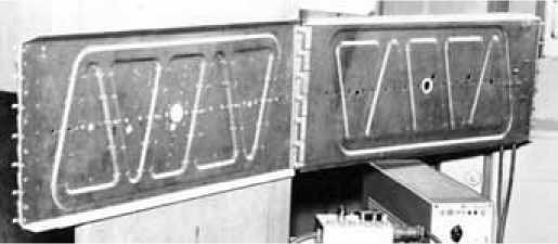
Calculation model for the analysis of the deployment of the circuit antenna frame. Among the large space structures, a special place is occupied by the multilink transformable circuit antennas, the load-bearing frame of which provides the minimal dimensions of the structure in the folded transport position and required rigidity of the structure in the unfolded working one (fig. 1). The frame consists of one-type elements connected by elastic hinges. The elements can be made of both metals and composite materials (fig. 2). The hinges contain one-sided stops to provide of deployment of the reflector into the opened working position, making desired shape of the reflecting surface its maintenance during operating life. Deployment of considered structures occurs automatically due to potential energy accumulated in the elastic elements of the hinges when the reflector had been being folded into the transport state. Computer modeling of steps of the multi-link load-bearing frame deployment gives us an opportunity to consider various schemes of this process and evaluate correctness of the technical solutions incorporated in the structure's scheme at the project level.

Fig. 1 . The spacecraft with circular transformable antennas with diameters of 20 m
Рис. 1. Космический корабль с трансформируемыми кольцевыми антеннами диаметром 20 м
а
Fig. 2. The elements of transformable space structures:
a – shaped rectangular panels; b – thin-walled quill rods of unidirectional carbon fiber reinforced polymer with longitudinal fibers orientation

b
Рис. 2. Элементы трансформируемых космических конструкций:
а – прямоугольные профилированные панели; б – тонкостенные трубчатые стержни из однонаправленного углепластика с продольным расположением волокон
The folding load-bearing frame consists of two packets of shaped rectangular panels 550 x 230 x 6 mm (13 panels per package) one side of which is pivotally connected with the spacecraft, and another side the same way is connected with short closing panel.
As a design scheme for studying of dynamics of the antenna folding frame deployment using MSC.Adams, a system of rigid bodies interconnected by hinges is accepted. At a certain relative position of the adjacent panels during the deployment, restrictions limiting mutual angular displacement of panels are applied to provide holding of the antenna frame in the operating unfolded position. The panels of the foldable antenna frame are connected with each other by external and internal hinges modeled by means of “axial joint” elements (Revolute Joint in terms of Adams software). Torsion springs in the hinges are modeled by means of elastic and dissipative elements with linear dependencies of the moments from the opening angles and the relative angular velocities of the panels (Torsion Spring in terms of Adams software), the stiffness coefficient, viscous resistance coefficient and preliminary angles of twist of the springs for which are given. The external and internal hinges have different preliminary angles of twist, which have been chosen the way to provide a circle shape of the folding load-bearing frame in the operating unfolded position.
The panels are modeled by rigid rectangular parallelepipeds with dimensions of 550 x 230 x 6 mm. The density of the equivalent material of the panels in Adams is chosen so that the mass of the simulated non-profiled panels is equal to the mass of the real profiled panels. The moments of inertia of the panels in Adams are taken equal to the moments of inertia of the real profiled panels.
Free ends of the panels placing in the base of the left and right packets are considered to be hinged.
The power characteristic of each of the elastic and dissipative elements modeling the torsion spring in the hinges [11–13] is determined by the following ratio
Mi (Ф,,
where c i is the stiffness coefficient of the i -th spring; ц i is the coefficient of viscous resistance of the i -th spring; P i is the current opening angle of adjacent panels; p tw i is the preliminary angle of twist of the i -th spring.
At a certain relative position of the adjacent panels when they are opening, and the opening angle p i reaches a certain value p stop i corresponding to operating position of panels, restrictions limiting the mutual angular displacement of the panels are applied to panels by the certain making of their hinges. Physically the restrictions are made as various stops, which are modeled by massless elastic and damping elements with nonlinear dependency of the moment from the opening angle and can be written as
P
i
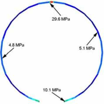
- stop, Pi- ^ Pstop, ’ i-th elastic if 0, Mstop/Pi, (pi) = ’ ■cstopi(P — Pstopi ) — ^stopiPi , if ’i —/ is the stiffness coefficient of the element; цstopi is the coefficient of viscous resistance of the i-th damping element; pstopi is value of the opening angle of adjacent panels, when the placing on the stop is getting; Pi is the relative angular velocity of the adjacent panels. When moving, adjacent panels can rotate towards each other and touch each other. The model contains stops preventing a contact between the panels. They are presented by massless elastic elements with nonlinear dependency of the moment from the opening angle Mcont/Pi) = < 4' — 0, ■c cont,(pi — Pconti), if Pi > Pconti if Pi^Pcont where cconti is the stiffness coefficient of the i-th elastic element; Pconti is value of the i-th opening angle, when the adjacent elements are in contact. As a result of calculations, dependencies of coordinates, speeds and accelerations of centres of mass of the load-bearing frame panels from time, as well as dependencies their angular speeds and accelerations from time were received. Analysis of stressed state of the frame elements. The stressed state of the elements of the load-bearing frame during its deployment is determined by the impact loads arising when the adjacent frame panels are placing on the stops. The impact loads are obtained from the analysis of the frame deployment dynamics using the MSC. Adams software. Simulation shows that the panels of the load-bearing frame are placed on the stops at the different time points. At each time point, various groups of panels in different places of the frame reach their stops. Several time points are chosen when relative velocities of the adjacent panels from the certain group are ultimate. To investigate the stressed state of the load-bearing frame panels during deployment, in MSC. Patran/Nastran software the frame shape at the selected moments is adopted as a design scheme. At each considered moment it is supposed that panels are placed on their stops and the structure behaves as an elastic rod with specified characteristics. This approach gives the safety margin, since the mobility of frame panels relative to each other leads to reduction of real stresses due to the loss of kinetic energy in the joints. Knowing value of the angular velocity of the hinged first panel of one of the packets and knowing values of the angular velocities of the other panels of the packet, the velocity field at the certain points of each panel of the packet is determined by the formula v n = v p + m x r , where vp is the speed of the poles, for which each joint on the antenna frame from the attachment base point to the short closing panel is consistently accepted; m is the angular velocity vector of the corresponding panel; r = rn — rp , rp is the radius vector of the pole, rn is the radius vector of the point, where the velocity is determined. The radius vectors are specified in the inertial frames of reference whose origins are located at the places of hinge fastening for each frame packet on a rigid base. Velocities of the opposite packets panels are taken equal in magnitude and opposite in direction. Thus, the opening of the frame occurs symmetrically. The angular velocities of the panels as well as the velocities of their centres of mass (hereinafter used to test calculation of velocities of the selected model points) obtained for each time step of the deployment calculation are exported from Adams to a certain file as a table. To find velocities of the model selected points from the dependency given above for each selected moment of time a C++ program was written. To perform stress analysis of the frame panels, finite element model of the frame was built using MSC.Patran/Nastran software. Analysis of the stressed and deformed state of antenna frame was carried out by means of Direct Transient Response analysis (SOL 109, study of transient process) both without taking into account damping and with consideration of damping. Each panel is divided into ten “beam” finite elements. In total, the model consists of 270 such elements. All finite elements including elements at the panel boundaries are rigidly connected to each other. The panels placed at the base of the left and right packet are considered to be clamped by their free ends. As a dynamic model of the folding frame the finite element model is accepted M u + D u + K u = P , where M,D,K are mass, damping and stiffness matrices respectively, P is the external loads vector, u is the vector of nodal displacements, it is the vector of nodal velocities. In our case P = 0 . Calculated values of velocities in the selected points of the frame model are taken as initial conditions for calculation of the transient process using MSC. Nastran software, that is, when t = 0: u (0) = u0, it (0) = it0, where u0, u0are vectors of the initial nodal displacements and velocities. In accordance with the recommendations presented in the MSC. Nastran user manuals, transient response analysis time integration step should be selected taking the conditions as at least ten steps per response period time for the maximal frequency of interest. Then, if we take into account first ten frequencies of natural oscillations of the antenna frame in the plane of deployment, in our case the time integration step will be equal to A t = T 10 • 9 Hz ® 0,01sec. At the same time, it is recommended to take the time integration step finding within At = 10-4...10-3 sec. interval, so to obtain more accurate stress values, the time integration step during the calculations was taken equal to At = 10-3 sec. Structural damping in Direct Transient Response analysis is taken into account by usage of the equivalent viscous damping. For the sinusoidal displacement response with constant amplitude, the structural damping force is constant and the viscous damping force is proportional to the frequency. For such a response, the two damping forces are equal at some frequency. Having done calculations without damping it was clear that the frequency of the structure oscillations under the impact had closed value to the second natural oscillations frequency in the plane of the opening of the frame. So the second natural oscillations frequency was chosen as a frequency of equivalence of structural damping and viscous one. As a results of investigation of stressed and deformed states of antenna circuit foldable frame elements both without taking into account damping and with consideration of damping, stresses arising in the foldable frame elements at the certain time points during deployment are found. Fig. 3 shows the stressed state of the antenna frame at the time point of t = 5.925 sec., when small stresses occur, looking all considered cases. The values of the stresses occurring in the panels are shown the same. a Fig. 3. Stressed state of the antenna frame at time point of t = 5.925 sec.: a – without consideration of damping; b – with consideration of damping b Рис. 3. Напряжения в момент времени t = 5,925 с.: a – без демпфирования; б – с демпфированием Conclusion. It is possible to reduce or even exclude impact loads during the process of uncontrolled deployment by reducing the initial potential energy of the springs, i.e. by changing the elastic characteristics of the spring elements included in the structure. At the same time, the angular velocities at the time of placing of adjacent structural elements on the stops will accordingly decrease. This will lead to decreasing of the velocities determining the magnitude of the impact impulse acting on the considered elastic transformable structure. However, this way is not always possible, since besides the smooth and reliable deployment of the transformable structures, it is necessary to guarantee their following operation in orbit. Therefore, in order to provide a controlled transformation of the system from the transport folded position to the operating opened one, it is necessary either to develop the structure with an additional cable synchronization system, or to replace the springs by operating drives. This will significantly complicate the structure and increase its mass. It is possible to create large transformable space structures in orbit, using for their deployment actuators made of materials with a shape memory effect [14; 15]. There are several types of actuators based on materials with shape memory effect. One of them can be called a one-dimensional direct-acting actuator, the another one – an actuator with aftereffect, which uses a spring or differential drive making an active retarding force and damping for creating force of actuator itself.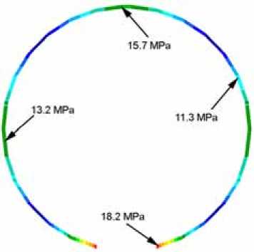
References The definite questions of simulation of transformable space structures dynamics
- Лопатин А. В., Рутковская М. А. Обзор конструкций современных трансформируемых космических антенн. Ч. 1 // Вестник СибГАУ. 2007. № 2(15). С. 51-57.
- Лопатин А. В., Рутковская М. А. Обзор конструкций современных трансформируемых космических антенн. Ч. 2 // Вестник СибГАУ. 2007. № 3(16). С. 78-81.
- Механика больших космических конструкций / Н. В. Баничук, И. И. Карпов, Д. М. Климов [и др.]. М.: Факториал, 1997. 302 с.
- Виттенбург Й. Динамика систем твердых тел. М.: Мир, 1980. 292 с.
- Бойков В. Г. Моделирование динамики механических систем в программном комплексе EULER // САПР и графика. 1998. № 1. С. 38-48.
