The evolution of the concept of a “small” aircraft and the development of its design

Author: Bobkov A.V., Mitashova T.A.
Journal: Siberian Aerospace Journal @vestnik-sibsau-en
Section: Aviation and spacecraft engineering
Article in issue: 1 vol.27, 2026.
Free access
This study analyzes the design features of small, aircraft-type unmanned aerial vehicles. The first stage of the study examined the chronology of the evolution of the concept of “small”. It was shown that this concept should be understood as a combination of two factors: small size and low flight speeds. Because of this, the boundary layer flow occurs in a laminar-turbulent transition regime. Due to boundary layer instability, a “laminar bubble” forms above the wing, reducing the lift properties of the vehicle. Reynolds numbers in the range of Re = 105…106 were proposed as an aerodynamic criterion for smallness. At speeds of 70–150 km/h, the mean aerodynamic chord size is in the range of baverage = 0.1–0.9 m. The second stage analyzed the influence of the “square-cube” law on the energy efficiency of the vehicle during the miniaturization of its design. According to this law, the specific wing loading and the (weight)1.5/power ratio are reduced by the magnitude of the reduction factor for the linear dimensions of the aircraft. This is interpreted in the article as a reduction in the efficiency of the aircraft, which converts the kinetic energy of the airflow into lift. When transporting a unit of weight over a unit of distance, a small aircraft consumes several times more fuel than a full-size aircraft. A potential way to increase energy efficiency is to reduce or eliminate the trim losses of lift. This reduction is achieved by reducing the area of the rear-mounted horizontal tail, and the elimination of this loss is achieved by replacing the standard aerodynamic configuration with alternatives: canard or tailless configurations. These configurations do not use a rear-mounted horizontal tail, which generates negative lift, requiring additional energy to compensate. At the 3rd stage of the study, recommendations were formulated for the developers of the considered class of devices: 1) small-sized devices have a naturally low aerodynamic and energy efficiency, increasing which to the level of full-size devices is practically impossible; 2) improving aerodynamics is possible through the use of special profiles, morphing wing technology and boundary layer control methods; 3) increasing the duration and range of flight is possible due to the reduction of balancing losses of lift, using a beam tail in a normal configuration or using alternative aerodynamic configurations; 4) the article presents a block diagram of the iterative process for determining the wing area, the value of which will satisfy the conditions of the balance of forces and moments for various values of the ratio of the wing and horizontal tail areas.
Small aircraft, aerodynamic quality, aerodynamic design, lift generation
Short address: https://sciup.org/148333272
IDR: 148333272 | UDC: 623.746.4-519 | DOI: 10.31772/2712-8970-2026-27-1-96-107
Text of the scientific article The evolution of the concept of a “small” aircraft and the development of its design
In recent years, the development of unmanned aerial vehicles (UAVs) has been driven by design miniaturization. Small aircraft-type unmanned aerial vehicles (SUAVs) are widely used in many sectors of the economy, particularly in geological exploration, agriculture, search and rescue operations, and elsewhere [1–3]. S. A. Cambone [4] presents an analysis of the development prospects for this class of aircraft in the coming years
In UAV classifications, the dimensionality of UAVs ranges from micro-sized devices weighing less than 25 g to tactical and strategic devices weighing up to 1.5–5 t [5; 6]. The classifications do not use the term “small” unmanned aerial vehicles of the aircraft type. Based on their performance characteristics, such devices are classified as small and tactical UAVs (the “light” UAV category).
Unmanned aerial vehicle developers, using the term “small” [7–10], do not specify the criteria for their identification or distinction from other classes of aircraft. The characteristics of small unmanned aerial vehicles (UAVs) are related to their aerodynamics and low Reynolds numbers [11–14].
Well-known studies in this area include the work of many domestic (O. G. Buzykin, A. V. Kazakov, A. V. Shustov, S. V. Serokhvostov, I. V. Voronich, S. A. Kolchev, D. V. Panchuk) and foreign authors (John D. Anderson Jr. [15], Jan Roskam [16], Fred Thomas [17], Daniel Raymer [18]), who note a decrease in the aerodynamic quality of small unmanned aerial vehicles (UAVs) due to a deterioration in their load-bearing capacity. Improving the energy efficiency of devices, which is defined as the specific work performed when moving a unit of mass of the device over a unit of distance, is a pressing issue.
SUAVs’ Aerodynamic Features
Small dimensions combined with low flight speeds determine the differences in the aerodynamics of the SUAVs – an increased role of viscous forces in the range of flight Reynolds numbers Re ≈ 105–106. For such values of Re , the flow regime in the boundary layer becomes unstable, transitioning from a laminar to a turbulent regime and back. As an illustration, Fig. 1, based on data from [19], presents a diagram of the boundary layer state, in which the friction coefficient C f serves as an identifier of the flow pattern.
The Reynolds number flow regime is a multifactorial parameter that depends on surface roughness, incoming flow turbulence, wing profile curvature and airframe geometry. At the same Re numbers, the flow in different devices can be laminar, turbulent, or laminar-turbulent transition. Of greatest interest is the section of the diagram in the range 5·104< Re < 107, which contains two regions: at the bottom is the steady laminar flow regime, and above is the turbulent one (see Fig. 1). Between them lies a region of laminar-turbulent transition, called the critical zone. Line AB is shown as one variant of the laminar-turbulent transition. At Re < 105, the flow is most likely laminar. At Re = 5·105, laminar flow tends to transition to turbulent flow with a noticeable increase in skin friction. At Re > 106, the flow regime usually becomes turbulent, in which the boundary layer is less prone to flow separation from the wing surface [12].
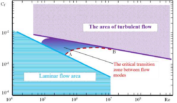
Рис. 1. Схема состояния пограничного слоя при изменении числа Рейнольдса
Fig. 1. Diagram of the boundary layer state with a change in the Reynolds number
At the leading edge of the wing, the boundary layer is laminar. At low Re values, it separates from the wing surface after a short distance, forming a so-called “laminar bubble”. It can be “short” (0.5– 1.0 % of the chord) or “long” (> 2 % of the chord) depending on the Reynolds number and the positive static pressure gradient [9]. In laminar flow mode, the bubble turns out to be “long” and stable, significantly distorting the shape of the wing profile and reducing the efficiency of lift generation.
During the laminar-turbulent transition, the laminar flow inside the bubble becomes turbulent, reducing its size to a “short” flow. After the bubble attaches to the flowing surface, the boundary layer approaches a turbulent regime [9]. In both cases, the bubble generates significant flow separation losses, which significantly exceed friction losses.
At Re ≈ 105–106, laminar effects (laminar boundary layer, bubbles, separations and laminar-turbulent transition) become natural causes of aerodynamic imperfections in the designs of small unmanned aerial vehicles with low aerodynamic quality.
Improving the flow regimes around the lifting surfaces of the aircraft-type small unmanned aerial vehicle is theoretically possible by “diverting” Re into the turbulent flow zone, for example, by increasing the flight speed [20; 21]. However, this triggers a mechanism for increasing the size and power of the aircraft, moving the design out of the small-size zone and losing its advantages: low effective dispersion area, compactness and mobility of the design, ease of takeoff and landing.
The “square-cube” law and miniaturization of the aircraft design
The “square-cube” law [22] involves the disproportionate scaling of the geometry and force parameters that affect the aerodynamics and energy efficiency of an aircraft. For example, if the linear dimensions of the aircraft are reduced by a factor of n , then the wing area S decreases by a factor of n 2, and the volume (weight G ) by a factor of n 3. This reduces the specific wing loading by a factor of n. At the same time, laminar effects significantly degrade the load-bearing properties of the structure. Flow separation from the wing surface reduces the vertical pressure difference, decreasing the lift coefficient [14].
C y
Compared to full-size aircraft, the aerodynamic efficiency K = y of small-sized aircraft is sig-Cx nificantly lower [13], where Cy and Cx are the lift and drag coefficients, respectively. A reduction in the maximum lift coefficient Cymax narrows the range of angles of attack at which the wing effectively generates lift.
The demand for this class of devices requires clarification of the criteria for the concept of “smallsized” and an analysis of possible directions for optimizing the appearance of the device, taking into account the natural aerodynamic imperfections of the aircraft – type small unmanned aerial vehicle.
Dimension assessment of the aircraft – type small unmanned aerial vehicle
To geometrically identify the small unmanned aerial vehicle, we will evaluate the influence of the Reynolds number on the aircraft's linear dimensions, specifically, the mean aerodynamic chord c ma . We will assume a cruising speed of V = 100 km/h (≈ 28 m/s), which is typical for this type of small unmanned aerial vehicle:
Re = V cma = 28 cma = 1,918 ⋅ 106 ⋅ c ν 1,46 ⋅ 10 - 5 ma
where v is the coefficient of kinematic viscosity of air, m2/s.
The table provides a comparative analysis of the interdependence of cma and Re, as well as their influence on the nature of the flow around the bearing surface.
In the speed range of V = 70–150 km/h and chord length cma = 0.1–0.9 m, the flow over the surface takes on the character of a laminar-turbulent transition. This combination of speed and chord length can be considered a criterion for classifying the aircraft as a small unmanned aerial vehicle.
The relationship between c ma and Re in the aircraft - a type of small unmanned aerial vehicle
|
c ma |
Re (at 100 km/h) |
The nature of the flow around the bearing surface |
Location of the flow regime relative to the critical zone |
|
< 0,3 m |
(5–5,75)⋅105 |
Separations and laminar bubbles predominate. Low aerodynamic quality |
Closer to the lower boundary of the critical zone |
|
(0,3–0,42) m |
(5,75–8)⋅105 |
Laminar-turbulent transition. The quality is noticeably lower than that of full-size aircraft |
Middle part of the critical zone |
|
(0,42–0,52) m |
8⋅105–106 |
The boundary layer is stable. The quality degradation is still noticeable |
Closer to the upper boundary of the critical zone |
|
≥ (0,52–0,7) m |
≥ 106 |
Quality is improving, but has not yet reached the levels of full-size aircraft |
Critical zone exit section |
Energy efficiency assessment
We consider the power consumption for the flight of the aircraft – a type of small unmanned aerial vehicle, designed according to a normal aerodynamic configuration, in which the rear-mounted horizontal tail (HT) generates lift Y ht.
When performing horizontal flight, the required power N of the engine of the aircraft – type small unmanned aerial vehicle – is spent on generating three components of the force field: thrust T , wing lift Y and wing lift Y ht (Fig. 2).
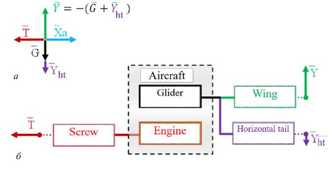
Рис. 2. Схема формирования силового поля ЛА СТ в горизонтальном полёте: а – силовой «крест» горизонтального полёта; б – элементы ЛА СТ, формирующие силовое поле
Fig. 2. Schematic diagram of the formation of the aircraft-type vehicle force field in horizontal flight:
a – force “cross” of horizontal flight; b – aircraft-type vehicle elements that form the force field
The condition of moment-force equilibrium of the apparatus has the form Y = G - Y ht = G + K\ ,
where in the associated coordinate system the modulus sign indicates a negative value Y ht .
From equation (2) it follows that the wing generates a lift force greater than the weight of the aircraft type vehicle, compensating for the negative lift force HT (see Fig. 2, а ). Miniaturization of aircraft design is accompanied by a fundamental physical limitation – the “square-cube” law, according to which the specific wing loading decreases. We analyze the efficiency of generating lift by an aircraft with a normal configuration as a converter of the kinetic energy of the air flow into lift.
We introduce the coefficient ks of the ratio of the wing and horizontal tail areas: ks = S ГО / S КР . The mechanism for generating lift for the wing and horizontal tail is the same and the formulas for calculating them are as follows [15; 18]:
Y = C yw • Sw • q , (3)
I Yh t\ = |C yh\• S ht • q = |C yht|• ks • S w • q , (4)
where С уw , С уht are the lift coefficients of the wing and the HT, respectively; q is the dynamic pressure.
Based on equations (2)–(4), we obtain the dependence of the wing area on the wing lift coefficients and HT:
S w
G q • (Cyw -|Cyht| • ks )
Substituting into (2) the expressions from (4) and (5), we find the dependence of Y on the weight G , the aerodynamic coefficients С уw , С уht and the ratio of the areas of the bearing surfaces k s :
Yw = G⋅
c yw
Cyw - I Cyht I ⋅ ks
From equation (6), the ratio of the lift force Y to the takeoff weight of the apparatus G will be equal to
Y = Cyw
Cyw - I Cyht I ⋅ ks
The numerator (7) characterizes the magnitude of the lift force taking into account compensation for balancing losses; the denominator does not take these losses into account.
We denote the relation G ⋅
c yw
c yw
-I Cyht I ⋅ ks
as the coefficient of balancing losses for the wing lift
force K wtl :
c yw
Cyw - I Cyht I ⋅ ks
This coefficient reflects the mechanism by which trim losses occur. In level flight, part of the lift is expended to compensate for the moment from the horizontal stabilizer (HT). In the denominator Cyw - I Cyht I ⋅ ks the difference characterizes the lifting force, which does not contain a compensatory component, I CУГО I ⋅ ks , the value of which depends on the lift coefficient of the HT and the ratio of the areas of the bearing surfaces.
For fixed aerodynamic coefficients С уw and С ht , the coefficient K wtl depends not only on the ratio of the wing and horizontal tail areas, but also on the lifting properties of the horizontal tail. In the tailless configuration ( k s = 0) and K wtl = 1. In the normal configuration ( k s > 0), the coefficient K wtl > 1. Figure 3 presents a comparative assessment of the effect of ks on the wing lift loss coefficient Kwtl . Typical aerodynamic coefficient values for this class of aircraft were used as fixed parameters: for the wing, С уw = 0.55, and for the horizontal tail, 2, the values I Cyht I = 0,4 and 0.8. The coefficient ks varied in the range k s = 0–0.25. Increasing the horizontal stabilizer area through increasing k s with a constant moment arm is accompanied by an increase in trim losses, and for a lift coefficient of С уht = 0.4, the relationship K wtl = f ( k s ) is nearly linear. Doubling the horizontal stabilizer's load-bearing capacity ( С уht = 0,8) is accompanied by a significant increase in trim losses, reaching 58 % for a horizontal stabilizer with an area of 0,25· S w .
Considering the large influence of the wing lift coefficients and the GT on the level of trim losses, we will find the equation for the relationship between the power N , weight G , Су and Сх , substituting into the formula N = X а ·V the drag force Х а = С х ·S w · 0,5ρ ·V 2 and the speed V from the formula:
2 ⋅ G 1,5 C
x
0,5 0,5 1,5
ρ ⋅ S C
C
In equation (9) the ratio x is considered as a criterion for maximum flight duration [15] or C 1 y ,5
1 C
“aerodynamic quality at ceiling”. We designate = x , by transforming equation (9) to the form λ C 1 y ,5
N
G 1,5

⋅λ
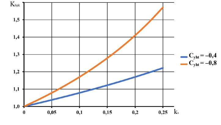
Рис. 3. Зависимость коэффициента балансировочных потерь от соотношения площадей крыла и горизонтального оперения
Fig. 3. Dependence of the balancing loss coefficient on the ratio of the wing and horizontal tail areas
The product (ρ· S )on the right-hand side of equation (10) represents the reduced mass of an air col-
ρ⋅S umn of unit height with a base area Sw, which interacts with the wing. Корень 2 w is a quantita- tive measure of the coefficient of maximum flight duration λ. The value ρ ⋅2 w characterizes aero-
ρ⋅ Sw ⋅λ , the
dynamic efficiency, the wing uses air to create lift. The higher the value of the product more air is involved in the process of generating lift, minimizing the power N. The result is savings in engine working fluid and an increase in the duration of the flight in cruising mode [15].
We consider the influence of the “square-cube” law on the nature of change G 1,5/ N . If the design miniaturization coefficient is n , then the reduction in speed V will be n times under the condition that С у = const. The power N will decrease by n 3,5 times, and the ratio G 1,5/ N will decrease by ( n 3)1,5/ n 3,5 times, i.e. by n times. Conclusion: The G 1,5/ N ratio for fixed-wing aircraft should be considered as a parameter that accounts for the impact of scale on the efficiency of power-to-lift conversion. As the aircraft's linear dimensions decrease, the G 1,5/ N ratio decreases proportionally to the miniaturization factor. A decrease in G 1,5/ N reduces the range or endurance per unit of fuel (battery) mass. In Anderson's work [15] it is directly stated that the condition for maximum flight duration is the maximum value mode λ.
kg and corresponds m
The dimension of the ratio G1,5/N is equal to the square root of the fraction to the linear density ρL, where ρL = m/L, m is the mass of a body with length L. For an aircraft, the linear density means the mass per unit of characteristic linear dimension – the wingspan Lw, i.e.
m
ρ L \L
.
w
The G 1,5/ N ratio can be considered a scale-based criterion, linking mass, geometry, and power requirements. It has the dimensions of linear density, increases with mass at a fixed span, and reflects the scale-based limitations of small, aircraft-type unmanned aerial vehicles.
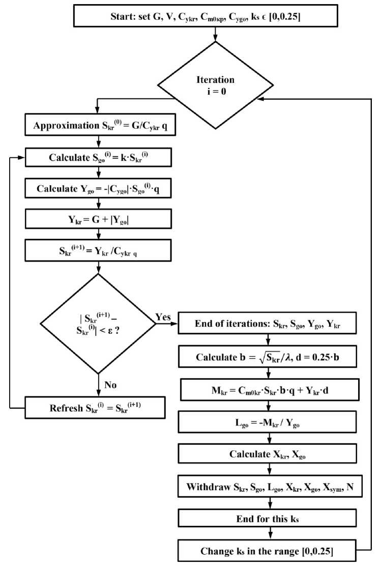
Рис. 4. Блок-схема расчёта площади крыла Sкр
Fig. 4. Flow chart for calculating the wing area Sw
Features of the formation of the appearance of small unmanned aerial vehicles of the aircraft type
The aircraft's appearance includes general design features: geometric dimensions, aerodynamic configuration, engine, onboard equipment and payload arrangement, as well as operational requirements—takeoff and landing method, transportability of the structure, etc.
The design of small unmanned aerial vehicles of the aircraft type can be divided into two dimensional zones based on aerodynamic parameters:
-
1) cma < 0,3 m. At speeds below 70 km/h, the boundary layer becomes laminar. Aerodynamic imperfections in the design are inevitable and practically difficult to correct;
-
2) cma = 0,3–0,9m is laminar-turbulent transition regime. At speeds of 70–150 km/h, such aircraft sizes are already large enough to carry a functionally acceptable payload, but their aerodynamic imperfections remain significant and can be reduced. In a study on the aerodynamics of small aircraft [19], such small unmanned aerial vehicles of the aircraft type are identified as the most interesting objects from a design perspective.
When developing the design of small-sized aircraft-type devices, it is advisable to take into account the following limitations, due to the characteristics of small unmanned aerial vehicles of the aircraft type.
Aerodynamics. In small, unmanned aircraft-type aerial vehicles, it is undesirable to use lifting surface profiles for turbulent flows. In such vehicles, such profiles will inevitably "separate".
Lift generation. The reduction in structural load-bearing capacity, as well as the reduction in specific power of the power plant of a small aircraft, require an informed decision on the area and magnitude of the specific wing loading .
Figure 4 shows a block diagram of the iterative process for determining the wing area Sw , satisfying the conditions of the balance of forces and moments for different values of the coefficient ks in the range [0, 0.25].
The wing area Sw is specified taking into account the interaction between the wing and horizontal tail. In addition to the force balance, the moment for ensuring longitudinal stability is taken into account. The calculation is performed for given values of the coefficient k s , which allows for selecting the optimal option based on the power criterion.
Conclusion
-
1. The reduction in aerodynamic quality and energy efficiency of small unmanned aerial vehicles of the aircraft type
-
2. There is potential for design optimization of small unmanned aerial vehicles of the aircraft type. However, radically optimizing the design to the level of full-size aircraft is problematic.
-
3. An analysis of the power balance N allows us to indicate the following relationship between factors: small size, energy efficiency, and design functionality of small unmanned aerial vehicles of the aircraft type:
are natural consequences of design miniaturization and the manifestation of the "square-cube" law. Optimizing the design of small unmanned aerial vehicles of the aircraft type to the level of full-size aircraft is virtually impossible, as the causes of their aerodynamic and energy imperfections are natural and unavoidable.
-
а) the low Re number and aerodynamic imperfections of the design should be perceived as a given and a natural manifestation of small dimensions;
-
b) the energy intensity of flight (required power) is estimated by the ratio G 1,5/ N and depends on the lift generation parameters of the wing and horizontal tail, as well as the ratio of their areas. These parameters should be set based on the functional purpose and acceptable energy efficiency of small unmanned aerial vehicles of the aircraft type;
-
c) to increase lift properties, it is necessary to enhance boundary layer stability by using special wing profiles designed for low Reynolds numbers, and boundary layer control methods such as injection, suction, and turbulence [22];
-
d) When using a normal aerodynamic configuration, reduce the magnitude of the horizontal tail's negative lift by increasing its moment arm. Theoretically, in such a configuration, the horizontal tail can also generate positive lift. In practice, given the thermal activity of low-altitude air flows, turbulence, or wind loads, this is difficult to achieve;
-
e) it is advisable to reduce balancing energy losses to zero by using alternative aerodynamic balancing schemes: "duck", "tailless", tandem;
-
f) at the stage of forming the design of the apparatus, it is necessary to evaluate the energy efficiency of generating lift using the ratio of the take-off weight and the required power of the type G 1,5 /N.
Acknowledgments. This work was supported by the Ministry of Education and Science of Khabarovsk Krai, Agreement No. 105c/2024, and the Russian Science Foundation, Project No. 242920111.
