The feature of raising the “Express-AMU3” and “Express-AMU7” satellites into geostationary orbit

Author: Yu. M. Ermoshkin, A. A. Vnukov, D. V. Volkov, Yu. V. Kochev, R. S. Simanov, E. N. Yakimov, S. Yu. Pridannikov
Journal: Siberian Aerospace Journal @vestnik-sibsau-en
Section: Aviation and spacecraft engineering
Article in issue: 4 vol.23, 2022.
Free access
At present, in order to increase the launch mass, raising satellites into geostationary orbit by their own propulsion subsystem is widely used. Oly the JSC “Academician M. F. Reshetnev “Information Satellite Systems” applied such a scheme for several satellites of their own design - "Express-AM5", "Express-AM6", "Express-80" and "Express-103". Along with this, some diversity of approaches to the implementa-tion of this operation can be noted. In particular, the orbit raising of the above satellites was carried out using the onboard propulsion subsystem based on SPT-100 plasma thrusters. The operation was carried out by one or two thrusters. The use of two thrusters of the "Express-80" and"Express-103" satellites was due to the desire to keep within a reasonable amount of no more than six months with a significant increase in the output mass. Nevertheless, the duration of the orbit raising of about 150 days, which took place dur-ing the raising of satellite data, is also excessively long. It is evidemnt that it can be reduced, other things being equal, only by increasing the available thrust of the thrusters. This can be achieved both by increas-ing the thrust of individual units, and by increasing the number of simultaneously used thrusters. Therefore, for the new Express-AMU3 and Express-AMU7 satellites (with dimensions similar to the Express-80 and Express-103 satellites), for which a paired launch was also assumed, both of these methods were used. For orbit raising, two SPT-100V thrusters and, additionally, an SPT-140D type thruster were used. The total thrust of a cluster of thrusters made it possible to count on a significant reduction in the duration of orbit raising in comparison with the Express-80 and Express-103 satellites. The SPT-140 thruster developed by JSC "Experimental Design Bureau FAKEL" was used in Russia for the first time. For its power supply, the CCS-140D control and conversion device was specially created at the JSC "Design Bureau Polyus". The use of a combination of three thrusters made it possible to significantly reduce the duration of the opera-tion of raising into geostationary orbit.
Plasma thruster, satellite, orbit raising, power processing unit, orbit control
Short address: https://sciup.org/148329662
IDR: 148329662 | UDC: 621.455 | DOI: 10.31772/2712-8970-2022-23-4-696-707
Text of the scientific article The feature of raising the “Express-AMU3” and “Express-AMU7” satellites into geostationary orbit
At present, raising a satellite into geostationary orbit has become almost a routine operation. Thus, only the JSC “Academician M. F. Reshetnev “Information Satellite Systems” applied it for several satellites of its own design - "Express-AM5", "Express-AM6", "Express-80" and "Express-103". As noted earlier, the main effects of using additional orbit raising are the following: a) reduction of launch costs by approximately half during a paired launch of a satellite, since one launch vehicle is used; b) an increase of the mass of a satellite brought to the geostationary orbit [1]. Thus, useful effect for the Express-AM5 satellite was approximately 110 kg with the orbit raising of 67 days by one thruster of the SPT-100V type with the thrust of 83 mN; for the Express-80 satellite - about 380 kg with the duration of 149 days by two SPT-100V thrusters [1]. The use of two thrusters was caused by the endeavor to keep within the time of orbit raising into a reasonable amount of no more than six months with a significant increase in the throw-weight. The duration of orbit raising by one thruster in the latter case would be about a year, which is clearly unacceptable for a consumer. Nevertherless, the duration of about 150 days is also excessively long. It is evident that the duration of orbit raising can be reduced (all other conditions being equal) only by increasing the available thrust of the engines. This can be achieved both by increasing the thrust of individual modules, and by increasing the number of thrusters being used simultaneously. Therefore, for the new Express-AMU3 and Express-AMU7 satellites (with the dimensions similar to the Express-80 and Express-103 satellites), for which a paired launch was also assumed, both of these methods were used. For orbit raising, two SPT-100V thrusters were used in the mode with a nominal thrust increased to 90–91 mN similar to the Express-80, Express-103 satellites and, additionally, an SPT-140D type thruster with a nominal thrust of 290 mN with a power of 4.5 kW (3 kW in reduced power mode). Thus, the total thrust of the engine bundle in the nominal mode was about 470 mN, which made it possible to count on a significant reduction in the duration of orbit raising in comparison with the Express-80, Express-103 satellite. The SPT-140 thruster developed by the JSC "Experimental Design Bureau FAKEL" was previously qualified for use on Western satellites [2]; and in the dual-mode SPT-140D version, a Western-made satellite, for example, Eutel-sat-172B [3], is used. 60 SPT-140 type thrusters for 15 foreign satrllites have a flight history, which are used for raising into the GEO and subsequent orbit correction. The duration of the orbit raising of a satellite varied from 2.5 to 6 months with the simultaneous operation of two or three SPTs-140 depending on the mass and power of spacecraft. In Russia, such a thruster was used for the first time. For its power supply, the CCS (conversion and control system)-140D device was specially created at the JSC "Design Bureau Polyus".
It should be noted that the Hall motors with a power of about 5 kW were developed as in Russia and in the world quite intensively. At the Experimental Design Bureau "Fakel", much attention was paid to the study of the SPT-140D operation modes both during ground tests and during flight operation as part of Western spacecraft [4]. JSC Keldysh Research Center created a sample of the KM-7 thruster capable of operating in the range of 3.5–6 kW [5]. Abroad, the 4.5 kW BHT-4000/XR-5 thruster (Aerojet, USA), which was an analogue of the Russian SPT-140, was used to raise AEHF satellite into the orbit in 2011 [6]. In Europe and America, work on powerful thrusters from 5 kW and higher is being carried out on a wide front [7–12].
Conversion and control devices for thrusters with a power of about 5 kW were developed both in the USA and Europe, for example, the PPU Mk3 device manufactured by TAS-B (Belgium) [13], as well as the devices from the European concern ADS [14], are known.
Historically, the SPT-140/SPT-140D thruster was created quite a long time ago, but it was not in demand for domestic satellites due to excess power in relation to orbit correction tasks. Only with the increasing urgency of the task to raise a satellite of increased mass into the GSO and the desire to minimize the duration of this stage, the SPT-140D thruster found its application on Russian satellites.
This work highlights the features of the development and application of the subsystem for orbit raising and orbit correction of the Express-AMU3, Express-AMU7 satellite using the SPT-140D and CCS-140D thusters.
The composition of the thruster subsystem of correction and orbit raising. Choosing the type of thrusters, their layout on a satellite
The propulsion subsystem for the tasks of orbit raising and orbit correction includes six correction units based on the SPT-100V thruster, created at the JSC "Experimental Design Bureau Fakel", Russia (Fig. 1, 2), one orbit raising correction unit based on the SPT-140D thruster (JSC "Experimental Design Bureau Fakel") (Fig. 3), as well as a gas distribution unit (Fig. 4), three PPU-Mk2 devices and six FU filtration units (TAS-B, Belgium) (Fig. 5, 6), one CCS-140D device with a power filter (JSC "Design Bureau Polyus") (Fig. 7, 8), xenon supply unit (JSC “Academician M. F. Reshetnev “Information Satellite Systems”) (Fig. 9), xenon high pressure tank (JSC “Academician M. F. Reshetnev “Information Satellite Systems”) (Fig. 10).
As on the Express-80 and Express-103 satellites, blocks were used for orbit raising. These blocks consist of a SPT-100V thruster and a gas distribution unit (GDU) in a vertical layout, in which the thruster was installed on the GDU (Fig. 1).
To correct the orbit, units in the horizontal layout were used (Fig. 2). A characteristic feature of the orbit raising unit based on the SPT-140D thruster was a separate design of the cathodes and the xenon flow controller, which were installed on separate seats in the immediate vicinity of the thruster (Fig. 3, 4).
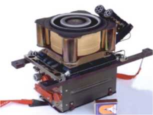
Рис. 1. Блок коррекции довыведения на базе СПД-100В
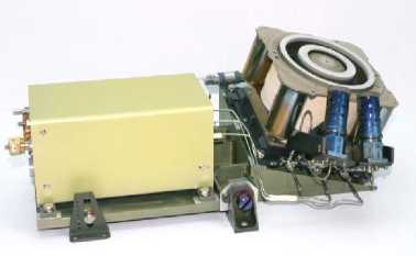
Рис. 2. Блок коррекции орбиты на базе СПД-100В
Fig. 1. Orbit raising thruster unit on the base of SPT-100B
Fig. 2. Orbit control thruster unit on the base of SPT-100B
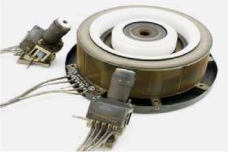
Рис. 3. Двигатель довыведения СПД-140Д с катодами
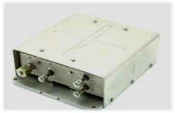
Рис. 4. Блок газораспределения для двигателя СПД-140Д
Fig. 3. Orbit raising thruster SPT-140D with cathodes
Fig. 4. Xenon flow controller for SPT-140D
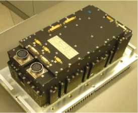
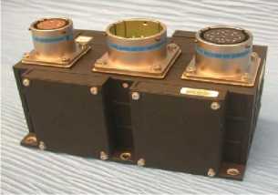
Рис. 5. Прибор PPU-Mk2
Рис. 6. Блок фильтрации FU
Fig. 5. PPU-Mk2 unit
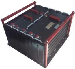
Fig. 6. Filter unit
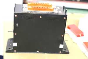
Рис. 7. Устройство управления и питания СПУ-140Д
Рис. 8. Фильтр питания СПУ-140Д
Fig. 7. Power and control unit of CCS-140D
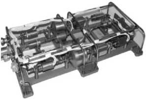
Fig. 8. Supply filter of CCS-140D
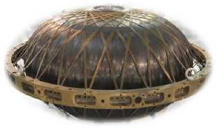
Рис. 9. Блок подачи ксенона
Fig. 9. Xenon feed unit
Рис. 10. Ксеноновый бак высокого давления
-
Fig. 10. High pressure xenon tank
These units (except for the PPU, FU, CCS and power filter units) were combined into a system by inter-unit pipelines according to the scheme shown in fig. 11. All the thrusters were powered by the working fluid from a common tank. To reduce the pressure of the working fluid to the required pressure at the thruster inlet, single two-channel xenon supply unit was used, which provided the total flow of the working fluid through three simultaneously operating orbit raising thrusters.
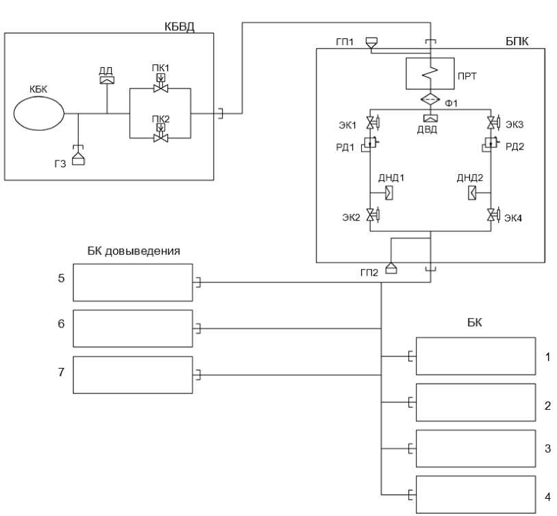
Рис. 11. Функциональная схема двигательной подсистемы:
КБВД – ксеноновый бак высокого давления; БПК – блок подачи ксенона; БК – блоки коррекции;
ГЗ – горловина заправочная; ГП – горловина проверочная; ДВД – датчик высокого давления; ДНД – датчик низкого давления; ДД – датчик давления; КБК – корпус баллона композитного; ПК – пироклапан;
ПРТ – подогреватель рабочего тела; РД – редуктор давления; Ф – фильтр; ЭК – электроклапан
-
Fig. 11. Propulsion subsystem functional scheme
HPXT – high pressure xenon tank; XSU – xenon supply unit; CB – correction blocks;
FN – filler neck; TF – test filler; HPS – high pressure sensor; LPS – low pressure sensor; PS – pressure sensor; CCB – composite cylinder body; PV – pyro valve;
AFH – astuation fluid heater; PR – pressure reducer; F – filter; EV – electrovalve
As on the Express-80 and Express-103 satellites, on the Express-AMU3 and Ex-press-AMU7 satellites, the concept of separate use of thrusters for orbit raising and subsequent orbit correction was adopted. The thrusters were fixed on the body of the satellite motionlessly. The thrusters 1–4 are used to correct the longitude and inclination of the orbit, and the thrusters 5–7 are used for the orbit raising operation (Fig. 12). The advantage of this concept is that there are practically no thrust losses in the thrusters due to the small deviation of their axes from the required direction. Another advantage is that, taking into account the significant scale of the orbit raising operation in terms of the magnitude of the generated total impulse, the resource of the orbit correction thrusters is not consumed. The fixed attachment of the thrusters makes it possible to refuse a rather complicated thrust vector control system using drives or manipulators and thereby reduce the mass of the satellite platform structure.
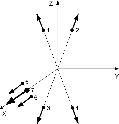
Рис. 12. Расположение блоков коррекции по осям связанной системы координат (Х – по радиус-вектору, Y – по вектору скорости, Z – на Север): 1–4 – двигатели коррекции орбиты, 5–7 – двигатели довыведения
Fig. 12. Thruster units allocation along the axes of the related coordinate system (X – along the radius vector, Y – along to velocity vector, Z – to North): 1–4 – orbit control thrusters, 5–7 orbit raising thrusters
Orbit raising thrusters, due to their significant total thrust, can also be used for accelerated transfer of the satellite to another point in the geostationary orbit or insertion into a disposal orbit.
Operating modes of thrusters. Supplying thrusters with working fluid and electricity. Thruster control scheme.
As before, on the Express-80 and Express-103 satellites, the SPT-100V thrusters were used in the mode of increased power and thrust within the control limits of the output parameters of the PPU-Mk2 devices. Compared to the nominal mode, thrust increased by about 10%, efficiency - by 4%, power -by 13%.
On the Express-AMU7 satellite, the SPT-140 thruster was used in the nominal power mode of 4.5 kW, and on the Express-AMU3 satellite, at a reduced power (3 kW), in order to test this mode to ensure orbit correction of a promising satellite.
To power three thrusters, it was necessary to ensure the flow of the working fluid through the xenon supply unit at a level of about 30 mg/s. For this, a specially developed modification of the xenon supply unit with an increased flow rate through the reducer was used.
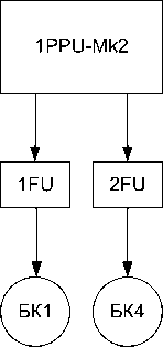
To solve the tasks of orbit raising and correction of the orbit, the power supply circuit for the correction units was chosen, which involves the use of three PPU-Mk2 devices, six FU filtration units and one PPU-140D, as part of a control and transformation unit and a power filter (Fig. 13).
We chose the scheme (Fig. 13) based on the capabilities of the PPU-Mk2 to control one of the two correction units using the built-in internal thruster switch (Thruster switch unit - TSU) similarly to the scheme used for the Express-80 and Express-103 satellites.
Thruster corrector control with SPT-140D was carried out according to the scheme: one thruster -one conversion and control system. The CCS-140D device was designed in a simplified single-channel non-redundant version, as it was supposed to be used for a limited time interval (the orbit raising section was planned to be about 1% of the satelliteservice life). It was possible to power the thruster with a consumption of 4.5 and 3 kW. The circuits were switched only when the cathode was selected. The remaining circuits were made without switching.
СПУ-140Д
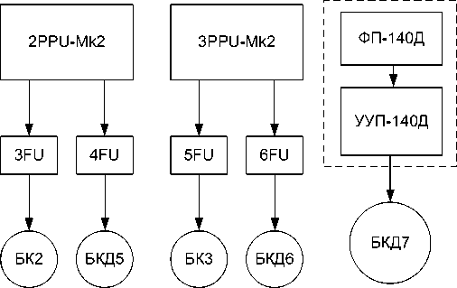
Рис. 13. Реализованная схема запитки блоков двигательной подсистемы коррекции
Fig. 13. Implemented scheme of the thruster units feeding
Propulsion subsystem control from on-board software
Taking into account the thruster start automation implemented in the PPU Mk2 devices, the software of the propulsion subsystem in relation to the PPU and SPT-100V carried out only control and some auxiliary functions, which included:
-
– entering into the PPU a setting of 5A for current, 306 V for discharge voltage, 12 A for cathode filament current;
-
– reading the values of telemetry parameters;
-
– issuing commands to form the PPU modes;
-
– shutting down the PPU and thrusters in abnormal situations;
-
– generating statistical and diagnostic reports.
To control the SPT-140D and CCS-140D thrusters, a different approach was used: taking into account the simplified design of the device, the start and control of the device and thruster were carried out using a separate specially developed on-board program. The tasks of this program included the implementation of the launch sequence diagram, as well as the control of the thruster parameters and CCS in the process of operation, and the generation of reporting information.
In accordance with with the adopted technology, this version of basic software of the thruster subsystem for orbit raising and correction has passed a full cycle of autonomous and integrated testing, as well as verification at the stage of electrical testing of the satellite.
Propulsion subsystem integration
Taking into account the fact that the composition and power consumption of the propulsion subsystem of the Express-AMU3 and Express-AMU7 satellites differed significantly from the prototypes, a necessary step was to check the joint performance of the components of the propulsion subsystem when the thrusters were actually turned on (subsystem integration). Tests were traditionally carried out at the JSC “Academician M. F. Reshetnev at the workplace of fire tests in a vacuum chamber with a volume of 80 m3, a brief description of which was given in [1].
The allocation of orbit raising thrusters in the vacuum chamber was taken similar to the regular allocaton (Fig. 14): SPT-140D was installed in the center; SPT-100V was on both sides from it.
Simultaneous operation of three orbit raising thrusters is shown in fig. 15.
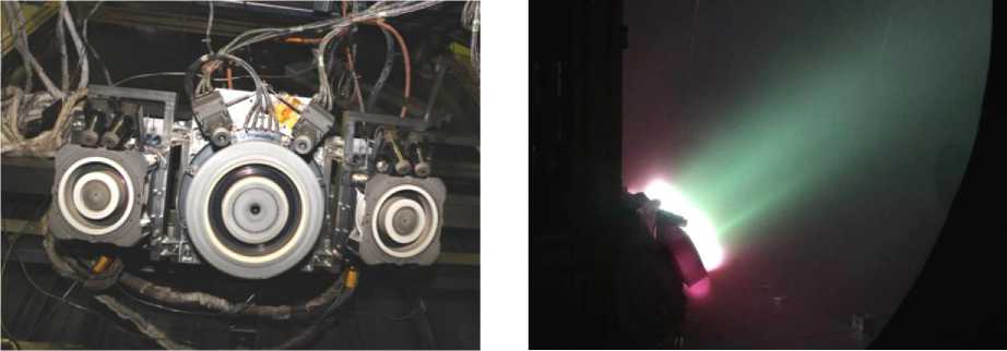
Рис. 14. Размещение двигателей коррекции довыведения при огневых испытаниях в вакуумной камере
Fig. 14. Orbit raising thrusters allocation during firing integration test in the vacuum chamber
Рис. 15. Одновременная работа трех двигателей довыведения
Fig. 15. Simultaneous action of the three orbit raising thrusters
Taking into account the difficulty of organizing the simultaneous start of three thrusters, sequential switching on and off of the thruster was provided.
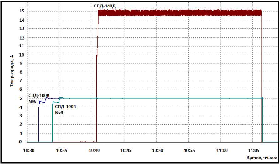
Рис. 16. Графики тока разряда СПД-100В и СПД-140Д
Fig. 16. The discharge current diagrams of the SPT-100B and SPT-140D
During integration tests, compatibility with the satellite power supply system was demonstrated. The work of the propulsion subsystem of orbit raising under the control of the onboard software was confirmed at the stage of the electrical tests of the satellite.
Test runs
After the separation from the upper stage and the construction of the standard triaxial orientation of the satellite, test runs of the orbit raising thrusters were carried out. The operation of the SPT-140D was confirmed both in the nominal mode of 4.5 kW (Express-AMU7) and in the reduced power mode of 3 kW (Express-AMU7). The expected thrust in low power mode, according to the preliminary data, was supposed to be reduced by about 30%. The total thrust of the three booster thrusters on the Ex-press-AMU3 satellite, according to estimates, was supposed to be approximately 80% of the nominal one.
Performing an orbit raising maneuver
Each satellite was filled with xenon in accordance with the accepted practice up to the full capacity of the tank - 300 kg.
The launch into a geotransfer elliptical orbit was carried out on the 13th of December, 2021. The parameters of the geotransfer orbit have not been officially published. Taking into account the fact that the launch was carried out by the same means as the Express-80 and Express-103 satellites (the Proton-M launch vehicle and the Breeze-M upper stage), the masses of the satellites were almost the same, it can be assumed that the parameters of the geotransfer orbit turned out to be close to the corresponding parameters of the Express-80 and Express-103 satellites [1].
The orbit raising was carried out similarly to the Express-80 and Express-103 satellites according to the modified Spitzer scheme, in accordance with the patent of the JSC “Academician M. F. Resh-etnev “Information Satellite Systems” [15], and consisted in correcting the orbit eccentricity with simultaneous correction of the orbit period in order to organize the drift of the satellite into the working point on the GSO. Nevertheless, in contrast to the orbit raising of the Express-80 and Express-103 satellites, the orbit raising of the Express-AMU3 and Express-AMU7 satellites in order to reduce the maneuver time was carried out not with a passive evolution of the orbit inclination, but with its active correction, for which additional sessions of thruster operation were carried out in the process of finalization.
The orbit raising of the Express-AMU7 satellite, combined with bringing the satellite to its operating point at GSO 145.0° E, was carried out in 86 days. Thus, the orbit raising time compared to the Express-80 and Express-103 satellites decreased by about 1.7 times, which can be considered a significant result. 105.6 kg of Xenon was spent. The estimates of the thrust value of a bunch of three thrusters based on measurements of the current parameters of the orbit showed the value of 457 mN. Excluding the thrust of two SPTs-100V (180 mN in the mode of 5 A discharge current), the thrust of the SPT-140D in the power mode of 4.5 kW was 277 mN (95.5% of the nominal value). The operating time of SPT-140D during the orbit raising was 992 hours with 117 impulses.
The orbit raising of the Express-AMU3 satellite, combined with bringing it to the operating point on the GSO at 103.0° E, was carried out in 101 days. Thus, the orbit raising time compared to the Express-80 and Express-103 satellites decreased by about 1.5 times. 105.6 kg of Xenon was spent.The measurements of the orbital parameters showed the value of the thrust of the thruster bundle of 380 mN (83% of the thrust on the Express-AMU7), which approximately corresponds to the expected value, taking into account the operating mode of the SPT-140D. The thrust of the SPT-140D at a power level of 3 kW was about 200 mN (69% of the nominal value) according to measurements of the orbital parameters. The operating time of SPD-140T was 1304 hours with 147 impulses.
Conclusion
The presented materials allow us to conclude the following.
-
1. For the first time in Russia, a combination of three thrusters were used to raise satellites into geostationary orbit: two SPTs-100V and one SPT-140D. For the first time in Russia, an SPT-140D high-
- power thruster with a nominal thrust of 290 mN, as well as an CCS-140D control device, were used as part of a satellitet and received a flight qualification.
-
2. The cycle of ground experimental testing was completed, including fire acceptance tests of the after-launch thrusters together with the PPU-mk2 and CCS-140D control devicesand a xenon supply unit designed to supply an increased gas flow. The compatibility with the satellite power supply system is shown.
-
3. The orbit raising maneuver for the Express-AMU-3 and Express-AMU-7 satellites was successfully completed. The total thrust of the cluster of three thrusters according to the results of trajectory measurements for the Express-AMU-7 satellite was 457 mN (97% of the nominal), which made it possible to reduce the duration of the orbit raising operation to a completely acceptable value - 86 days, i.e. 1.7 times less than the "Express-80"and "Express-103" satellites. Thus, the problem of a significant reduction in the duration of the orbit raising operation has been solved, which makes it possible to promptly put a satellite into regular operation with a significant increase in the mass of a satellite compared to the direct injection option. The xenon consumption during the orbit raising on the Ex-press-AMU-7 satellite was 105.6 kg, on the Express-AMU-3 - 124 kg.
-
4. Experimentally in full-scale conditions, the operating mode of the SPT-140D was tested at a power level of 3 kW. The possibility of long-term stable operation of the thruster and CCS in this mode is shown. The total thrust of three thrusters on the Express-AMU-3 satellite amounted to 380 mN (83% of the nominal), while the duration of the operation increased insignificantly compared to the Express-AMU-7 - up to 101 days (by about 17%). The orbit raising mode with reduced thrust and thruster power can be used for a satellite of reduced dimension with limited available power of the onboard power supply system, as well as in the satellite orbit correction mode after completion of the orbit raising stage, when increased thrust is not required.
References The feature of raising the “Express-AMU3” and “Express-AMU7” satellites into geostationary orbit
- Ermoshkin Yu. M., Vnukov A. A., Volkov D. V. et al. [Application of the propulsion subsystem based on the SPD-100V plasma engine for the additional ascent and correction of the orbit of the Ex-press-80 and Express-103 spacecraft]. Siberian Aerospace Journal. 2021, Vol. 22, No. 3, P. 480–493 (In Russ.). Doi: 10.31772/2712-8970-2021-22-3-480-493.
- Qualification of the SPT-140 for use on western Spacecraft / J. Delgado, R. Corey, V. Murashko, A. Koryakin, S. Pridannikov. AIAA-2014-3606, 50th Joint Propulsion Conference, Cleveland, Ohio, 2014, USA, July 28–30. 13 p.
- Casaregola C. Electric Propulsion for Station Keeping and Electric Orbit Raising on Eutelsat Platform. Joint Conference of 30th ISTS, 34th IEPC, 6th NSAT, Kobe-Hyogo, Japan, July 4–10, 2015, IEPC-2015-97. 6 p
- Komarov A., Pridannikov S., Lenguito G. Typical transient phenomena of Hall Effect thrusters. IEPC-2019-304. Proc. of the 36th International Electric Propulsion Conference, Vienna, Austria, 2019. 10 p.
- Lovtsov A. S., Selivanov M. Yu., Tomilin D. A. et al. [Main results of developments by the Keldysh Center in the field of electric propulsion systems]. Izvestiya RAN. Energy. 2020, No. 2, P. 1–13 (In Russ.).
- 30 years of Electric Propulsion Flight Experience at Aerojet Rocketdyne / W. Hoskins, R. Cas-sady, R. Myers et al. 33rd international Electric Propulsion Conference, The George Washington Uni-versity, Washington, D.C., USA, October 6-11, 2013. IEPC-2013-439. 12 p.
- Duchemin O., Rabin J., Balika L. et al. Qualification Status of the PPS-5000 Hall Thruster Unit. 36th International Electric Propulsion Conference. University of Vienna, Austria, Sept. 15–20, 2019, 13 p. IEPC-2019-906.
- Mullins C., Hruby V., Pote B. et al. Development of a 5kW Class Hall Thruster. 36th Interna-tional Electric Propulsion Conference, University of Vienna, Austria, Sept. 15–20, 2019. 15 p. IEPC-2019-492.
- Hruby P., Demmons N., Courtney D. et al. Overview of Busek Electric Propulsion. 36th Inter-national Electric Propulsion Conference, University of Vienna, Austria, Sept. 15–20, 2019, 13 p. IEPC-2019-926.
- Pyatykh I., Bernikova M., Gopanchuk V.et al. Development of stationary thruster SPT-230 with discharge power 10–15 kW. 35th International Electric Propulsion Conference, Georgia Institute of Technology, Atlanta, Georgia, USA, October 8–12, 2017. 8 p. IEPC-2017-548.
- Lovtsov A., Tomilin D., Muravlev V. [Development of high-voltage Hall motors in the Keldysh Center]. 68th International Astronautical Congress (IAC), Adelaide, Australia, 25–29 September 2017. 5 p.
- Jonson I., Kay E., Lee T. et al. New Avenues for research and Development of Electric Propul-sion Thrusters at SSL. 35th International Electric Propulsion Conference, Georgia Institute of Tech-nology, Atlanta, Georgia, USA, October 8–12, 2017. 16 p. IEPC-2017-400.
- Bourguignon E., Fraselle S. PPU Mk3 for 5 kW Hall Effect Thruster. The 35th International Electric Propulsion Conference, Georgia Institute of Technology, Atlanta, Georgia, USA, October 8–12, 2017. 6 p. IEPC-2017-171.
- Pinto F., Palencia J., Glorieux G., Wagner N. Airbus Defence and Space Power Processing Units: New HET and GIT PPU developments Qualification Status. 35th International Electric Propul-sion Conference, Georgia Institute of Technology, Atlanta, Georgia, USA, October 8–12, 2017. 8 p. IEPC-2017-266.
- Vnukov A. A., Babanov A. A., Doronkin M. N. et al. Sposob vyvedeniya kosmicheskogo appa-rata na geostatsionarnuyu orbitu s ispol'zovaniyem dvigateley maloy tyagi [A method for launching a spacecraft into a geostationary orbit using low-thrust engines]. Patent RF, No. 16, 2016.
