The features of the phase object visualization in the field of coherent laser radiation predicted in the first Rytov approximation

Author: Parkevich E.V., Khirianova A.I., Khirianov T.F., Gavrilov S.Y.
Journal: Компьютерная оптика @computer-optics
Section: Дифракционная оптика, оптические технологии
Article in issue: 4 т.49, 2025.
Free access
We concern the problem of laser beam diffraction by a phase object with and without radiation absorption. In terms of a plane optical wave passing through the object, we solve the scalar Helmholtz wave equation in the first Rytov approximation and discuss the consequences of the equation obtained in such an approximation. By taking into account the wave diffraction spreading, numerous features of the phase object visualization in the field of coherent laser radiation are predicted. We reveal the fundamental relationships between the Fourier spectra of the object dielectric permittivity and diffracted wave characteristics described in terms of the wave intensity and phase shift in free space. The findings are of a general nature and can be useful in optical imaging of various objects.
Plane wave diffraction, first Rytov approximation, phase object, intensity, phase shift, direct diffraction problem
Short address: https://sciup.org/140310500
IDR: 140310500 | DOI: 10.18287/2412-6179-CO-1608
Text of the scientific article The features of the phase object visualization in the field of coherent laser radiation predicted in the first Rytov approximation
The need for precise optical diagnostics of phase objects at microscales often arises in various research and applied problems. Phase objects can appear as plasma formations [1, 2, 3, 4], shock waves [5], biological cells and tissues [6], turbulent gas flows [7], as well as exotic condensed media [8, 9], etc. The most efficient way to examine a phase object is to analyze its interaction with incident coherent laser radiation, which is closely related to the diffraction modeling. Diffraction of laser radiation by the investigated phase object can be described by simulating the Maxwell’s equations [10] or the scalar Helmholtz wave equation [11] employing the expansion of the wave field into analytical basis functions [12, 13] or asymptotic approximations, such as the geometrical optics approximation [14] or the first Born and Rytov approximations which form a single family of asymptotic approximations [15]. The applicability of these approximations and the accuracy of the data provided are still being investigated to improve the methods of transmission electron [16] and optical microscopy [17, 18, 19, 20, 21, 22, 23]. To date, these approximations have proven themselves to be valuable tools in processing the phase object images obtained when the object is exposed to coherent laser radiation employing a singleangle or tomography imaging [24, 25]. The recent studies in [26], which were aimed at developing high-performance numerical methods to analyze diffraction of laser radiation by plasma microstructures, indicated that the first Rytov approximation turns out to be advantageous to obtain reliable quantitative data on the optical characteristics of the studied phase objects. There were also prerequisites to the fact that the first Rytov approximation is capable of predicting a number of fundamental features of the phase object visualization in the field of coherent laser radiation. Surprisingly, in spite of the long history of research in this field (involving the physics of the interaction of laser radiation with matter, diffraction optics, mathematical image processing, and integral equation theory) the fundamental consequences of the first Rytov approximation have not been revealed yet. The knowledge of such consequences is important since they can provide a basis for elaborating new techniques to diagnose rapidly evolving (e.g., during nanoseconds and subnanoseconds) small-sized phase objects taking into account the diffraction effects, which accompany the propagation of laser radiation through the object. Studies in this field also can significantly increase the efficiency of the phase object imaging by optical lens systems.
In this study, following simple theoretical considerations, we systematically analyze all the consequences of the direct diffraction problem solved in the first Rytov approximation. The discovered features of the phase object visualization in the field of coherent laser radiation are analyzed for their broad applications in diagnosing phase objects on short temporal and small spatial scales.
1. Problem statement
Let us consider the diffraction of a plane optical wave I0 exp(ikx) , with intensity I0, wave number k =2π / λ, and wavelength λ in Fig. 1a by a phase object, which can be approximated in the assumption of axial symmetry. In experiments, such objects are rarely observed, but the assumption of axial symmetry is widely employed to gain insights into the phase object characteristics. We will consider the changes in intensity I(x, ρ) and phase shift δφ(x, ρ) (here ρ is the two dimensional variable introduced for variables y and z) of the diffracted wave in the object output plane with the coordinate of x =2R. Outside the object, there is an infinite medium with a uniform dielectric permittivity equal to unity. In this medium, behind the object, the propagation of the diffracted wave continues (e.g., up to a CCD matrix in the case of lensless diffraction imaging or up to the object plane of a lens system).
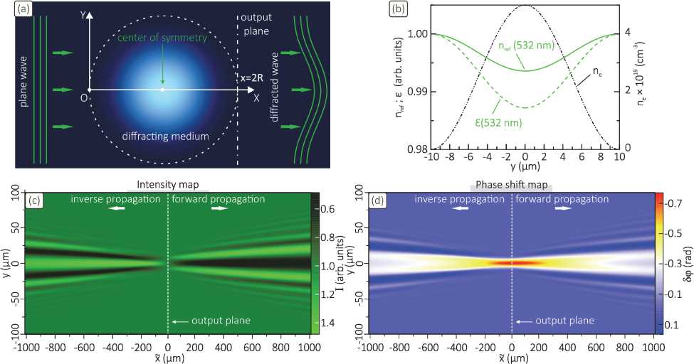
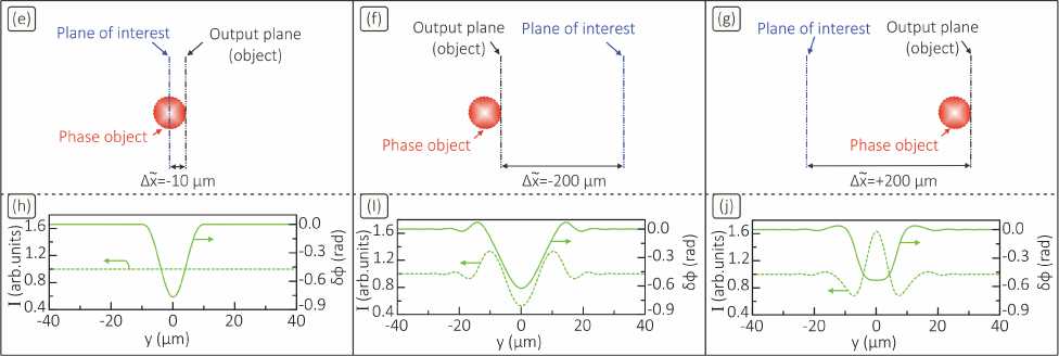
Fig. 1. (a) Schematic illustration of plane wave diffraction by a phase object. (b) Electron density n e , dielectric permittivity ε , and refractive index n ref of a plasma cylinder at 532 nm considered as a diffracting medium. (c) and (d) Simulated 2D maps describing the intensity and phase shift of the diffracted wave for its forward and inverse directions of propagation. (e)–(g) Considered relative positions of the object output plane and plane of interest. (h)–(j) Intensity and phase shift distributions obtained in the considered planes of interest
Mathematically, wave diffraction by the object can be described by solving the following equations [11]
Ψ1(x,fρ)=-k xΛ(x′,fρ)e-iλπ(x-x′)fρ2dx′,(1)
2 i 0
л( x, f> )= Г е(x, p) e-2П ipf’ d 2 P,(2)
-∞
Ψ1(x,fρ)=+∞Φ1(x,ρ)e-2πiρfρd2ρ,(3)
-∞
Φ1(x,ρ)=ikx+iδφ1(x,ρ)+ln(I1(x,ρ)/I0),(4)
where f y and f z are the spatial frequencies related to the coordinates y and z, and f ρ appears as the two- dimensional variable introduced for f y and f z. For convenience let us introduce auxiliary function χ1=ln(I1(x,ρ)/I0) understood as a wave level. Dielectric permittivity ε(x, ρ)= 1 + ε̃(x, ρ) of the object is considered in terms of fluctuations relative to the environment. The part of the object dielectric permittivity ε̃(x, ρ) can depend on the radiation wavelength and be complex. So, hereinafter, function ε̃(x, ρ) is understood as the disperse part of ε(x, ρ), but we exclude any other nonlinear effects (see, e.g., in [27]) during the wave passage through the object. From equation (1) phase shift and intensity of the diffracted wave are found as 5ф1 = Im (7-1(?i)) and 11 = Io* exp [2x Re (^(^i)], where symbol ^ 1 means the inverse Fourier transform. The criteria for the applicability of equations (1)–(4) are the following. First, characteristic scale ls ~s /| Vs | (here we have V = hxd / 5x + hyd / 5y + hzd / 5z) of the changes in the dielectric permittivity of the object is assumed to significantly exceed wavelength X of the probing radiation. Second, dispersion as of function s is assumed to satisfy condition
-
< | V^ | 2 > = 1/ v f | V1Ф 1|2 dv < k 2 c - V s
(function Ф1 is given by equation (4), and V± = d / 5y + d / 5z ). Here we have a = \'2>, = ^<[s -
(symbol <…> means averaging), and
-
=1/ V J V s dV ,
which is the mean value introduced for function s given in the volume V . In other words, smooth changes in the characteristics of the medium are assumed on scales of the order of the wavelength of the probing radiation. Parameter x is the distance at which the diffracted wave is considered behind the object. For this distance inequality X ( x - x ' ) / 1 s 2 < ( l s / X )2 is assumed to be satisfied allowing for a parabolic form of the Helmholtz wave equation [28]. Equation (1) takes into account the diffraction spreading of the wave during the propagation through the object and behind its output plane and also allows one to describe the propagation of the wave behind the object at distances satisfying the condition of the applicability of the first Rytov approximation.
Equation (1), while being obtained by solving the Helmholtz wave equation in the first Rytov approximation, points to a number of fundamental patterns of the diffracted wave behavior. Assuming the axial symmetry of the phase object, let us consider independently the cases of the object without and with radiation absorption. In the first case the disperse part of the object dielectric permittivity is real together with its spectrum, and equation (1) can be written as follows T i ( x , f p ) = T ( x , f p ) + iH ( x , f p ), where
H ( x , f , ) = 2 J 0 x cos ( Xn ( x - x ' ) f ,2 ) Л ( x ' , f , ) dx ' , (5)
kx
T ( x , f , ) = 2 J 0 sin ( Xn ( x - x ) f ,2 ) Л ( x , f , ) dx. (6)
Functions H = ^ ( оф 1 ) and T = 7 ( x 1 ) denote the twodimensional Fourier spectra of the wave phase shift and level distributions, which are defined behind the object in a certain YZ plane with the coordinate of x . Let us move the origin of the coordinate system in Fig. 1(a) to the object center and introduce parameter x̃ = x – R and new integration variable x" = x ' - R . In the new coordinate system the integrands in equations (5) and (6) can be expressed as
cos( Xn ( x - x '' ) f p 2) =
= cos(Xn xf,2) cos(Xnx "f,2) + sin(Xn xf,2) sin(Xn x "f22) and sin(Xn( x - x '') f,2) =
= sin( Xn xf ,2 ) cos( Xn x ' 'f ,2 ) - cos( Xn xf ,2 ) sin( Xn x ' 'f ,2 )
and the integration is performed from – R to R , since function Л ( x ' , f , ) outside the object region equals to zero. Let us take into account the fact that function Л ( x '' , f , ) is even with respect to the point x = 0, whereas function sin( Xn f ,2 x '' ) is odd. Consequently, the integrals (5) and (6) can be simplified to the following form
H ( x , f , ) =
= k cos ( Xn xf ,2 ) J 0 cos ( Xn x ' 'f ,2 ) Л ( x'' , f , ) dx' '
T ( x , f , ) =
= k sin ( Xn xf ,2 ) J 0 cos ( Xn x ' f , 2 ) Л ( x'' , f , ) dx' ' .
For convenience, the integral transformation in equations (7) and (8) can be denoted as function
@ ( f , ) = J 0 cos ( Xn x ' f ,2 ) Л ( x '' , f , ) dx ' ' .
2. Equation analysis when there is no absorption
Let us analyze obtained equations (7) and (8). These equations allow one to describe the wave propagation both inside the object and behind its output plane in free space, with the diffraction spreading of the wave in the periphery taken into account. Equation (1) constitutes the solution of the scalar Helmholtz equation, which was looked for taking into account the boundary condition T 1 ( x = 0, f , )=0 [28]. This condition corresponds to the start of the wave propagation through the object. Let us consider the wave, when it has passed through the entire object and further propagates in free space. The wave propagation in free space in equations (7) and (8) is characterized by the trigonometric factors outside the integrals. When we operate with the data measured in an experiment, the initial conditions in the form of the phase shift and intensity spectra are given in a certain plane with the coordinate of x̃ . The exact distance from this plane to the object output plane can be unknown. Moreover, even the exact position the object can be unknown, but the main thing is that the level and phase shift spectra of the diffracted wave are defined in the plane behind the object.
Let us now consider the plane with the defined level and phase shift spectra characterizing the brightness and phase patterns of the object and vary the values of x̃ in equations (7) and (8) assuming that the variable takes values x̃ < R. In other words, we consider the further changes in the shape of the level and phase shift spectra of the wave in free space assuming no object on the wave path. How should the wave propagation be understood in this case? If we were in the object output plane with the coordinate of x̃ = R, then the transition to values x̃ <0 could be interpreted as an artificial inversion of the propagation direction of the diffracted wave from this plane. In the absence of the object, the diffracted wave from the object output plane passes through the former region of the object including its former center with the coordinate of x̃ =0 and then propagates somehow in free space (x̃ < – R). Actually, such a consideration is applicable to any plane behind the object output plane.
Following this reasoning, one can find that the following relations are fulfilled
H(-x,fρ)=H(x,fρ),(9)
T(-x,fρ)=-T(x,fρ),(10)
R
H(0,fρ)=k∫0 cos(λπx′′fρ2)Λ(x′′,fρ)dx′′,(11)
T(0,fρ)=0.(12)
From a theoretical point of view, this means that within the framework of the first Rytov approximation the shape of the phase shift spectrum coincides on both sides of the object’s symmetry plane, whereas in the symmetry plane itself the phase shift spectrum has a characteristic inflection point along the longitudinal coordinate and completely coincides with the spectral transform of function ε ( x ′′ , ρ ). In other words, the symmetry plane appears as the surface of localization of the object phase pattern, when the object is exposed to a plane wave. In the symmetry plane the level spectrum equals to zero, i.e., the intensity distribution is indistinguishable from the incident plane wave intensity, and the object is invisible. However, the contrast of the object brightness pattern increases on both sides of the symmetry plane, as we move away from it. Moreover, when passing through the symmetry plane of the object (its center), there is an inversion of the contrast along the longitudinal coordinate. These regularities are known in photographic optics in the presence of the defocusing effect, but they have not been explicitly shown as a fundamental consequence of the wave diffraction equation (1) obtained in the first Rytov approximation.
Note that expressions (7) and (8) have the same kernel of the integral transformation and establish the unified relation, which relates the phase shift spectrum to the level spectrum for each longitudinal coordinate x̃ of the diffracted wave propagation
T ( x , f ρ )/ H ( x , f ρ )=tan ( λπ xf ρ 2 ) . (13)
The relation is satisfied for all x̃, for which the employment of the first Rytov approximation is permissible, see the details in the study [28]. The limitations imposed on equation (13) are individual for each specific phase object and can only be clarified in detail in terms of numerical simulations. However, if the relation governed by equation (13) is satisfied, then opportunities open up for simplifying laser diagnostics of the investigated phase object. For example, it is sufficient to register only the intensity or phase shift distribution in a certain plane behind the object, since the spectrum of the wave level related to the intensity changes is expressed through the phase shift spectrum in accordance with (13). This eliminates in experiments the need to create complicated laser interferometry systems for registering the object phase patterns, which are crucial for solving the inverse diffraction problems and reconstructing the object optical characteristics. Relation (13) also explains the principle by which the well-known Gerchberg-Saxton method [30, 31, 32] is implemented, when lensless diffraction methods are employed to reconstruct the phase shift from the intensity distributions of the diffracted wave detected in the far-field region. At the same time, relation (13) points to the fundamental limitations of its applicability, when there is radiation absorption in the object.
3. Numerical simulation and verification
The discussed regularities in the diffracted wave characteristics are of a fundamental nature, but it is important to evaluate them on a particular example. Let us assume a phase object in Fig. 1a to be represented in the form of a plasma cylinder (filament, which appears as a single element of the electric spark microstructure [29]) 20 µm in diameter (2R), which is exposed to a plane wave at 532 nm. The filament properties, which are plasma electron density ne, dielectric permittivity ε, and refractive index nref, are given in Fig. 1b. The electron density profile is taken to be ne(y) = A(1 + cos(πy / R)) /2, where A = 5×1019 cm– 3 is the dimension factor, and has axial symmetry in x = R. With the considered properties of the plasma the latter appears as a purely phase object, i.e. there is no the radiation absorption. The filament’s dielectric permittivity is determined as ε=1-ω2pe /ω2, where ωpe =(4πe2ne /me)1/2 (e and me are the electron charge and mass) and ω are the plasma and radiation frequencies, as well as we have ε=-ω2pe /ω2. By simulating equations (1)–(4) for different values of x̃, we obtained in Figs. 1c and 1d the 2D maps describing the intensity and phase shift of the diffracted wave traveling in the forward and inverse directions of its propagation. For a number of the planes of interest in Figs. 1e–g we plotted the distributions of the wave intensity and phase shift in Figs. 1h–j. It is seen that wave diffraction by the filament is accompanied by the intensity and phase shift fluctuations on micron-sized scales falling within a diffraction cone, the apex of which coincides with the object region. When the wave travels in the forward direction of propagation, the central part of the diffraction pattern is characterized by a decrease in the wave intensity, since the plasma acts like a ’negative lens’. Opposite to this, for the case of the inverse direction of propagation, the wave diffraction pattern in its center is characterized by an increase in the wave the intensity, i.e. for such a consideration of the wave propagation the plasma acts like a ’positive lens’. So, when proceeding from the right to the left sides of the object output plane, the inversion of the contrast of the object brightness pattern occurs. In each case of the diffracted wave propagation the phase shift has a similar behaviour, and its maximum value is reached in the vicinity of the object center. Herein one can also distinguish a sharp drop in the contrast of the object brightness pattern, i.e. the object becomes invisible, and the object’s phase pattern turns out to be localized directly in the object center, i.e., is registered as correctly as possible. The mentioned facts are in good agreement with the results predicted by relations (9– 12).
Finally, let us note an important point regarding the stability of the numerical solution of the direct diffraction problem described by equations (9– 12). We investigated the problem on the example of modeling diffraction of a laser beam passing through plasma microstructures, previously considered in [26]. It was found that small artifacts (e.g., noise) artificially introduced into the characteristics of the diffracted wave significantly affects the picture of the wave front behind the object. In this regard, the above-described regularities in the wave diffracted by an ideal axisymmetric phase object are limited in their application, but can still serve as useful tools in numerical and experimental studies. Notably, a number of fundamental patterns of the diffracted wave behavior are preserved even in the case of a complex-structured phase object. These are, e.g., the drop in the object brightness pattern and the local inversion of the intensity fluctuations, when passing through the resultant center of the object. This fact was observed in the experiments carried out in [26].
4. Equation analysis in the case of radiation absorption
If radiation absorption occurs in the object, the dispersion part of the object dielectric permittivity and its spectrum take the form of ε ̃( x ̃, ρ ) = ε ̃ 1 ( x ̃, ρ )+ i ε ̃ 2 ( x ̃, ρ ) and Λ ( x ′′ , f ρ ) = Λ 1 ( x ′′ , f ρ )+ i Λ 2 ( x ′′ , f ρ ), respectively. By substituting functions Λ 1 ( x ′′ , f ρ ) and Λ 2 ( x ′′ , f ρ ) into equation (1), we obtain the corresponding equations describing the phase shift and intensity spectra
H ( x , f ρ )=
= k cos ( in xf 2 ) @ 1 ( f ,) + k sin ( in xf 2 ) ® 2 ( f ,), t ( X , f , ) =
= k sin ( in xf2 ) ® i ( f p ) - k cos ( in xf 2 ) ® 2 ( f , ),
where functions
R
Θ1(f )=∫0 cos( λπx′′f 2)Λ1(x′′,f )dx′′ and
R
Θ2(f )=∫0 cos( λπx′′f 2)Λ2(x′′,f )dx′′ are introduced.
In the presence of radiation absorption the diffraction pattern turns out to be more complex. It becomes possible to fully reconstruct complex dielectric permittivity function ε ( x , ) = ε 1 ( x , )+ i ε 2 ( x , ) only from the results of simultaneous registration of the intensity and phase shift of the diffracted wave. The diffraction pattern described by equations (14) and (15) is asymmetric with respect to the symmetry plane with the coordinate of x =0. There is no inversion of the contrast of the object brightness pattern, and the distributions of the phase shift and intensity are not similar to the distributions on both sides of the object’s plane of symmetry. In the plane of symmetry itself the following relations are fulfilled
H (0, f ) = k Θ 1 (0, f ), (16)
T (0, f )= - k Θ 2 (0, f ). (17)
It can be seen that the phase shift spectrum describes real component ε 1 ( x , ) of the object dielectric permitivity, and the inverted intensity spectrum describes complex part ε 2 ( x , ). At the same time it is impossible to construct any relatively simple analytical relation, which can relate the spectra of the phase shift and intensity in free space.
Modeling of equations (7), (8) and (14), (15) allows one to evaluate radiation absorption in the object by analyzing simultaneously the behavior of the twodimensional spectra of the intensity and phase shift of the diffracted wave in the object’s plane of symmetry and around its vicinity. When analyzing the experimental data, one can first consider a model without absorption and check the validity of relations (9 – 12). If they are unsatisfied, then further consider a model with absorption and analyze the validity of relations (16) and (17). To a large extent, this approach saves time and makes the data processing task less resource-intensive. It should be noted that the fundamental regularities in the behavior of the diffracted wave, predicted by relations (9 – 12) and (16) and (17), allow one to implement a method for localizing a phase object in space, even when a single angle of laser probing is employed. Such a method was previously proposed in [26, 33], when localizing plasma microstructures in space using spectral convolution describing the propagation of the angular spectrum of the wave in free space [34]. The efficiency of the method, however, went far beyond the case of only axisymmetric phase objects and allowed the creation of the method to localize even complex-structured phase objects in space.
Equation (7) establishes an unambiguous connection between phase shift spectrum H(x̃, f ) and spectral representation Λ(x̃, f ) of dispersion part ε(x̃, f ) of the object dielectric permittivity. Equation (7) can be analytically inverted within the framework of solving the inverse problem, i.e. function ε(x̃, f ) can be expressed in terms of H(x̃, f ρ) taking into account the specific plane, in which the phase shift spectrum is determined. With such an approach function ε(x̃, f ρ) can be retrieved taking into account the diffraction effects, which accompany the propagation of the probing wave through the object and are enhanced in free space behind the object output plane [26]. Here the accuracy of ε(x̃, f ρ) reconstruction is much higher than that achieved when solving the inverse diffraction problem in the geometrical optics approximation (associated with solving of the inverted Abel integral equation) [35]. Similarly, it is possible to construct the solution of the inverse diffraction problem for wave level spectrum T(x̃, f ρ), i.e. by using the data on the wave intensity changes. Owing to this, one can significantly simplify the implementation of laser diagnosing techniques for studying phase objects in experiments, since there is no need to organize a complicated interferometry system and obtain the object phase patterns. The solution of the inverse diffraction problem can also be derived for the case when radiation absorption occurs in the phase object. In the case at hand, the solution is obtained separately for the real and imaginary parts of function ε(x̃, f ρ) based on equations (16) and (17).
Conclusion
Thus, the findings of this study can serve as a promising basis for the development of new methods for laser diagnostics of phase objects and processing their images. This includes the creation of highly-efficient approaches to imaging phase objects within nano- and microscales on subnanosecond and nanosecond timescales, while preserving a high spatial accuracy of the object localization and reconstruction of its optical characteristics. The findings are of a general nature and can be useful to elaborate new methods of imaging of various objects in the terahertz, radio and X-ray wavelength ranges.
Acknowledgements
The study was supported by the Russian Science Foundation (Grant No. 19-79-30086).
