The method of hidden terminal transmission of network attack signatures

Author: Igor Ruban, Nataliia Lukova-Chuiko, Vadym Mukhin, Yaroslav Kornaga, Igor Grishko, Anton Smirnov
Journal: International Journal of Computer Network and Information Security @ijcnis
Article in issue: 4 vol.10, 2018.
Free access
This article is proposes a new approach to the transmission of signatures of network attacks onto a remote Internet resource. The problem is that the known protocols that are used for transfer data and control actions from an administrative resource to a network agents are poorly protected. Even in case of use of cryptographic mechanisms for organization of secure connections, it is possible to form behavioral patterns of interactions such as "administrative resource - network agents." Such templates allow to predict the actions taken in accordance with the security policy in order to maintain the required level of functionality of a remote Internet resource. Thus, it is necessary to develop a new protocol for the transfer of designated information, based on information technology, which level out the existence of opportunities for the formation of behavioral patterns of network interactions. As such technology, it is proposed to use a set of means of network interaction and some methods of hidden (steganographic) data transmission in information and telecommunication networks.
Steganography, network steganography, hidden data transfer, covert channels
Short address: https://sciup.org/15015589
IDR: 15015589 | DOI: 10.5815/ijcnis.2018.04.01
Text of the scientific article The method of hidden terminal transmission of network attack signatures
First of all, functional stability (FS) of an information system (IS) provides regulated services during the specified time interval. This interval is determined by the customer and by the ability of the system to serve customers during the time, which it is necessary to switch to backup servers, to implement methods of detection and location of the intruder, etc. For detection of unauthorized access information or unauthorized information system management through the global network, intrusion detection system (IDS) is used. Functional stability of IDS should have the ability to receive, handle signature information at the initial stage of the network attack, and create various schemes for the formation of control impacts. This will enable to catch in time the attack and develop the necessary administrative impacts on the information security system (ISS). In this case, the collection of signature information should be hidden. This is due to the fact that the attacker will monitor the network activity of the intrusion detection systems in order to reduce the risk of being detected.
Remote control of IDS is provided through the operation of the TCP / IP protocol stack (Transport Control Protocol / Internet Protocol). The essence of management is the continuous information security system adaptation to appropriate external attacks, based on the signature information of agents that are located on network devices within the responsibility of the intrusion detection system. To collect and transfer such data, it is necessary to select an existing one or to develop a new protocol for the transmission of signature information. Nowadays there are many protocols that can provide the required services, but the fact of their flexible existing in the network can allow (to allow) the intruder to analyze and disturb the FS of the information system. At the same time, the security of the data, being transmitted, is ensured by the use of cryptographic transformations, but to conceal the fact of the transfer, such methods are not applied.
For the masking of transfer important information in the information and telecommunication networks (ITN), the methods of network steganography, which are based on the use of structural properties of OSI protocols (Open System Interconnection - network interconnection of open systems) are widely used in recent times. This allows you to conceal the transfer of background data, without any significant reduction in the data rate in the base (open) channel. When it is correctly chosen the properties (group of properties) of the protocol (protocols) of the OSI model, the methods of network steganography do not allow stegano-analytic to detect the presence of hidden data terminal transmission.
-
II. Main Part
The analysis of the methods of network steganography channels building
Due to network steganography, the process of detecting hidden data terminal transmission is based on the analysis of the protocol features of the protocols used by the OSI model for meeting the requirements of the standards. In the article under this analysis is meant to detect (attack) by a known mathematical model.
The use of OSI model channel and network layer protocols is carried as a technological basis for organizing a hidden data terminal transmission channel. During this, the concealment is carried out by placing data, whose transmission is to be hidden in the header fields of the corresponding protocols. This fact will cause the data transfer in the ITN as a flexible existing. Due to the fact that even with the use of IP-encryption technologies, only the useful loading of network layer protocols is cryptographically protected and it would be appropriate to use the transport layer protocols of the OSI model. At this level, the most common is the TCP protocol that is standardized and used by the opposing sides.
Network Steganography is the direction of computer steganography, which work at identify the properties (features) of protocols OSI model that are suitable for the organization of hidden data terminal transmission channels.
WLAN (Wireless Local Area Networks) steganography is based on the methods, used to transmit steganographs in the wireless networks. A practical example of WLAN steganography is the HICCUPS (Hidden Communication System for Corrupted Networks) [2]. On the base of these methods are the wireless networks disadvantages, which can cause distortion of the power features of signals on the air. As a result, "incorrect" packages (checksum which do not match the declared ones) may appear. To implement such methods, it is necessary to have actual statistics of network activity in the environment of the functioning of the steganographic system in order not to cause abnormal network activity.
LACK (Lost Audio Packets Steganography) steganography –is the hiding messages while talking using IP telephony. For example is the use of packets that are delayed or deliberately damaged and ignored by the receiver (application program), but not the steganographic application [9, 10].
Due to the fact that the most widespread on the Internet is the stack of TCP / IP protocols, then it would be appropriate to organize the Steganographic Channels (SCs) on its base.
Under the definition of network steganography at the network level of the OSI model (referred to as IP -steganography) is understood as a group of methods of network steganography, in which the basis of the stegocontainer are unused (reserved) places in the headings and fields of the IP datagram data [9].
The example of the use of IP header fields is a method based on the modification of the fields "identification" and "fragment offset" [7, 8] with the flag "DF" (do not fragment). If the DF flag is set, the IP module will not fragment the datagram. Instead this, the datagram is rejected and ICMP [11] generates an error message -"required fragmentation, but the fragmentation allowance flag is set", which refers to the sender of the package. If the IP datagram has been fragmented, then each fragment becomes a separate packet with its own IP header. Such packets are routed independently, and as a result, fragments of the datagram can come to the destination with a disturbance of their order. However, the IP headers of the fragments contain all the necessary information for their correct assembly at the destination point.
Fragmentation in the IP is performed regardless of the transport layer of the OSI model. Nevertheless fragmentation can lead to undesirable effects that affect the levels above the IP. Because of the loss of a single fragment, you need to re-transmit the entire datagram, and since the IP protocol itself does not have timeouts and retransmissions, these functions are assigned to protocols of the higher levels of the OSI model.
The TCP protocol make repeated transmission by timeout, and UDP does not. If it is provided that a part of the TCP segment has been lost, then the transmission will be repeated by the timeout. Repeated transmission of a single fragment of an IP datagram is not possible. Exactly, if fragmentation was not made by the datagram source, but by one of the intermediate routers, then the source can not know exactly how the fragmentation was performed. That’s why it is desirable to use methods to prevent fragmentation. Fragmentation of packets in the IP is a regular situation, so the use of the previously marked fields of IP packet headers as a stegcontainer is a perfectly appropriate method for organizing hidden data terminal transmission channels .In case of the right choice of package size, you can satisfy the following condition:
L < PMTU , (1)
where L is the package length;
MTU - maximum transmission unit;
PMTU – MTU from source to final receiver.
PMTU = min MTU,, (2)
where min MTU – minimal MTU among variable routes which will be used.
If the condition (1) is satisfied, there is no need for fragmentation of packets on the route interfaces. This means that the fields "identification", "flags", "fragment offset" will not be processed by intermediate routers. In this case, when using these fields as a stegocontainer, the information embedded in it will be transmitted unchanged. The capacity of such a stegocontainer can be up to 32 bits.
The use of this method for the transmission of signature information is inappropriate, due to the offend of the standard IP protocol requirements, and the concealed data are arranged explicitly in the headers of IP-packets.
It should be noted that other fields of IP datagram headings may exist, which can be used to organize hidden data terminal transmission channels in information and telecommunication networks. These fields include IPv4 options, which can reach 40 bytes shown on (Figure 1).
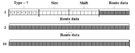
Fig.1. The view of Option ‘Route record’
To the options that are suitable for the transmission of signature information, Itit is necessary to include the following: "record the route", "time stamp," "routing from the source." The common feature of these options is to allocate enough (up to 40 octets) space in the IP packet header to implement them. The option field is optional, but their support should be implemented in all IP modules (hosts and gateways).
The theoretical basis of the "option method" [12] is described by the example of the "route record" and "time stamp" option. When it is used the intermediate node device (option "Record Route" or "Record Route (RR)) as a stegocontainer, it is possible to achieve the size of the container is up to 37 bytes. The RR option is intended to write in the datagram header of the IP addresses of the source interfaces of the routers that will scan the given datagram. It is possible to record up to 9 IP addresses by using this option. That’s why that IP- the datagram is allocated to 40 bytes for options describe, three of which - the title option RR.
The option starts with field ‘option type’, than it goes field ‘length’ that takes into account the full size of the option (type, size, shift, route data). The third octet contains a pointer for the octet from which the next area of the route begins. Shift is deducted from the start of the option, so the value of the pointer can not be less than 4. During sending a datagram, the host must provide sufficient space (option size) to record addresses on the path to the recipient. In the source datagram, the fields of the addresses must contain zero values. When the IP module routes a datagram, it checks for itinerary records.
In the presence of such records, the module places its address to it, known in the environment to which the datagram is forwarded, starting from the offset specified by the pointer, and increasing the value of the pointer by 4.
If the path field is already filled (the pointer value exceeds the size of the option), the datagram is forwarded without further route record. So, if the hidden information is written in the fields, intended to write the IP addresses of the source interfaces, on the transfer side and the following condition is fulfilled for the fields "offset" and "size", then this datagram will be delivered unchanged:
Lp < L1 ,
where L - the octet of route data, which will be used for p the next parameter, existed in the reference option;
L - the size of the option (in octets), taking into account the fields of the type and size of the option, as well as the pointer octet and the actual options.
For implementation of this method, it is necessary to have special software on the side of the sender and the addressee of the data, which is hidden during transmission. When the current router will not be able to write the required information in the option is the standard situation for the IP protocol [9]. If the condition (3) is satisfied, this approach can be applied to the remaining IP-SR options (source route), TS (time stamp). It is given 37 bytes for recording of the required data for the "source routing" and "route record" options and 36 bytes per IP datagram for the "time stamp" option. This value determines the capacity of such a stegocontainer. During the option "time stamp" (Figure 2), the smaller capacity of the stegocontainer is due to the fact that in the fourth octet the option fields store the information necessary to execute the destination option.
The "surplus" field shows the number of routers that failed to perform the required operation. The "flag" field can have the following values:
-
- 0 - intermediate routers must record only time
stamps that are stored in a sequence of 32-bit words;
-
- 1 - the IP address of the module registering the label
is placed before each tag;
-
- 3 - the address fields are specified in advance and
the IP module puts the timestamp only if the address of this module is listed next in the list of address options.
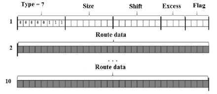
Fig.2. The view of Option” Time Stamp”
The use of this method without the use of cryptographic transformations is inappropriate because of the concealed data that is located explicitly in the field of headers of IP-packets in the explicit form.
The network steganography on the transport layer of the OSI model (as TCP - steganography) is a group of methods of network steganography, in which the basis of the stegocontainer is the technological features of the transport layer protocols of the OSI model.
One of the methods of TCP - steganography is a method based on the management of the length of the payload field of the TCP protocol - the method of "Data Length" (DL) [7].
The essence of the DL method is that the secret text is represented as a sequence of bits, which are transmitted as parts to the receiver. This is due to the fact that the capacity of the stegocontainer is limited. So if you need to transmit a large amount of information, it must be divided into parts. The stegocontainer is the length of the data field of each information TCP segment, represented in the binary form of the calculation. It is said in [10] that if the parties do not discuss the maximum size of the segments - MSS (Maximum Segment Size - maximum segment size) in the case of "triple handshakes" at the beginning of the TCP session, then its value is set to 536 bytes by default. In the work [7] the author proposes to convey hidden information in the form of text, where each symbol corresponds to a binary sequence with an acceptable table encoding. For this method, this may be the Windows-1251 encoding (table CP1251). This encoding is 8-bit. Due to this the length of the TCP segment data field will be calculated as follows:
DL = MSS - L4 = 536 - 20 = 516
where L - the length of TCP- segment header without options.
In this case, the quantity of digits of the binary value of the length of the open text corresponds:
L OT = Lm 1
,
where L^ = log2( DL ) ® 9,07, it takes around 10 bits.
The TCP-dump of the data transfer process based on the DL method is shown on Fig. 3. The method requires the receipt of confirmation of the delivery of each segment before sending the next. This is done by using the PUSH flag (push data flag).
TCP: 50240 > §£ft£QfSjg [SYN] SeQ=0 Win=32792 Len=O MSS=16369 TSV=528243 TSER=O WS=6 TCP: ЯЗШгпЙЕ > 50240 [SYN, ACK] Skj=0 ACK=1 Win=32758 Len=O MSS=16369 TSV=528243 TSER=528243
TCP: 50240 > SCfcCOnf i£ [ACK] §gg=l A£k=l Win=32832 Len=O TSV=528243 TSER=528243
TCP: ЯЗШгпЙЕ > 50240 [ACK] ,$eg=l ACK=117 Win=32768 Len=0 TSV=529497 TSER=529497
TCP: sohconte > 50240 [ACK] SfiQ=l ACK=218 Win=32768 Len=O TSV=529523 TSER=529523
TCP: SCRSOTrfjg > 50240 [ACK] Seg=l ACK=333 Win=32768 Len=0 T5V=529529 TSER=529529
Fig.3. The TCP-dump of the Data Transfer Process based on the DL Method
The author uses cryptographic transformations to achieve greater stability to the selection of hidden information. Cryptographic transformations are the use of encryption of concealed text, dispersion of concealed text in binary values of the length of data fields of TCP segments with the use of a secret mask, which represents a binary sequence, the unit values of which correspond to information and zero to camouflaging segments. This method has the ability to transmit any data that can be represented by 8 digits in a binary system. It may be: text, images, audio, video, and more.
In [1] is proposed a method that allows the transmission of concealed data within the TCP packets, which are sent as to correct unsuccessfully transmitted data. This algorithm is called RSTEG (Retransmission Steganography - Retransmission Steganography).
The described method of hidden data terminal transmission can only be used under certain conditions that may arise in the basic, virtual data transmission channel.
The principle of functioning of RSTEG is shown on Fig. 4
The addressee accepts the original package and sends a message about the successful reception. Instead of passing the next package, the sender ignores the message of a successful receipt and sends the packet with hidden content, but this package has the same identifier as the previous one. Network traffic analysis systems do not check the re-package.
For all network protection systems, the new package with secret content does not differ from the original package, which did not contain anything suspicious. When the retransmitted packet reaches the addressee, hidden information is removed from it.
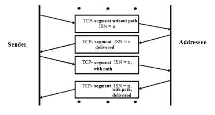
Fig.4. The Principle pf RSTEG
This method is characterized by low data transfer speed in the steganographic channel, but in case of active application of the method, the number of retransmissions significantly increases compared with the average indicator. The normal situation for the TCP protocol is the loss of 0.1% of the transmitted segments. If the losses are 1-2%, it performs its functions incorrectly. To implement this method it is necessary to have the statistical characteristics of the medium, used for the transmission of concealed data.
Similar to RSTEG, there is a method based on the modification of the network packets of the VoIP traffic traffic - LACK.
LACK is a method of steganography for IP-telephony
[5], which modifies packets with voice stream (Figure 5). He uses the fact that excessively delayed packets are considered to be false and rejected by the receiver in typical multimedia communications protocols such as RTP [13]. This method is hybrid, because it is based on the use of features of interoperability of transport protocols (UDP) [14] and application (RTP) levels. This is due to the expediency of using UDP as a transport protocol and the ability to retransmit some of the corrupted packages. The control of the retransmission is based on the interaction of the protocols RTCP [15] and RTP.
The sender selects one of the packets of the voice stream and replaces the bits of the payload with the bits of the concealed message - a steganogram that is embedded in the package № 4 (Figure 5). Then the selected package is deliberately delayed. Each time an excessively delayed packet reaches a recipient who is not familiar with the steganographic procedure, it is discarded. However, if the recipient knows about a hidden communication channel, instead of removing the received RTP packets, it removes the hidden data. The bandwidth of the channel, organized on the basis of this method, allows to transmit up to 1.3 MB of information per session for duration of about 9 minutes (average duration of IP telephony calls in both directions).
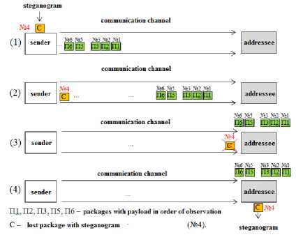
Fig.5. The Principle of LACK
Confirmation of delivery of steganographs is not provided at the network level (IP protocol) or at the application level (RTCP protocol), and hidden transfer is possible only in case of use of multimedia VoIP applications.
Another representative of TCP - steganography is the method for managing the generation of initial sequence numbers (ISNs) of the TCP protocol - the ISN method (the initial sequence number is the initial sequence number) [16]. The basis for its operation is the mechanism of generating the ISN of each TCP connection and the correlation of the bytes of data transmission and bytes of the secret message.
According to [10], in case of a TCP connection, the generation of an initial sequence number is based on the current (possibly fictitious) 32-bit time value in which the younger bit increases every 4 microseconds. But the ISN value is calculated in different operating systems in different ways. In the general case, this value is a kind of time stamp and corresponds to the value of a function whose argument is the current value of computer time (the ISN is a function of F (t)).
Thus, the value of ISN is random for a third-party observer. In the first implementations of such functions it became possible to determine the legality (to approximate the function), and to select the value of the ISN in order to intercept the TCP connection.
In the TCP header, the ISN value is written in a 32-bit field (Figure 6).
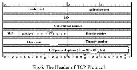
The data transmitted by the TCP fragment is represented as a sequence of bytes that have "through" numbering. The number of the first transmitted data byte corresponds to (ISN + 1).
A fragment of the Ethernet-frame, presented in the 16-axis system, is shown on the fig. 7. The interval from zero to 54 bytes includes headings for the channel, network and transport levels of the OSI model. The transport layer protocol header (in this case, TCP) is highlighted by gray and starts with 55th byte if the first bit of the Ethernet frame is taken at the beginning of the countdown.
00 30 48 14 72 с9 14 da 05 de 2d e4 40 00 80 06 02 64 d3 4d 01 bd 42 6a 3e be e3 df 00 00 00 00 00 00 00 18 07 c8 00 00 00 00 06 08 ff fe 00 10 10 00 00 00 00 ff IF ff e9 61 6d 71 08 00 4500
40 94 cO aS 02 ef cOa8
a7 16 96 6e 9d ef 5010
41 04 ff 53 4d 42 2f00
11 9e 55 78 e9 34 008d
80 la Oe ff 00 de deOd ff 00 00 00 00 00 00c4
e8 20 ее f6 e5 ed ea eO
ее e8 П ea 20
20 eO ed ее ее eO ed e8
Fig.7. The Fragment of Ethernet-frame
Data application (file * .txt) are transmitted in the CP1251 encoding. In the beginning, the text (highlighted in black on Figure 7) corresponds to 123 bytes from the beginning of the frame. It is preceded by 68 bytes of service data for the application.
For hidden transmission, for example the word "volley", in case of use as a stegocontainer the "sequence number" and "data" of the TCP-fragment, it is necessary:
-
- number the bytes of the "data field" starting from the zero value;
-
- to match each letter of the word "volley" with the number of bytes in the data field;
-
- in accordance with the sequence of the letters in the secret word, fill in the corresponding values 32-bit
field "sequence number";
-
- send the generated fragment to the recipient;
-
- on the reception side, pull the hips in reverse order.
On fig. 7, parts of text data are highlighted in the text by black color, in accordance with the order numbers of bytes, and the letters of the concealed message "salvo" are selected: "з" - 8710 - 5716 - 0001 01002, "a" - 7710 -4D16 - 0101 01112, "л" - 9310 - 5D16 - 0101 11012, «п» - 6710 - 4316 - 0100 00112.
It is necessary to generate the required ISN number. In the TCP / IP protocol stack, filling in the headings and fields of data is done in the order "from senior to younger". The required starting sequence number looks like 000101000101011101011101010000112 = 4126982710.
It follows that upon the declaration of such an ISN, the first byte of transmitted TCP data will have the number (341269827 + 1) 10. The subsequent operation of the TCP protocol corresponds to the version implemented in the operating system.
Under the stegocontainer, it means upgraded to covert data transmission of the TCP connection as a whole.
The message refers to data secretly transmitted by the stegochannel.
Under the stego means a part of the message that is transmitted in one stegocontainer. Under the covering object is understood the text that is transmitted within the open channel of data transmission.
Under the informative meaning is the value that corresponds to the number of the character in the reference text used during the encoding and belongs to
0 ≤ n ≤ 127
the interval, where
where n - number in
the order of the location of symbols of the reference text, according to the message symbol.
Under non-informative meaning is the value used when encoding as a "marker", in the absence of the current character of the message in the next block of 128 characters of the reference text, or in addition to the next block required to calculate the required ISN number, up to four values.
During simultaneous use of several methods for the organization of a hidden virtual communication channel, it is possible to achieve a higher speed of hidden data terminal transmission.
-
III. Development of Requirements For Protocol of Signatures Transmission of Network Attacks
In relation to use of network steganography channels as a virtual medium for the operation of the protocol, important tasks such as organizing the protection of messages from channel damage (error-protection, integrity) and third-party intentional changes (offender actions) are solved by standardized network protocols, which structural features are the basis of the network steganography channel [17 – 19].
The addressing procedure for network steganography channels should be based on the data used in the network routing protocols. This is necessary to determine the status of the network objects ("connected" or "not connected"). Data about such states should be stored on all devices in the network as routing tables and route searches should be performed on the basis of known algorithms (Dijkstra's algorithm). So the protocol header will have enough 8 octets (may be smaller if necessary) to uniquely identify the address of all managers and agents (256 devices). To determine the address of the addressee of the message, it is necessary to provide a field of the same size in the protocol header. The message sender, based on the routing table, will determine the first device in the calculated route, and will send him a message. All intermediate devices must read the addressee's address and transmit the message without modification to the addressee based on their own routing table. If the address space is increased to more than 256 subscribers, it will be necessary to increase the number of octets allocated to the address of the sender and the addressee. The number of bits that need to be allocated to the address of the sender and addressee can be calculated as follows:
The structure of the TCP connection by the ISN method is shown on Fig. 8.
N = log 2 M ,
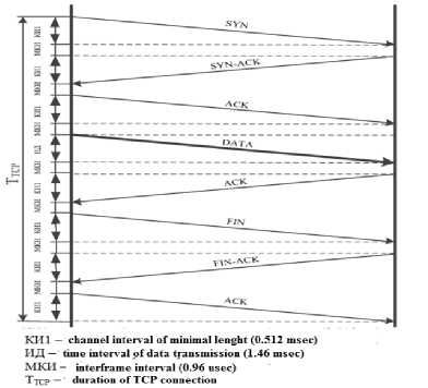
Fig.8. The Structure of the TCP Connection by the ISN Method
where M is the capacity of the address space;
N is the number of bits that are minimal and sufficient
to accommodate any value from the address space whose
value (
∆
) belongs to the interval 7.
∆∈[0;M-1]
Due to the conditions and in order to save space, the size of the fields in the protocol header to accommodate the sender and message recipient addresses must be dynamically varied, depending on the number of agents involved.
The payload field of the protocol should be divided into two parts: the control commands and the status field of the agent (manager), or create two types of messages indicating the type in the protocol header. The size of
these fields will be determined by the number of possible control commands and the number of system stability indicators. The size of the fields, assigned to determine the type of each individual variable (control team) and their values, are determined separately, based on the space of possible values. The general view of the structure of the protocol is shown on Fig. 9
Type of message Sender address Receiver address on ro commands

Control commands and agent's status field
Control commands and agent's status field
-
Fig.9. General View of Protocol Structure
The protocol should ensure the management and control of devices and applications in the communications network by exchange of control information between agents located on network devices and managers located at the control stations. The protocol will define the network as a set of network control stations and network elements (gateways and routers), which together provide administrative communications between network control stations and network agents. In this case, network agents should be located on a sufficient number of network elements to ensure the system's functional stability [20 - 21].
The use of the protocol extends to managed and control systems. A managed system includes a component called an agent that sends reports to the control system. In essence, agents transfer control information to management systems as variables (such as "channel load", "the number of SYN requests by TCP", "frequency of SYN requests over TCP", "changes in the configuration of the managed device," etc.).
A control system can obtain reliable information through protocol operations. The agent can independently send data without request by use the appropriate protocol operation. Control systems can also send configuration updates or control requests for direct management of the system. Configuration and management operations are only used, if network infrastructure changes are required. Monitoring operations are carried out on a regular basis.
Variables that are accessible through the protocol must be organized in the hierarchy. These hierarchies and other metadata (such as the type and description of the variable) will be described by the Guidance Information Bases (GIB).
So the protocol will have three types of messages: server-wide broadcast request, server-side query, agent request. Because the manager can perform both broadcast (for the general configuration of the network of agents) and individual (for the configuration of the specified agent) queries. The agent can transfer information about its condition only to the manager.
An important issue is the allocation of a sufficient space for posting addresses of the sender and recipient in the header of each message. In the case of the use of network steganography data transmission channels for the operation of the protocol for the transmission of network attacks, the number of functional nodes involved in the operation.
References The method of hidden terminal transmission of network attack signatures
- Mazurczyk W. Steganography of VoIP Streams / W. Mazurczyk, K. Szczypiorski. – Warsaw University of Technology, Faculty of Electronics and Information Technology, Institute of Telecommunications [Electr. resource]. – Accessed to: http://arxiv.org/pdf/0805.2938v1/.
- Szczypiorski К. HICCUPS: Hidden Communication System for Corrupted Networks / K. Szczypiorski – Warsaw University of Technology, Institute of Telecommunications [Electr. resource]. – Accessed to: http://krzysiek.tele.pw.edu.pl/pdf/acs2003-hiccups.pdf.
- Kundur D., Ahsan K., Practical Internet Steganography: Data Hiding in IP, Proc. Texas Wksp. Securit of Information Systems, Apr. 2003 [Electr. resource]. – Accessed to: http://arxiv.org/pdf/1207.0917.pdf.
- E. Cauich, R. Gómez Cárdenas, R. Watanabe. Data Hiding in Identification and Offset IP Fields. In Proceedings of 5th International School and Symposium of Advanced Distributed Systems (ISSADS), jan. 2005. – P. 118-125 [Electr. resource]. – Accessed to: http://webdia.cem.itesm.mx/ac/raulm/netsec/ prod_cientifica/2005/DataHidingIPHeader.pdf.
- Hiding data in the OSI network model. Theodore G. Handel, Maxwell T. Sandford II [Electr. resource]. – Accessed to: https://static-content.springer.com/lookinside/chp%3A10.1007%2F3-540-61996-8_29/000.png.
- Jankowski B., Mazurczyk W., Szczypiorski K., PadSteg: Introducing Inter-Protocol Steganography - In: Telecommunication Systems: Modelling, Analysis, Design and Management, Volume 58: 1-2 January/February 2015, ISSN: 1018-4864 (print version), ISSN: 1572-9451 (electronic version), Springer US, Journal no. 11235.
- Stanev S., Szczypiorski K., International Journal of Electronics and Telecommunications, Volume 62, Issue 3, Pages 315–318, ISSN (Online) 2300-1933, DOI: https://doi.org/10.1515/eletel-2016-0043.
- Murdoch S.J., Lewis S., Embedding Covert Channels into TCP/IP. Information Hiding (2005) 247-267.
- "Internet protocol – DARPA Internet Program Protocol Specification" RFC-791 USC/Information Sciences Institute, September 1981 [Electr. resource]. – Accessed to: http://www.rfc-base.org/txt/rfc-791.txt.
- "Internet protocol – DARPA Internet Program Protocol Specification" RFC-793 USC / Transmission control protocol, September 1981 [Electr. resource]. – Accessed to: https://tools.ietf.org/html/rfc793.
- "Internet protocol – DARPA Internet Program Protocol Specification". RFC-792. Internet Control Message Protocol - IETF Tools, September 1981. [Electr. resource]. – Accessed to: https://tools.ietf.org/html/rfc79.
- Ruban, I., Smirnov A., The TCP-connections processing model for steganographic data transfer in information telecommunication networks. Modern Information Technologies in the Sphere of Security and Defence 3(24), Pages 108–112, ISSN 2311-7249 (Print) / ISSN 2410-7336 (Online), Kyiv, Ukraine 2015.
- "Internet protocol – DARPA Internet Program Protocol Specification". RFC-3550. A Transport Protocol for Real-Time Applications, July 2003. [Electr. resource]. – Accessed to: https://tools.ietf.org/html/rfc3550 .
- "Internet protocol – DARPA Internet Program Protocol Specification". RFC-768. User Datagram Protocol, 28 August 1980. [Electr. resource]. – Accessed to: https://tools.ietf.org/html/rfc768.
- "Internet protocol – DARPA Internet Program Protocol Specification". RFC-4961. Symmetric RTP / RTP Control Protocol (RTCP), July 2007. [Electr. resource]. – Accessed to: https://tools.ietf.org/html/rfc4961.
- Dhobale, D.D., Ghorpade, V.R., Patil, B.S., et al.: Steganography by hiding data in TCP/IP headers. In: Paper presented at the 3rd International Conference on Advanced Computer Theory and Engineering (ICACTE) (August 2010).
- Mukhin V.Ye. The Forming of Trust Level to the Nodes in the Distributed Computer Systems. / V.Ye. Mukhin, A.Ye.Bidkov, Vu Duc Thinh // Proc. of XIth International Conference “Modern Problems of Radio Engineering, Telecommunications and Computer Science TCSET’2012”. Lvov–Slavsko, 21-24 February 2012. – p.362.
- Mukhin V. Adaptive approach to safety control and security system modification in computer systems and networks / V. Mukhin // Proc. of 5th IEEE Int. Workshop on Intelligent Data Acquisition and Advanced Computing Systems: Technology and Applications, IDAACS' 2009. Rende (Cosenza), Italy, 21-23 Sept. 2009. – pp.212–217.
- Hu Z. Distributed Computing System Resources Control Mechanism Based on the Network-Centric Approach / Z. Hu, V. Mukhin, Ya. Kornaga, O. Herasymenko, Ya. Lavrenko // I.J. Intelligent Systems and Applications, (IJISA). – 2017. – Vol.9. – No.7. – pp.41-51. doi: 10.5815/ijisa.2017.07.05.
- Hu Z. Analytical Assessment of Security Level of Distributed and Scalable Computer Systems / Z. Hu, V. Mukhin, Ya. Kornaga, Ya. Lavrenko, O. Barabash, O. Herasymenko // International Journal of Intelligent Systems and Applications (IJISA). – 2016. – Vol.8. – No.12. – pp.57-64. DOI: 10.5815/ijisa.2016.12.07.
- V.Ye. Mukhin. The Security Mechanisms for Grid Computers.// Proc. of the 4th IEEE Workshop on Intelligent Data Acquisition and Advanced Computing Systems: Technology and Applications (IDAACS’2007), Dortmund, Germany, 6-8 September 2007. – pp. 584-589.
