The method of the disk friction determining of low mass flow centrifugal pumps

Author: Zuev A. A., Nazarov V. P., Arngold A. A., Petrov I. M.
Journal: Siberian Aerospace Journal @vestnik-sibsau-en
Section: Aviation and spacecraft engineering
Article in issue: 2 vol.20, 2019.
Free access
Low mass flow centrifugal pumps are currently widely used in the energy supply system of liquid rocket engines, the engines of correction, docks, consisting of on-Board power sources on-Board sources power supply system of fuel components in the in gas generator systems for inflating fuel tanks, and in temperature control systems of aircraft and spacecraft. When designing low mass flow centrifugal pumps for aerospace purposes, methods for calculating and optimizing the flow rate are often used corresponding to the design methods of full-size centrifugal pumps, which limits the mode and design potential of pumps and affects their energy characteristics and reliability. Reliability requirements often lead to the need to reserve units and fuel-supply systems. Despite the large amount of research works, the issues of reliable design of low mass flow centrifugal pumps with high energy and operational parameters for spacecraft and aircraft remains an urgent task. The article analyses the operational parameters of low mass flow centrifugal pumps used in aircraft and spacecraft power systems. Taking into account working fluid used and the temperature range, it was found that a laminar rotational flow with Reynolds number characteristic Re 103 3105 is realized in the lateral cavity between the impeller and the pump housing. The determination of power losses on disk friction of the impeller technique is developed taking into account design features and the applied schemes. Equations for determining the disk friction coefficients are consistent with the dependencies obtained by other authors. The obtained equations for the laminar rotational flow made it possible to determine the dependences for the resistance moment and the disk friction power of the impeller determining of a low mass flow centrifugal pump.
Disk friction, power balance, low mass flow centrifugal pump, dynamic spatial boundary layer
Short address: https://sciup.org/148321681
IDR: 148321681 | UDC: 621.454.2 | DOI: 10.31772/2587-6066-2019-20-2-219-227
Text of the scientific article The method of the disk friction determining of low mass flow centrifugal pumps
Introduction. A lot of research works [1–9], including low-flow centrifugal pumps [10–20], are devoted to methods of calculating, modelling, and designing centrifugal pumps for liquid rocket engines (LRE). In [1], an experimental characteristic of the rotational speed effect on the impeller speed is considered. In [4–7], the effect of the blade channel on the centrifugal pump performance is researched. The article [9] is devoted to design methods, as well as to the influence of geometrical and operational parameters on the velocity fields and performance distribution of low mass flow centrifugal pumps.
In research works by A. V. Bobkov [10–14], an analysis of the miniaturization of centrifugal-type superchargers on the kinematic parameters of the working fluid, which allow taking into account the factors of small size of the structure, has been carried out; the possibilities of increasing the efficiency of small-sized centrifugal electric pump units by reducing the rotor friction losses and the possibility of the pressure characteristics increasing were considered. In the works of V. V. Dvirny [15; 16] methods for improving supply units and the need to ensure a long life of low-flow blowers are considered. In the studies of M. V. Kraev and E. M. Kraeva [17–19], methods for calculating the energy parameters of low mass flow pumps units are given, the main operational factors are identified, areas of semi-open rational use and opentype impellers that provide high values of energy parameters low flow systems are defined.
However, despite the large amount of research, the method development for designing low mass flow centrifugal pumps with high energy and operational parameters for spacecraft and aircraft remains an urgent task in the field of rocket engine building.
Design and operating parameters characteristics. Low mass flow centrifugal pumps are currently widely used in the energy supply system of liquid rocket engines, the engines of correction, docks, consisting of on-Board power sources on-Board sources power supply system of fuel components in the in gas generator systems for inflating fuel tanks, and in temperature control systems of aircraft and spacecraft.
Low mass flow centrifugal pumps are characterized by the following parameters:
– working fluid consumption does not exceed V = 300 - 10 —6 м3/с;
– low discharge coefficient (the absolute velocity ratio of the meridional component to the circumferential component at the exit of the impeller)
c2 m < 0.1;
u 2
– rotor speed of the pump from 3000 to 10000 rpm;
-
– impeller diameter does not exceed 0.05 m;
-
- speed ratio is in the range n s = 40 + 80 [20].
As a rule, an electric drive is used as a drive for low mass flow centrifugal pumps (including thermal control systems (TCS)). The electric drive uses brushless DC motors. The frequency of the drive shaft rotation is characterized by the rotation speed m = 314 + 1047 с-1. The required resource of low-flow pumps with ball-bearing is 40000–155000 hours of operation (from 4.5 to 18 years). To ensure the required resource, the design schemes of low-flow electric pump units (EPU) with supply elements redundancy are being developed [16].
The working fluids of EPU are various technical fluids: water-glycerine solvents, RM distillate oils, LZ-TK-2 coolant, etc. [19]. The temperature range of thermal control systems operability with LZ-TK-2 coolant is from -90 to +60 °C, and for immersed pumps which supply RM distillate oil is from +2 to 220 °C. Due to the wide range of working fluids used and operating temperatures, the kinematic viscosity of the fluids varies within v = 1 - 10 - 3 + 0.7 - 10 -6 m2/s.
Setting a research problem. Known methods of designing centrifugal pumps do not provide conditions for the similarity of the processes implemented in the flow parts of the EPU and full-size turbopump units (TPU) of liquid-propellant rocket engines (LRE). In order to increase the reliability of the energy characteristics calculation, a refinement of the used calculation dependencies and the development of EPU design methods for the considered standard sizes are required.
Further, the EPU power balance will be considered. The output power of a low mass flow centrifugal pump is defined as
NO = Nr e q - Nmech — ND — Nleak — Nhydr , where Nreq – required power, Nmech – mechanical power loss, NД – impeller disk friction power, Nleak – leakage power of the working fluid through the seals and Nhydr – hydrodynamic power loss.
It is important to note that disk losses for low mass flow centrifugal pumps can reach 10% and depend on the type of working fluid and operating temperatures significantly.
Further, in the article, the methodology for determining the ratio of disk loss and power loss to disk friction and the EPU disk resistance moment will be considered.
Disk friction coefficient determination. The turbulent flow regime between the rotating impeller disk and the pump housing meets Reynolds criterion Re = 5 - 10 5 , for laminar mode Re<105 . The Reynolds criterion for the lateral cavity between the impeller and the pump housing is defined as
In the implementing laminar flow process the velocity distribution in the dynamic boundary layer is determined as
m
U- = 1 -f 1 - y ) и Vo)
for laminar flow, the profile degree is m = 2 + 5.
Fig. 1 shows the distribution of laminar flow velocity profiles.
Fig. 2 shows a photograph of the laminar boundary layer. From fig. 1 and 2 it can be concluded that the presented velocity distribution function in the laminar boundary layer agrees well with experiment.
Depending on the degree of the velocity profile m there is a need to redefine the dependence of the friction induced shear stress near the wall surface in the boundary conditions of the laminar boundary layer t 0 . The equation for the law of friction of the gradient profile of the distribution of the velocity component in the boundary layer for laminar flow is written as
**
-°- = 0.293 U—
P U2 V V
-0.5
When considering the pulse thickness loss equation for the gradient velocity distribution profile го D2
Re = -4 v
** m 5
5 =----------------,
( m + 1)(2 m + 1)
Taking into account the geometrical and regime parameters and working fluid physicomechanical characteristics for thermal control systems, the range for the Reynolds criterion will be defined as Re = 10 3 + 3 - 10 5 , which corresponds to the laminar flow regime.
the friction induced shear stress for a rectilinear uniform flow is defined as
t 0 = 0.293 p U 2
U m 5
V ( m + 1)(2 m + 1)
-0.5
u/U
i
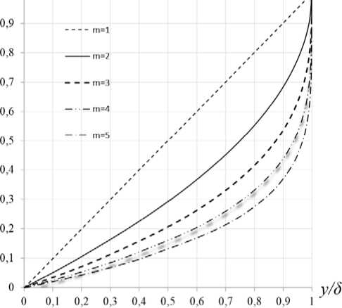
Fig. 1. Distribution of laminar flow velocity profiles
Рис. 1. Распределение профилей скорости ламинарного течения потока
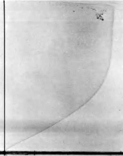
Fig. 2. The velocity distribution profile of the laminar boundary layer
Рис. 2. Профиль распределения скорости ламинарного пограничного слоя
When considering the case of the working fluid flow in the channel between the rotating disk and the fixed wall, it is necessary to take into account the stream core angular velocity and the disk. If the circumferential component of the absolute flow velocity on the wall is
Uw = mcR , then the circumferential friction stress on the wall is defined as
5 „ w = D 1—- R 5, Re c 5
where
8 m ( 47 m 2 + 12 m + 1 )
^^^^.
т 0.293 p ( m c R ) 2 "’ RC
I V
-0.5
.
If the circumferential component of the flow velocity on the disk is
ud = ( m d - m c ) R , then the circumferential friction stress on the disk will be equal to
< = 0.293 p [ ( m D
^^^^^^B
mc)R]2[ ^D
^^^^^^B
V
mc ) R^. Y0.5 — Y D I
.
The considered case refers to the flow at which the distribution of the circumferential velocity component U corresponds to the equation — = m = const.
The thickness of the pulse loss in the circumferential direction with an arbitrary profile degree for the laminar flow wall can be defined as
0.4 0.80.2
I 2
Saw = 0.04535 ---------- I + | I-| R 0.6
a w I 1 + H J IJ LJImJ
.
After transforming this equation, the thickness of the loss of momentum in the circumferential direction on the wall for laminar flow is obtained
^^^^b
D 1 = 0.04535
x
( 3 m + 1 ) 2 ( 5 m + 1 )
14 m ( m + 1 ) ( 7032 m 4 + 2602 m 3 + 413 m 2 + 32 m + 1 ) ( 3 m + 1 )( 4 m + 1 )( 5 m + 1 )( 6 m + 1 )( 7 m + 1 )( 8 m + 1 )
+ 1
2 ( 3 m + 1 )( 4 m + 1 )( 5 m + 1 ) ( m + 1 )( 47 m + 1 )
( 3 m + 1 )( 4 m + 1 )( 5 m + 1 )( 6 m + 1 )( 7 m + 1 )( 8 m + 1 )
0,8
.
x
2 m ( m + 1 ) ( 7032 m 4 + 2602 m 3 + 413 m 2 + 32 m + 1 )
The thickness of the momentum loss in the circumferential direction with an arbitrary degree of profile for a disk with a laminar flow is
0.8
**
°a D =
0.01256
( 1 + H ) J
+
JL
0.2
- I R 0.6
m J
.
^ 3 LJ + 4 L ( K - 2 J )
Further, the thickness of the momentum loss in the circumferential direction on the disk is obtained as
^ = D 2
1 1 R 45 ,
Re5
D—С where
0,8
The velocity profile distribution m for practically important cases is summarized in tab. 2 for the frictional stresses of the laminar flow.
The friction coefficient equation for the wall and disk of the impeller with a laminar flow is expressed as
= т R 2
Lfr p Re2 v 2.
Then the friction coefficient for the wall in the circumferential direction with a laminar flow is defined as
0.0185
D 2 =
2 ( 3 m + 1 )( 4 m + 1 )( 5 m + 1 )
( m + 1 )( 47 m + 1 )
( 3 m + 1 ) ( 4 m + 1 )( 5 m + 1 )( 6 m + 1 )( 7 m + 1 )( 8 m + 1 ) 2 m ( m + 1)(7032 m 4 + 2602 m 3 + 413 m 2 + 32 m + 1
( m + 1) I 2 m + 1 + 1 I (47 m + 1)
V m )
8 m ( m + 1) f ( m + 1)(47 m + 1) 2 m (47 m 2 + 12 m + 1 ) (3 m + 1)(5 m + 1) V (4 m + 1) (3 m + 1) )
x ( 7032 m 4 + 2602 m 3 + 413 m 2 + 32 m + 1 )
(6 m + 1)(7 m + 1)(8 m + 1)
- 6 m ( m + 1) 2 (47 m + 1)(7032 m 4 + 2602 m 3 + 413 m 2 + 32 m + 1 (3 m + 1)(4 m + 1)(5 m + 1)(6 m + 1)(7 m + 1)(8 m + 1)
The velocity distribution profile m for practically important cases (which are realized with laminar flow in the cavity between the impeller and the pump) is summarized in tab. 1.
Taking into account the obtained equations for the impulse loss thickness in the circumferential direction, the tangential friction stresses on the wall for laminar flow are defined as w _ 0.293pv2Re5
T 0a 1 ,
(D1) 2 R R and the laminar disk is defined as
D _ 0.293 pv 2Re D - c
T 0a 1 .
( D 2 ) 2 R R 2
w 0.293
С fr a 1 2
( D 1 ) 2 Re 5
and the friction coefficient for a disk in the circumferential direction with a laminar flow is
D 0.293
С fr a 1 2 .
( D 2 ) 2 Re D - c
Tab. 3 is for coefficient determining of the disk friction and the wall in the circumferential direction with a laminar flow depending on the degree of the velocity distribution profile. This table can be used for engineering calculations convenience m .
The loss coefficient of disk friction during laminar flow is defined as wD
' М С fr a + С fr a .
For the working fluid flow case in the lateral cavity between the working disk and the centrifugal pump housing, the angular core velocity is determined as to c = 0,5 to D . Then the loss of disk friction coefficient laminar flow with laminar flow is defined as
f )
_ 1 0.293 0.293
С М = 2 1 + 1
( 0.5Re D ) 5 V ( D 1)2 ( D 2)2 ?
Tab. 4 is for determining the laminar flow disk friction loss rate and it demonstrates the analysis of the obtained dependence and comparison with obtained results by other authors.
Fig. 3 presents the disk friction coefficient dependence for the laminar flow of the working fluid at Re < 105.
Table 1
Thickness of impulse loss on the wall and disk in the circumferential direction, for practically important cases in laminar flow
|
№ |
m |
** ^ a w |
** ^ a D |
|
1 |
2 |
0.13612 4 1 R 5 |
0.27349 4 1 R 5 |
|
Re c 5 |
Re D — c |
||
|
2 |
3 |
0.20609 4 1 R 5 |
0.44887 4 1 R 5 |
|
Re c 5 |
Re D - c |
||
|
3 |
4 |
0.2708 4 1 R 5 |
0.6382 54 1 |
|
Re c 5 |
Re D — c |
||
|
4 |
5 |
4 0.3321 4 5 1 |
0.83828 4 1 R 5 |
|
Re c 5 |
Re D — c |
Table 2
|
№ |
m |
w τ 0 α |
D τ 0 α |
|
1 |
2 |
8 0.794158 ρν 2 Re c 5 R 2 |
8 0.560269 ρν 2 Re 5 D - c R 2 |
|
2 |
3 |
8 0.645415 ρν 2 Re c 5 R 2 |
8 0.437328 ρν 2 Re 5 D - c R 2 |
|
3 |
4 |
8 0.563045 ρν 2 Re c 5 R 2 |
8 0.366766 ρν 2 Re 5 D - c R 2 |
|
4 |
5 |
8 0.508432 ρν 2 Re c 5 R 2 |
8 0.320017 ρν 2 Re D 5 - c R 2 |
Table 3
|
№ |
m |
w С fr α |
D С fr α |
|
1 |
2 |
0.794158 2 Re c 5 |
0.560269 2 Re5 D - c |
|
2 |
3 |
0.645415 2 Re c 5 |
0.437328 2 Re D 5 - c |
|
3 |
4 |
0.563045 2 Re c 5 |
0.366766 2 Re5 D - c |
|
4 |
5 |
0.508432 2 Re c 5 |
0.320017 2 Re D 5 - c |
Table 4
|
№ |
m |
G. Shlikhting |
Cimbus, K. Smiden |
F. SHul’tc-Grunov |
С М |
|
1 |
2 |
3.87 Re12 |
3.14 R Re z , R = 0.02 (radius to gap ratio) z |
2.67 Re12 |
1.787844 2 Re5 |
|
2 |
3 |
1.429221 2 Re5 |
|||
|
3 |
4 |
1.227351 2 Re5 |
|||
|
4 |
5 |
1.093553 2 Re5 |
Tangential friction stresses on the wall and disk in the circumferential direction, for practically important cases in laminar flow
Friction coefficient on the wall and disk in the circumferential direction, for practically important cases with laminar flow
Disk friction coefficient, for practically important cases with laminar flow
If m = 2 and the gradient function of laminar flow agrees well with the dependence of G. Shlikhting [21], then the maximum deviation of the disk friction parameter does not exceed 7 %. If Re = 103 the difference is 5 %, and if Re = 105 the difference is 7 %. In general, all dependencies are in the region of the confidence span defined by various authors and are in the parameter domain for disk friction coefficients from 0.113 to 0.027, depending on the Re criterion (fig. 3). It is important to note that when designing flow parts it is necessary to choose the turbulence transition which depends on the boundary conditions of the flows.
Fig. 4 shows the dependence on the disk friction coefficients, the friction coefficient for the wall in the circumferential direction and the friction coefficient for the disk in the circumferential direction of the laminar flow required for the flow parts design and for the power balance of low mass flow centrifugal pumps determining.
The radial element of the tangential friction stress is formed by the circumferential and consumable components taking into account the bottom lines slope and leaks through the sealing elements.
Radial stress of friction on the wall is www t0 R = т0 Rp + т0 R а and radial friction stress on the disk is
DDD т 0 R = т 0 Rp + т 0 R а .
Radial stress of friction from the circumferential com- ponent is
Т0Rа ST0a, where s - tangent of the bottom slope angle.
The radial friction stress will be determined depending on the flow rate associated with the amount of leakage through the sealing elements, and the dependence on the structure is similar to straight linear flow t0 = 0.01256pVr2
V r m 8
v ( m + 1)( m + 2)
-0.25
where V р – flow rate.
The one side resistance moment of the low mass flow centrifugal pump working disk is defined as
R 2
M D = 2 n J Т 0а r 2 dr = С М P R 5 ® D .
R 1
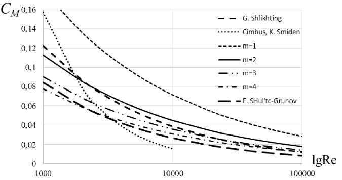
Fig. 3. Coefficient of disk friction laminar flow
Рис. 3. Коэффициент дискового трения ламинарного течения
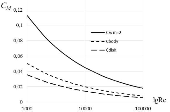
Fig. 4. Coefficient of disk friction
Рис. 4. Коэффициент дискового трения
Then the impeller disk friction power on one side of the low mass flow centrifugal pump is defined as
N frD = M D ® D .
Conclusion. The analysis of low mass flow centrifugal pump operating parameters used in aircraft and spacecraft power systems was carried out. After analysing the working fluid characteristics and the temperature range, it was revealed that a laminar rotational flow with Reynolds numbers Re = 10 3 ^ 3 - 10 5 is conducted in the cavity between the impeller and the pump.
The method for determining the power losses due to disk friction of the impeller with design features and the applied schemes was developed. The equations for disk friction coefficient determining are consistent with the results of other authors. The obtained equations for the laminar rotational flow established mathematical dependencies to determine the resistance moment and power of the impeller disk friction of a low mass flow centrifugal pump.
References The method of the disk friction determining of low mass flow centrifugal pumps
- Valentini, D., Pace, G., Pasini, A., Torre, L., Hadavandi, R., d’ Agostino, L. (2017). Fluid-induced rotordynamic forces on a whirling centrifugal pump. European Journal of Mechanics – B/Fluids, 61, Р. 336–345. Doi: 10.1016/j.euromechflu.2016.09.004.
- Liu, M., Tan, L., Cao, S. (2019). Theoretical model of energy performance prediction and BEP determination for centrifugal pump as turbine. Energy. Doi: 10.1016/j.energy.2019.01.162.
- Sengpanich, K., Bohez, E. L. J., Thongkruer, P., Sakulphan, K. (2019). New mode to operate centrifugal pump as impulse turbine. Renewable Energy. Doi: 10.1016/j.renene.2019.03.116.
- Ding, H., Li, Z., Gong, X., Li, M. (2018). The influence of blade outlet angle on the performance of centrifugal pump with high specific speed. Vacuum. Doi: 10.1016/j.vacuum.2018.10.049.
- Skrzypacz, J., Bieganowski, M. (2018). The influence of micro grooves on the parameters of the centrifugal pump impeller. International Journal of Mechanical Sciences, 144, Р. 827–835. Doi: 10.1016/j.ijmecsci.2017.01.039.
- Zhang, N., Liu, X., Gao, B., Wang, X., Xia, B. (2019). Effects of modifying the blade trailing edge profile on unsteady pressure pulsations and flow structures in a centrifugal pump. International Journal of Heat and Fluid Flow, 75, Р. 227–238. Doi: 10.1016/j.ijheatfluidflow.2019.01.009.
- Chen, H., He, J., Liu, C. (2017). Design and experiment of the centrifugal pump impellers with twisted inlet vice blades. Journal of Hydrodynamics, Ser. B, 29(6), Р. 1085–1088. Doi: 10.1016/s1001-6058(16)60822-3.
- Yu, R., & Liu, J. (2018). Failure analysis of centrifugal pump impeller. Engineering Failure Analysis, 92, Р. 343–349. Doi: 10.1016/j.engfailanal.2018.06.003.
- Salehi, S., Raisee, M., J. Cervantes, M., Nourbakhsh, A. (2018). On the flow field and performance of a centrifugal pump under operational and geometrical uncertainties. Applied Mathematical Modelling, 61, Р. 540–560. Doi: 10.1016/j.apm.2018.05.008.
- Bobkov A. V. [The influence of the factor malorazmernyj to the design of the supercharger centrifugal type]. Uspekhi sovremennoy nauki. 2017. Vol. 4. No. 2. P. 127–130 (In Russ.).
- Bobkov A. V. [A geometric criterion of optimizing the design of blade machines]. Mezhdunarodnyy zhurnal prikladnykh i fundamentalnykh issledovaniy. 2013. No. 6. P. 49 (In Russ.).
- Bobkov A. V. [Energy expediency of increasing the number of stages in a small centrifugal electric pump unit]. Sovremennyye problemy nauki i obrazovaniya. 2012. No. 4. P. 84 (In Russ.).
- Bobkov A. V., Tsvetkov E. O. [Improving the pressure qualities of the centrifugal pump thermal control system]. Mezhdunarodnyy zhurnal prikladnykh i fundamentalnykh issledovaniy. 2012. No. 10. P. 110 (In Russ.).
- Bobkov A. V., Tsvetkov E. O. [Features of balance of power losses in electric pump units of spacecraft thermal control systems]. Izvestiya Samarskogo nauchnogo tsentra Rossiyskoy akademii nauk. 2011. Vol. 13. No. 1–2. С. 290–292 (In Russ.).
- Dvirnyy V. V., Krushenko G. G., Golovanova V. V., Dvirnyy G. V., Petyayeva N. N., Kirianova K. A. [Improvement of units for heat transportation in spacecraft]. Issledovaniya naukograda. 2016. No. 3–4 (18). P. 12–16 (In Russ.).
- Dvirnyy V. V., Dvirnyy G. V., Khnykin A. V., Golovanova V. V., Krushenko G. G. [Providing long lasting resource of economical compressors]. Issledovaniya naukograda. 2014. No. 3 (9). P. 12–20 (In Russ.).
- Krayeva E. M. [Energy parameters of high-speed low-flow pumps]. Vestnik Moskovskogo aviatsionnogo instituta. 2011. Vol. 18. No. 3. P. 104 (In Russ.).
- Krayeva E. M. [Calculation of energy parameters of high-speed centrifugal pumps of low speed]. Izvestiya vysshikh uchebnykh zavedeniy. Aviatsionnaya tekhnika. 2010. No. 1. P. 48–50 (In Russ.).
- Krayeva E. M. [To calculation of operating parameters of centrifugal pumps of low speed]. Vestnik SibCAU. 2009. No. 2 (23). P. 168–170 (In Russ.).
- Bobkov A. V., Katalazhnova N. I., Kachalov A. A. [TCalculation of field lines ratio specific speed centrifugal blower spacecraft]. Uspekhi sovremennogo estestvoznaniya. 2004. No. 4. P. 50–51 (In Russ.).
- Shlikhting G. Teoriya pogranichnogo sloya [The theory of the boundary layer]. Moscow, Science Publ., 1974. 712 p.
