The possibilities for optimizing the functional system structure of civil aviation aircraft

Author: Furmanova E.A., Boiko O.G., Shaimardanov L.G.
Journal: Сибирский аэрокосмический журнал @vestnik-sibsau
Section: Математика, механика, информатика
Article in issue: 7 (33), 2010.
Free access
This is an analysis of the traditional approach to systems with individual reserving reliability calculation usage. An alternative calculation method for these systems with an individual reserve system has been developed. Its application is demonstrated.
Functional systems, analysis of the complicated systems, system structure optimization
Short address: https://sciup.org/148176465
IDR: 148176465
Text of the scientific article The possibilities for optimizing the functional system structure of civil aviation aircraft
The airplanes functional systems execute many important functions: make the planer’s steering surfaces drive by mechanization means, provide the aviation engines fuel supply, provide the cabin air pressure and air conditioning in them, provide all the consumers with electricity, protect the airplane from ice, provide fire extinguishing functions, provide automatic piloting, and air navigation.
The functional systems of the same type on all the route airplanes execute the same functions. At the same time, systems with the same name from different developers, or one developer, which is seen more often, on different types of aircraft, may have a different functional systems structure. With the same development in machine building, which provides a similar level of aggregate systems reliability, the reservation level is different in individual and typical aircraft system types with the same name.
Such a position is connected with the absence of research in the field of the system’s optimization structure.
The proposed study shows the possibilities of common and individual reserving in the reliability securing systems.
Let’s look through the individual reserving system, which contains n units that are successively linked. Each of the units includes m = 2 aggregates connected parallel. The structural scheme of such system is shown in the fig. 1.
Let’s think that all the aggregates have the same breakdown stream parameters ω .
Let’s consider for a mathematical model of the aggregate’s breakdown probabilities the distribution with an even density probability. Then, the aggregate breakdown probability integral function will be:
q(t) = to-1.
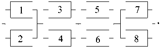
Fig. 1. The individual reserving system structural scheme
If t = 1, then we can find the breakdown probability for 1 flight hour:
q = to .
In the traditional approach of the reliability calculation, the first thing we had to do was defining the breakdown probability for parallel switched units at the aggregates:
q s = to 2 .
Their working probability without breakdown [1; 2]:
P8 = 1 -to2.
So, the initial system, exchanges with the system with successively connected elements, and their without breakdown work probabilities equal P s . And then we define the initial system breakdown probability:
Q C = 1 - ( 1 -to 2 ) n . (1)
Breakdown probability of the system with successively connected units increases with increasing of unit’s quantity n .
In reality it is not so. The initial system (fig. 1) will break down only if in one of the units (any) both aggregates will fail. Because the aggregate’s breakdown probabilities in 1 hour are identical and equal to to , various scenarios of the aggregate’s breakdown are possible, which will not lead the system to breakdown. For example, aggregates 1, 2, 6, 7 will fail (it doesn’t matter in what succession order). The more n is, the less will be the breakdown probability of 2 aggregates in one unit. Any aggregate of the system may fail first with a probability of to . The probability of the fact that the aggregate, based in one unit with the first, will fail equals to:
1 to .
2 n - 1
Then the studied system breakdown probability during the proposed alternative approach to systems with individual reserving calculations will be:
Qc(n )=2. (2)
Such an expression defines the most probable breakdown. Other possible scenarios of breakdown development in the system define essentially less breakdown probabilities due to:
QCi( n ) = "7——-----• (3)
П ( 2 n -j- 1 )
J ' =2
where i – is the quantity of broken aggregates, which lead the system to breakdown during the observed breakdown development scenario.
It’s important to highlight the fact that during the increase of quantity n for successively connected units, breakdown probability according to (2) and (3) decreases, not increases, as the traditional approach shows (1).
The developed technique for systems with reserving reliability calculation allows changing the opinion of the system’s reliability possibility increase; changes in the approach allow the usage the combination of common and individual reserving.
Let’s view a system, consisting of two parallel working undersystems. The undersystems each contain 16 successively connected aggregates (fig. 2).
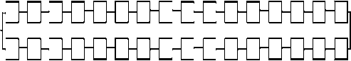
Fig. 2. The common reserving system
The breakdown probability of such a system may be defined as:
Q^ = [ 1 - ( 1 -to ) 2 ] *6 , (4)
where n = 16 – is the number of successively connected aggregates; m = 2 – is the number of undersystems, connected in a parallel way; to = 0.01 is breakdown flow parameter; the same is for all aggregates.
We shall not change the number of the aggregates in the system and its level of reserving. Let’s divide the system into z parts, which will be connected successively (fig. 3).


Fig. 3. The initial system divided into z = 4 parts of the common reserving
Let’s account the reliability level for such a system. The probability of breakdown for each branch for any of the 4 parts will be:
Q = 1 -( 1 -to) 4 .
Then the system (fig. 3) shall be transformed into.
In this system, the breakdown probability of each element equals to Qв and it is defined according to (5). The first and the largest system breakdown probability (fig. 4) is realized when 2 elements in one unit fail. It will be defined as:
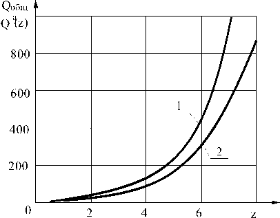
Fig. 6. The dependence of breakdown relation probabilities for the initial system and the breakdown probability of the system, divided into z parts and calculated according to the alternative technique from z , with n = 16, m = 2;
1 - ю = 1 x 10 - 5 and 2 - ю = 10 - 2
Q a ( - ) =y.
Fig. 4. The essential system, divided into z = 4 parts and transformed into the individual reserving scheme
We completed the breakdown probabilities calculations, during common reserving and after division into z parts, in accordance to the traditional and
Q общ
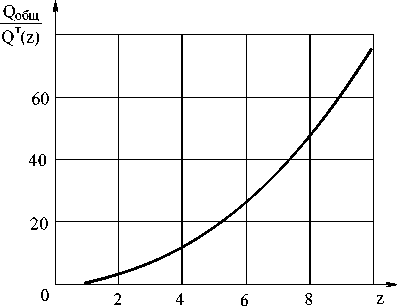
Fig. 7. The dependence of the initial system relation breakdown probabilities from a system divided into z parts and calculated according to the traditional technique breakdown probability from z . With n = 20, m = 3, and ю = 1 x 10 - 2
alternative method. The dependences of c and Q ( a z )
Q общ
-
c on z are shown in the fig. 5–8.
Q ( T z )
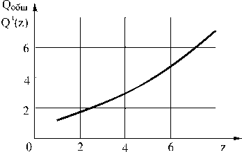
Fig. 5. The dependence of relation for the common reserving initial system breakdown probability and the breakdown probability of the system, divided into z parts from z , applying the standard technique n = 16, m = 2 and ю = 1 x 10 - 2
From fig. 5 we can conclude that the calculations, made according to the traditional approach, show us the common reserving system reliability increase, during its division into z parts. This will transfer the system into a system containing z units with individual reserving. However, this reliability increase is not much: at z = 2 it is 1,8 times, and at z = 4 it is 3,5 times greater.
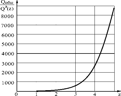
Fig. 8. The dependence of initial system breakdown relation probabilities from the breakdown probability of a system, divided into z parts and calculated according to the alternative technique from z , with n = 20, m = 3, ю = 1 x 10 - 2
The transference of a system with a common reserving to a system with z units of individual reserving is linked to some difficulties. We shall try to explain them further. A slight increase in reliability didn’t stimulate the system developers to overcome the stated difficulties.
Applying the alternative method for the same task of the reliability increasing solution dividing the system into z parts, the reliability is greater (fig. 6). With z = 4 achieving 100 and with z = 6 – (340–400) times.
For a system with common reserving, with 3 undersystems working parallel the effect is much greater. In the traditional approach the reliability calculation has a 12 time reliability increase during z = 4 (fig. 7), and for the alternative approach (fig. 8) the reliability increases by 2.800 times, for z = 5 by 9.000 times.
This may stimulate the developers to overcome the earlier highlighted difficulties, which are connected with the transference of systems with a common reserving to systems with z units of individual reserving.
Let’s shortly characterize these difficulties. In the hydraulic system, which consists of 2 identical undersystems, the pipe-line gap or one of the aggregate’s core gaps leads to the loss of the entire hydro-liquid undersystem. The second undersystem remains intact and will provide the entire hydro-system’s function execution. The changing of a systematical scheme, which would lead it to z units of individual reserving, deprives it of such protection. The undersystems are joined into one and the loss of liquid in one branch of the system’s z-part will result in the loss of liquid in the whole system; this is inadmissible. Here it is possible to apply some of the blocking measures. In each branch of the z-part of the system, an expenditure measuring unit should be installed; in the beginning of a system a shutdown valve should be installed, and at the end of the system a reverse valve should be installed. During some flight time there is no liquid loss in the system. Such loss is displayed as pressure loss. The expenditure gauge sends a signal and the shutdown valve closes. The reverse valve eliminates the liquid expenditure. The shutdown valve blocks itself during the functioning of the usual consumers, which have some liquid expenditure during their functioning.
For electric systems the labor saving provisional system is much simpler. There are two kinds of malfunctions in the electric system: it is unnecessary to block the circuit in one of the z -part branches. It stops working and the entire load is transferred to a parallel branch of the z -part. In order to block the influence distribution of short-circuiting on one of the z -part branches on previous system parts, in the beginning of each z -part branch it is necessary to have a network protection device (a fuse).
