The possibility analysis of power increase efficiency in generating devices for onboard radio-electronic means

Author: Mikheenko A.M., Abramov S.S., Rezvan I.I.
Journal: Сибирский аэрокосмический журнал @vestnik-sibsau
Section: Авиационная и ракетно-космическая техника
Article in issue: 5 (26), 2009.
Free access
A generalized analysis of a high frequency key generator is conducted. This analysis allows the power indicators estimation of the generator in a wide frequency range, and in scheme parameters.
Key generator, on-board system, resonance inverter
Short address: https://sciup.org/148176105
IDR: 148176105
Text of the scientific article The possibility analysis of power increase efficiency in generating devices for onboard radio-electronic means
In the issues of space development there is an important one of power supply maintenance for independent objects; these objects are intended for long-term presence in orbit or in interplanetary space. One of the working capacity maintenance ways of long-term space objects is the increase in power efficiency for the basic consumers – onboard electronic systems. This particularly concerns powerful generating devices for communication purposes.
For powerful radio devices the biharmonic mode generator had been widely used. With the advent of powerful solid-state electronics application, duple schemes of consecutive resonant inverters (class generators “D”) [1] came into exploitation.
The possibility of energy conversion efficiency increase with an upset loading, was discovered by E. P. Khmelnitskiy in the 1960s [2]. In foreign sources, generators of such type were known as class E generators, as in Russian they were identified as key generators with a forming contour [3]. Despite the fact that class E generators provide high energy conversion efficiency for limited key modes frequencies, in a variety of causes their application is limited, and they are still on the stage of experiment. The scheme analysis for a wide range of frequencies and scheme parameters generally, has a lower result.
A simplified scheme of the generator is presented in figure 1, where AE is the active element (transistor, lamp) working in the key mode; VD is a diode that provides recuperation of energy of jet elements in an opened key; L , C are the elements of a contour, defining the form of pressure on AE; Lk , Ck are the loading contours, which have been adjusted to the frequency of operating pressure.
Supposing, that the unlocking and locking of AE is completely defined the by operating pressure ( Uk ), we will present the investigated generator in two equivalent schemes; they will show the processes happening in the generator in open and closed conditions of the AE. Here u = U sin (τ+ϕ); τ = ϕ t ; 2θ – an angle corresponding to the time during which theAEisopen; iL 1, iL – currents in the external chain of the generator for corresponding equivalent schemes.
The differential equation for equivalent schemes becomes:
d 2 i 1 di
2 L + L +ν2
d τ2 r ω C d τ
ν2 E - U k ( r
ν2sin(τ + ϕ) r
cos( τ + ϕ ) ω L ),
d 2 i
L 1 +ν2 i = d τ2 L 1
U
- k cos(τ+ϕ). ω L
The solution for these equations can be written down the following way:
i =σ+ξε1 cos(τ + ϕ) -
-ξε2sin(τ+ϕ)+ I 11 ep 1τ+ I 12 ep 2τ..., (3)
i 1 = I 21 cosν(τ -2θ) +
+ I 22 sinν(τ -2θ) - ξcos(τ + ϕ), (4)
ν2 -1
U = -ξε1 sin(τ + ϕ) --ξε2cos(τ + ϕ) + p 1 I 11 ep 1τ + p 2 I 12 ep 2τ,
U 1 = ν I 22 cosν(τ -2θ) -
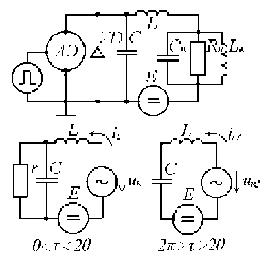
Fig. 1. Scheme of the generator
-ν I 21 sinν(τ -2θ) +
1 ν2 -1
ξsin(τ + ϕ).
The following designations are accepted here: i = i ω, L E
ω L Ldi L di 1
i 1= iL 1 , u = L , u 1= L 1, p 1= - ,
1 L 1 E , Ed τ , 1 Ed τ1ω rC ,
p 2 = - 1 – roots of the σ
characteristic equation (1);
2 1 ω L U
ν2 = 2 , σ = , ξ= ,
ω2 LC r E
σν4
ε 2 = p 12 + ( ν 2 - 1)2, I 11, I 12, I 21, I 22 -
ε1
p 1 2-(ν2-1) p 1 +(ν2-1)2
integration constants.
Supposing that the generator mode had been established, we will define the integration constants, using the current continuity principle in inductance and in capacity pressure of contour LC:
i (0) = i 1(2π); i (2θ) = i 1(2θ), uc = uc 1(2π); uc (2θ)= uc 1(2θ)
Here U = E - U - U .(9)
ckL
On the basis of (3)–(6) in conditions (7)–(9) we will receive:
I 11 = A 1 + ξ( B 11sinϕ + B 12cosϕ);
I 12 = A 2 +ξ( B 21sinϕ+ B 22cosϕ);
I 21 = A 3 +ξ( B 31sinϕ+ B 32cosϕ);
I 22 = A 4 +ξ( B 41sinϕ+ B 42cosϕ).
For the definition of the generator’s power indicators it is necessary to define the current of the first loading harmonic and the current consumed from the power supply.
I 1 = I 1 2 s + I 1 2 c = I 1 s = I 1 c , tg ϕ = I 1 c . (11) cos ϕ sinϕ I 1 s
Here:
2θ
In the last expressions the following designations are accepted:
A 1
a 2 b 3 a 1 b 2
-
-
a 3 b 2
a 2 b 1
a 3 b 1
a 1 b 2
-
-
a 1 b 3 ; a 2 b 1
B
B 21 = a 1 b 2
a 1 =1- e 2 p 1θcos2ν(π-θ)
- a41b2 ;
a 2 b 41
B 22 =
B 12 =
|
a 1 b 2 |
- a 2 b 1 |
|
a 2 b 42 |
- a 42 b 2 |
|
a 1 b 2 |
- a 2 b 1 |
|
a 42 b 1 |
- a 1 b 42 |
|
a 1 b 2 |
- a 2 b 1 |
|
a 41 b 1 |
- a 1 b 41 |
;
;
-
-
a 2=1- e 2 p 2θcos2ν(π-θ)-
a 2 b 1
p1 e2p1θ ν p1 e2p2θ
sin2ν(π - θ);
sin2ν(π - θ);
ν a3 =σ[1-cos2ν(π-θ)];
a41 =-ε2 +q1cos2ν(π-θ)+1 q2sin2ν(π - θ); ν a42 =ε2 -q2cos2ν(π-θ)+1 q1sin2ν(π - θ);
b 1 =- p 1 [1- e 2 p 1θ
b 2 =- p 2 [1- e 2 p 2θ
ν cos2ν(π-θ)+p2e2p1θ ν cos2ν(π-θ)+p1e2p2θ ν
sin 2ν(π - θ)];
sin 2ν(π - θ)];
p 1 b 3=- 1sin2ν(π - θ); ε3= ε1+ ;
3 ν 31 ν 2 - 1
b 41 =ε2 - q 1cos2ν(π-θ)+ν q 2sin2ν(π-θ);
|
A 3 |
=σ+ A 1 e 2 p 1θ + A 2 e 2 p 2θ ; |
|
A 4 |
= p 1 A 1 e 2 p 1θ + p 2 A 2 e 2 p 2θ |
|
νν |
|
|
B 31 |
= B 11 e 2 p 1θ + B 21 e 2 p 2θ - q 1 ; |
;
q 2;
;
q 1=(ε3sin2θ+ε2cos2θ);
B 32 = B 12 e 2 p 1θ + B 22 e 2 p 2θ
-
q 2=(ε3cos2θ-ε2sin2θ);
B 41 = 1 ( p 1 B 11 e 2 p 1θ+ p 2 B 21 e 2 p 2θ ν
B 42 = 1 ( p 1 B 12 e 2 p 1θ+ p 2 B 22 e 2 p 2θ
-
q 2);
-
q 1).
ν
Substituting the values of integration constants (10) in equations (3)–(6), we will receive the description of an inductance current and pressure for the established generator mode.
1 2θ 1 I 1 s = iL sinτ d τ+ ππ
2π
∫ iL 1sin τ d τ =
2θ
E 2θ2π =( ∫ i sinτ d τ+ ∫ i 1sinτ d τ)= πω L 02 θ
= E [ A 5+ξ( B 51sinϕ+ B 52cosϕ)]; πϖ L
1 2θ 1 2π
I 1 c = iL cosτ d τ+ iL 1cosτ d τ=
π 0 π 2θ
= E [ A 6+ξ( B 61sinϕ+ B 62cosϕ)]. πϖ L
Parameters A 5, A 6, B 51, B 52, B 61, B 62aredefinedbythe following expressions:
1 A
A 5 =[σ(1-cos2θ)+1 d 12 +
5 π 1+ p 1 212
+ 1 ( A 3 d 13 + A 4 d 14 )];
ν2 -1
B 51 = ν 2
+ B 11 1+ p 1 2
1 2 - 1
+ 1 [ε3(
d 11 +
π B 21 1+ p 2 2
B 52 = [ε2( π
B 11 d
1+ p 1 211 d 11
B 61
B 11 1+ p 1 2
B 62
B 12
sin4 θ cos4 θ 1
-θ)+ε (-)+ 4244
d 12 + 1 ( B 31 d 13 + B 41 d 14 )];
12 ν 2 - 1 31134114
sin 4θ 4
-
θ)-ε( cos4 θ- 1
B 22 d 12 + 1 ( B 32 d 13 + B 42 d 14)];
1+ p 22ν2-1
=1- e 2 p 1θ
d 12 =1- e 2 p 2θ
(cos2θ - p 1sin2θ);
(cos2θ - p 2sin2θ);
d 13 =cos2ν(π-θ)-cos2θ;
d 14 = sin2ν(π - θ) + νsin2θ;
1 A
A 6=[σsin2θ+1 d 21 + π 1 + p 1 2
A 2 1
d 22 + 1+ p 2222 ν2-
= 1 [ε3( π
cos 4θ 4
-
( A 3 d 23 + A 4 d 24 )];
1 sin4 θ
4)-ε 2 (4+θ)+
d 21
1 ν2-1
1+ p 1 2
B 21 1+ p 2 2
d 22 +
+ 1 [ε 2 (
d 21 +
π B 22 1+ p 2 2
ν sin 4θ 4
21 ( B 31 d 23 + B 41 d 24)];
-1
cos4 θ 1 +θ)+ε 3 (4-4)+
d 22 + ( B 32 d 23 + B 42 d 24 )];
ν2 -1
d21 = -p1+e d22 = -p2+e
2 p 1θ
2 p 2θ
( p 1cos2θ +sin2θ);
( p 2cos2θ +sin2θ);
d 23 =νsin2ν(π-θ)+sin2θ;
d 24 =cos2θ- cos2ν(π - θ).
The electricity consumed from the source:
12θ U 12θ E - U - U
I 0= cd τ = kL ×
2π0 r 2π0 r
E 2θ
× d τ = a σ[1-ξsin(τ+ϕ)- u ] d τ
2πω L 0
U is defined by expression (5).
Result of the integration (14):
I 0= Ea σ{2θ+ξ[cos(2θ+ϕ)-cosϕ](1-ε1)+
2πϖ L
+ξε2[sin(2θ + ϕ) -sinϕ] +
+ I 11 (1- e 2 p 1θ)+ I 12 (1- e 2 p 2θ)}.
The efficiency of the first harmonic is defined by the known parity [3]
1 I
η =ξ1.
2 I 0
Asξ=Uk=I1R=I1sR, EEcos ϕ thatagrees ξ=R [A5+ξ(B51sinϕ+B52cosϕ)] ωLcos ϕ
.
On the other hand, tgϕ =I1c=A6+ξ(B61sinϕ+B62cosϕ)
I 1 s A 5 +ξ( B 51 sinϕ+ B 52 cosϕ)
.
The system of the transcendental equations (17), (18) allows us to define the required value of .
From the conducted analysis we can see, that direct calculations of the generator’s power indicators are rather labor-consuming, because of the bulky calculations and the impossibility of an analytical solution for this system of equations (17), (18).
Therefore in each separate case it is expedient to resort numerical methods by using computer calculations.
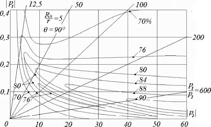
As an example, we have executed the PEVM energy conversion efficiency calculation. The generator for the special case is 9 = 90° and R H = 5r.
Figure 2 shows the generator’s energy conversion efficiency dependence from the frequency and the LC contour parameters on a plane of variables ( 1, 2).
As a first approximation p1≈1C ; p2=rL; ω1 ωr ω p1p2=0; ω0= .
ω LC
In the frequency characteristics of the generator’s energy conversion efficiency it is possible to receive surface construction planes (figure 2), corresponding to specific p 2
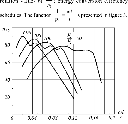
Fig. 3. Frequency characteristics of the generator
Here as in figure 2, the special case 9 = 90° and R H =5r is considered.
The conducted analysis states that direct calculations of the generator’s energy features are rather complicated. The reason for this is the excessive calculation size and the analytical impossibility of solving equation systems (17), (18).
It is advisable to use numerical methods together with calculating devices for each case.
In conclusion we can say that it is possible to considerably increase the generator’s energy conversion efficiency; in comparison with standard power converters, the energy conversion efficiency of which does not exceed 40...60 % for high frequencies.