The power circuit of mechanical damping device for cooling system of 50 kW pulse diesel generator

Author: Wang Yu., Mindrov K.
Journal: Бюллетень науки и практики @bulletennauki
Section: Технические науки
Article in issue: 6 т.10, 2024.
Free access
Diesel generators have advantages such as high reliability, superior economic performance, and a wide range of applications. However, its working environment is relatively sealed, and it is difficult for the internal heat of the motor to transfer to the outside. Prolonged high temperatures can affect the operational performance of the motor and even cause danger. Therefore, it is necessary to design a reasonable cooling system to ensure its efficient operation within the safe working temperature. The water-cooled cooling system has good heat dissipation performance, consisting of components such as a water pump, radiator, fan, water tank, and temperature controller. By precisely controlling the water flow rate and wind speed, effective control of the internal temperature of the generator is achieved, extending the service life of the equipment. This article studies the power circuit of the mechanical damping device in the cooling system of a 50kW pulse diesel generator, develops heat transfer and hydraulic energy circuits, and constructs the frequency response of the circuit. As the water quality increases in the circuit, the amplitude decreases at low frequencies (less than 4 rad/s) and frequencies close to 10 rad/s, and the amplitude aligns. For one parameter variable, the optimal frequency is 3-4 rad/s.
Diesel generator, cooling system, frequency response
Short address: https://sciup.org/14130494
IDR: 14130494 | UDC: 621.311.236 | DOI: 10.33619/2414-2948/103/42
Силовая цепь механического демпфирующего устройства системы охлаждения импульсного дизель-генератора мощностью 50 Квт
Дизельные генераторы имеют преимущества высокой надежности, превосходных экономических характеристик и широкого спектра применений. Однако его рабочая среда относительно герметична, и тепло внутри двигателя трудно передать наружу. Длительные периоды высоких температур могут повлиять на работоспособность двигателя и даже создать опасность. Поэтому необходимо разработать рациональную систему охлаждения для обеспечения ее эффективной работы при безопасной рабочей температуре. Система с водяным охлаждением обладает хорошими теплоотводящими свойствами и состоит из насосов, радиаторов, вентиляторов, резервуаров для воды и регуляторов температуры и других компонентов. Благодаря точному управлению потоком воды и скоростью ветра обеспечивается эффективный контроль внутренней температуры генератора, что продлевает срок службы оборудования. В этой статье изучается схема мощности механического демпфирующего устройства в системе охлаждения импульсного дизельного генератора мощностью 50 кВт, разрабатываются схемы теплопередачи и гидравлической энергии, а также строится частотная реакция схемы. По мере увеличения качества воды в контуре амплитуда уменьшается при низких частотах (менее 4 Рад/с) и частотах, близких к 10 Рад/с, и амплитуда выравнивается. Для параметрической переменной оптимальная частота составляет 3-4 рада/с.
Text of the scientific article The power circuit of mechanical damping device for cooling system of 50 kW pulse diesel generator
Бюллетень науки и практики / Bulletin of Science and Practice
UDC 621.311.236
A diesel generator is a type of power generation equipment that uses diesel as fuel and diesel engines as prime movers to drive the generator to generate electricity. Its working principle is that the diesel engine sprays diesel fuel into the intake duct through an injection pump, mixes it with the air entering the cylinder, and after high-pressure and high-temperature combustion, produces high-pressure gas, which drives the piston to move and drives the crankshaft to rotate, thereby driving the generator to generate electricity. The components of a diesel generator include a diesel engine, generator, cooling system, fuel system, and electronic control system. Each component has its specific function, and they work together to achieve the normal operation of the diesel generator.
With the rapid development of the national economy, the total consumption of electricity in the country continues to rise, and shows a diversified development trend, especially in the areas of mobile power, emergency power, and fire power, where demand is gradually increasing. As conventional backup power supply equipment, diesel generators have many advantages.
High stability: As an independent power generation system, diesel generators are not affected by power grid issues and have independent and stable power supply capabilities. At the same time, in environments with significant load changes, the diesel engine speed can be adaptively adjusted, ensuring a stable supply of electrical loads and high power quality [1].
Quick start: The diesel generator starts quickly and does not require hot standby. It usually only takes a few seconds to start, and the operation method is simple and easy to control. In emergency situations, it can quickly supply power and ensure the normal use of electricity.
Economy: Compared to other power supply methods, diesel generators, as intermittent working equipment, have much lower fuel consumption than automotive diesel engines and higher thermal efficiency. Compared to gasoline engines, they can generate more driving force with the same mass and volume, making them more economical [2]. On the one hand, the maintenance and operation costs of diesel generators are relatively low. On the other hand, it has the advantage of an independent power supply system, which can continue to provide electricity security for users even in the event of a power outage.
Wide applicability: Diesel generators can choose different power units according to different needs. It is suitable for various weather and geographical environments and can provide power 24/7. Meanwhile, because it can use fuels such as diesel, natural gas, and even biogas, it can meet various environmental needs and fully demonstrate its applicability [3].
At present, there are various types of diesel generators on the market, which can meet a wide power range. However, diesel engines are highly heat generating power equipment, and approximately 30% of the heat generated by diesel generators during operation is absorbed by the engine body components [4]. Due to the direct connection between the generator and the diesel engine, the generator operates in a relatively high temperature environment. Moreover, diesel generators operate in a relatively sealed working environment, making it difficult for the internal heat of the motor to transfer to the outside, resulting in a sharp increase in motor temperature rise. If the body components are not cooled in a timely manner, their material properties will significantly decrease [5]. At the same time, due to temperature expansion, the fitting relationship between components will be damaged, increasing their wear and even leading to shutdown and jamming [6]. Therefore, considering that prolonged high temperatures can affect the operational performance of the motor and even pose risks, it is necessary to design a reasonable cooling system to suppress the temperature rise of the motor and ensure its efficient operation within the safe working temperature. In order to better study the diesel engine cooling system, the power circuit of the device was drawn and the frequency response of the circuit was constructed. By mathematical transformation of the power circuit, complex impedance, frequency function, amplitude frequency characteristics, and phase frequency characteristics were obtained.
Cooling system composition and thermal principles
The cooling system of a diesel generator consists of multiple components such as a water pump, coolant tank, heat exchanger, temperature sensor, etc. The circulating coolant absorbs and transfers the heat generated by the generator to ensure that the temperature of the generator is within a safe range [7]. The water pump is the core component of the liquid cooling system, responsible for extracting coolant from the coolant tank and delivering it through pipelines to the radiator of the generator. Water pumps are usually driven by electric motors or engines to ensure sufficient coolant flows through the generator [8]. The coolant tank is a container for storing coolant. It is usually located near the generator and can accommodate enough coolant to meet the needs of the entire liquid cooling system. The coolant tank also has a coolant settling chamber for filtering and removing impurities and dirt from the coolant. A heat exchanger is a device used to transfer the heat generated by a generator to the coolant. The coolant exchanges heat with external circulating water inside the heat exchanger to reduce temperature [9]. The temperature sensor is used to monitor the temperature of the coolant and send the data to the generator control system. When the temperature exceeds the set value, the control system can take corresponding measures, such as increasing the coolant flow rate, adjusting the fan speed, etc.
The forms of heat transfer are relatively complex, including three types of heat transfer: heat conduction, heat convection, and heat radiation [10]. However, due to the forced flow of cooling air and coolant, the impact is more significant and thermal radiation can be ignored [11].
The convective heat transfer can be calculated using the Newton cooling formula [12], which is in the following form:
ф = Ah(t - tw) q = h(tw - tf)
In the formula: ф - heat flow rate, W; A - solid surface area, m 2 ; h - average surface heat transfer coefficient of the entire solid surface, W/(m-K); tw - average temperature of the solid surface, °C; t f - fluid temperature, °C; q - Heat flux density, W/m2.
The local convective heat transfer is:
qx = hx(tw tf ) x
Then, the total convective heat transfer on the entire solid surface area A is:
Ф =
j qxdA = j hx(tw - tf)dA
Forced convection refers to the flow of fluids generated by the action of fans, pumps, or other external forces [13]. The most widely used correlation for turbulent forced convection heat transfer in pipes is the Ditus-Belt formula:
N^ = 0.023Пе°8Рг^
In the equation: N ^ - known as the Nusselt criterion, is a dimensionless quantity composed of several physical quantities. I - the characteristic scale, which determines the temperature of the physical parameters in the criterion equation, is the qualitative temperature.
For situations where the temperature difference exceeds the recommended range, the following method can be used to calculate:
N^ = 0.27Re°-8Prf/3 (^f)
The qualitative temperature of this equation is the average fluid temperature t f , and the inner diameter d of the tube is the characteristic length. The experimental verification range is: Re f > 1 X 10⁴ , Prf = 0.7 ~ 16700 , l/d > 60.
Heat conduction follows Fourier's law as follows:
dA ф = —AA — dx
In the equation: A - the thermal conductivity of an object (also known as thermal conductivity); ф - heat flow rate.
The heat flux per unit area is called the heat flux density, which can be expressed as follows:
ф dt
q A dx
In the formula: q - heat flux density.
During steady-state heat conduction, the boundary temperature remains constant, i.e. tw is a constant. For non-stationary heat conduction [14, 15], when? > 0, this type of boundary condition requires the following relationship:
tw = AW
For non-stationary heat conduction, the following relationship should be given for these boundary conditions:
dt
~A(ax\=fM
The third type of boundary condition can be expressed as:
dt
-A(d)X}„ = h(t^
Therefore, the heat dissipation of the fins is:
dd msh[m(H — x)] msh(xH)
ф ^dxlx~° 0° ch(mH) lx=° A^m®° ch(mH)
Power circuit and discussion
Figure 1 shows an experimental installation of a waste heat exchanger with a phase change.
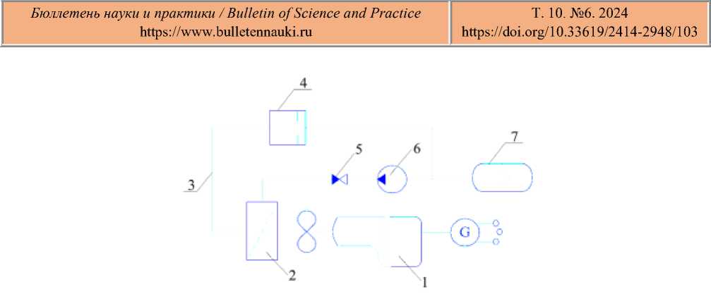
Figure 1. Experimental device for diesel generator cooling system: 1 – diesel generator; 2 – heat exchanger; 3 – pipeline; 4 – shock valve; 5 – check valve; 6 – pump; 7 – hydraulic accumulator.
In the pulse mode, the cooling of the diesel generator is improved by increasing heat transfer. The pulse mode is created by the shock valve 4 when the flow rate is higher than the set one. Then the impact valve will close abruptly and the kinetic energy of the coolant flow will be converted into potential increased pressure. Next, a wave of increased coolant pressure will go towards the heat exchanger 2 and increase its heat transfer.
When the shock valve (4) is abruptly closed, the fluid in the pipeline (3) stops moving, and the kinetic energy of the original liquid flow becomes squeezing energy, thereby increasing the pressure. Then, through the action of a pump (6), the hydraulic accumulator (7) absorbs the pulsation of flow and pressure in the system, transforming it into compressed energy or potential energy for storage. Figure 2 shows the part of the installation where heat transfer takes place.
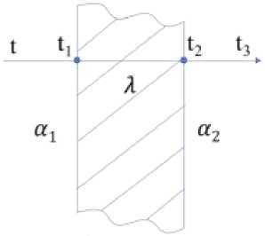
5 = 2 mm
Figure 2. Part of the heat transfer plant: t - the temperature of hot water; t 1 , t 2 - wall temperature; t 3 -the temperature of the air; α1 - convective heat transfer coefficient of water and left wall; α2 - convective heat transfer coefficient of air and right wall; δ - the thickness of the wall surface; λ - Thermal conductivity of the wall
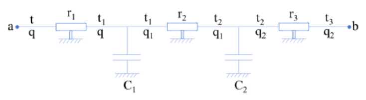
Figure 3. Heat transfer energy circuit
The circuit link equations:
(t = r1q + r2q1 + r3q2 + t3
I q = Citx + C2t2 + q2
The input and output of the energy chain for thermal calculation are presented in the form of a “black” box.
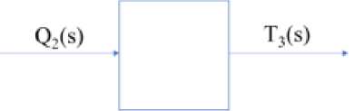
Figure 4. Black box for heat transfer
Equations for t3,t2,t2,ti,q2:
t3 = t30 + t3
t2 = r3q2 + t3
ti = r2qi + t2
q 2 = q 20 + q2
qi = C2t2 + q2
Equations on t2 from the 1st link:
t2 = r3q2 + t3 = r3(q20 + ^2) + t30 + 13 = r3q20 + r3q2 + t30 + t3
*2 = *2 = ^q2 + t3
Equations on qifrom the 1st link:
q1 = C2t2 + q2 = C2(r3q2 + £ 3 ) + q20 + q2 = C2r3q2 + C2 ^ 3 + q20 + q2
The equation on ti :
ti = r2qi + t2 = ^2^2 + C2^3 + q20 + ^2) + (Г3Ч2о + r3q2 + t30 + t3)
= C2r2r3q2 + C2rt3 + ^20 +^2+ ^20 +^2 + t30 + t3
= C2r2r3q2 + (r2 + r3)q2 + (r2 + r3)q20 + C2r2 ^ 3 + ^ 3 + £3O
The equation on ti :
ti = C2r2rq2 + (r + r3)q2 + C2T2t3 + t3
The equation on q :
q = Citi + C2t2 + q2 = Ci [ C2r2r3q 2 + (r2 + r3)q2 + C2r2^3 + £ 3 ] + C2(r3q2 + ^ + (q20 + q2 )
= CiC2r2r3q2 + (C^ + Cir3 + C2r3)q2 + q2 + q20 + CiC2r2t3 + (Ci + C2)t3
The equation on t:
t = T i q + r2q 1 + T 3 q2 + t3
= r i [c i C 2 r 2 r 3 q2 + ( C i r 2 + C i r 3 + С 2 Т 3^2 + q 2 + q 20 + C i C 2 r 2 t 3 + ( C i + C2^]
+ r2(c2r3q2 + C2 ^ 3 + q 20 + q2 ) + r3(q20 + q2 ) + t30 + ^ 3
= [^(WWh + (С 1 Г 1 Г 2 + С 1 Г 1 Г 3 + C 2 r i r 3) q 2 + r i q 2 + r i q 20 + C i C 2 r i r 2 t 2
+ (c1r1 + с 2 Г 1 )^ 3^ + ( C2r2r3q2 + С2Г2 ^ 3 + r2q20 + r2q2 ) + r3(q20 + q2 ) + t:
= C i C 2 r i r 2 r3q2 + ( C i r i r 2 + C^^ + С 2Г1Г3 + С 2 Т 2 Т3)$ 2 + (T i + r 2 + T3)q2
+ (т 1 + r2 + r3)q20 + С 1 С 2 Т 1 Т 2^3 + (с 1 Т 1 + С 2 Т 1 + С2Г2)^3 + ^ 3 + t30
—
30 + t3
Equation for images:
(a i S2 + a 2 S + a^T^s) = -(b i S2 + b 2 S + b3)Q2(s)
Coefficients:
a i = С 1 С 2 Г 1 Г 2
a 2 = C i T i + С 2 П + C 2 r 2 a3 = 1
b i = С 1 С 2 Г 1 Г 2 Г 3
b 2 = С 1Г1 Г 2 + С 1 Г 1 Г 3 + С 2 Г 1 Г 3 + С 2 Г 2 Г 3 b 3 =Т 1 +Т 2 + Г 3
Complex resistance Z (s') :
. T 3( s) -b i S2-b 2 S-b 3
Z ( S) = ТТТГ = ---FT---Г--
Q2(s) a1S2 + a2S + a3
Frequency function of the circuit:
s ^ №,j2 = -1
Frequency function of the circuit:
Z(s) =
T 3 (s)
Q2(s)
—b i S2 — b 2 S — b 3 b i Q2 — b 2 jQ — b 3
a1s2 + a2s + a3 —a1Q2 + a2jQ + a3
(b i Q2 — b 2 jQ — b 3 )[(—a i Q2 + a 3 ) — a 2 jQ]
[(—a1Q2 + a3) + a2jQ][(—a1Q2 + a 3 ) — a2jQ]
—a1b1Q4 + a3b1Q2 — a2b1jQ3 + a1b2jQ3 — a3b2jQ — a2b2Q2 +a1b3Q2 — a3b3 + a2b3jQ (—a1Q2 + a 3 )2 — a 2 j2Q2
Г —a1b1Q4 + (a1b2 — a2b1)jQ3 + (a1b3—a2b2 + a3b1)Q2 +1 (0^ 3 — a 3 b 2 )jQ — a 3 b 3
(—a i Q2 + a 3 )2 + a2Q2
We derive the real part of the complex resistance:
—a1b1Q4 + (a1b3 — a2b2 + a3b1)Q2 — a3b3 (—a i Q2 + a 3 )2 + a 2 Q2
We derive the imaginary part of the complex resistance:
, Л (а1Ь2 — а2^а3 + <^ 3 — а 3 Ь 2 ) W
m(j ) = (-а^2 + а3)2 + а2Я2
We obtain the amplitude-frequency function of the energy circuit:
(jfi) = ^Re(jfi)2 + Im(jfiy
Get the phase-frequency function of the energy circuit:
, , Im(jQ)
MW = а^‘!;;е.^-.
The known conditions:
t0 = 90oC n0 = 50W n0 50 x 103
0 = —77--= 555.56
t o 90
A = 350
F = 1m2
a 1 = 1500, a2 = 15
T i
1 a 1 F
1500 x 1
0.00067
?2
AF
2 x 10⁻³
350 x 1
= 5.71 x 10⁻⁶
7'3
1 « 2 F
15 x 1
0.0667
C i = 0.002 c2 = 0.001
Algorithm for plotting graphs.
The values of the coefficients are calculated:
а 1 = C 1 C 2 7 1 7 2 = 0.0019 x 0.0019 x 2.88 x 10-4 x 7.143 x 10-6 = 7.52 x 10⁻¹⁵
а2 = C 1 7 1 + C27 1 + C2r2
= 0.0019 x 2.88 x 10-4 + 0.0019 x 2.88 x 10-4 + 0.0019 x 7.143 x 10-6
= 1.11 x 10⁻⁶
а3 = 1
b 1 = C 1 C 2 7 1 7 2 7 3 = 0.00 1 9 x 0.00 1 9 x 2.88 x 10-4 x 7.143 x 10-6 x 3.33 x 10-2
= 2.51 x 10⁻¹⁶
b2 = С 1 Г 1 Г 2 + C1r1r3 + C2r 1 r3 + C2r2r3
= 0.0019 x 2.88 x 10-4 x 7.143 x 10-6 + 0.0019 x 2.88 x 10-4 x 3.33 x 10-2
+ 0.0019 x 2.88 x 10-4 x 3.33 x 10-2 + 0.0019 x 7.143 x 10-6 x 3.33 x 10-2 = 3.72 x 10⁻⁸
b3= 7 1 + 7 2 +7 3 = 2.88 x 10⁻⁴ + 7.143 x 10⁻⁶ + 3.33 x 10-2 = 3.36 x 10⁻²
The limit of change Q is accept, Q = 1.10 rad/s. Calculation of the real and imaginary part of the frequency function: Q = 1 rad/s.
-а1М4 + ( а^ 3 - а 2 ^ 2 + а 3 ^ 1 )^2 - а 3 Ь 3
Re{Ji2) = (-а 1 П2 + а3)2 + а2П2
Бюллетень науки и практики / Bulletin of Science and Practice Т. 10. №6. 2024
A(jQ) = jRe(jay + Im(jn)2
Im(jn-
^^-^Re^--
The dependency graph is drawn based on input values. For optimal graph perception, take only those values that affect dependencies. The obtained values for the first stage of heat transfer are shown in Table 1.
RECEIVED INFORMATION FOR HEAT TRANSFER
Table 1
|
n0, kW |
r 1 ,C2/W |
r2,C2/W |
r3,^2/W |
c 1 , W/0C2 |
C 2 ,W/C2 t0,X |
|
|
50 |
x 103 |
6.7 x 10⁻⁴ |
5.71 x 10⁻⁶ |
0.0667 |
0.002 |
0.001 90 |
|
50 |
x 103 |
13.4x10 —4 |
5.71 x 10⁻⁶ |
0.0667 |
0.002 |
0.001 90 |
|
50 |
x 103 |
20.1 x 10⁻⁴ |
5.71 x 10⁻⁶ |
0.0667 |
0.002 |
0.001 90 |
|
Table 2 VALUE AMPLITUDE FREQUENCY RESPONSE FOR ENERGY CIRCUIT |
||||||
|
Ω |
А^П) |
V i (jO- |
A2W |
^(jty |
A3W |
^ 3 (j^- |
|
1 |
0.0674 |
2.0102E-08 |
0.0680 |
7.93898E-08 |
0.0687 |
1.76718E-07 |
|
2 |
0.0674 |
4.02039E-08 |
0.0680 |
1.5878E-07 |
0.0687 |
3.53436E-07 |
|
3 |
0.0674 |
6.03059E-08 |
0.0680 |
2.38169E-07 |
0.0687 |
5.30153E-07 |
|
4 |
0.0674 |
8.04079E-08 |
0.0680 |
3.17559E-07 |
0.0687 |
7.06871E-07 |
|
5 |
0.0674 |
1.0051E-07 |
0.0680 |
3.96949E-07 |
0.0687 |
8.83589E-07 |
|
6 |
0.0674 |
1.20612E-07 |
0.0680 |
4.76339E-07 |
0.0687 |
1.06031E-06 |
|
7 |
0.0674 |
1.40714E-07 |
0.0680 |
5.55729E-07 |
0.0687 |
1.23702E-06 |
|
8 |
0.0674 |
1.60816E-07 |
0.0680 |
6.35118E-07 |
0.0687 |
1.41374E-06 |
|
9 |
0.0674 |
1.80918E-07 |
0.0680 |
7.14508E-07 |
0.0687 |
1.59046E-06 |
|
10 |
0.0674 |
2.0102E-07 |
0.0680 |
7.93898E-07 |
0.0687 |
1.76718E-06 |
A
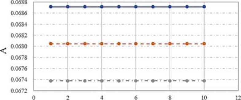
Q, rad/s
•- A IGO) -•-A20Q) —^A30Q)
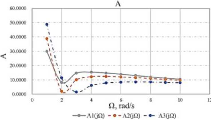
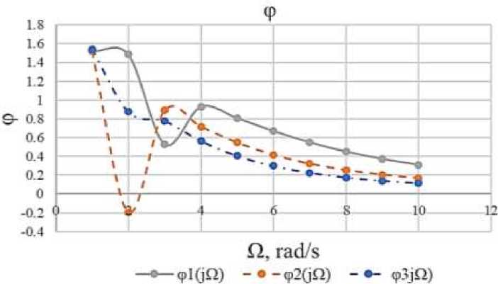
Figure 5. Amplitude frequency response
ф
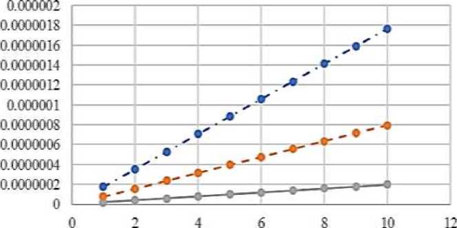
Q, rad’s
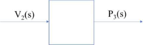
• ol(jQ) -•-o2(jQ) Figure 6. Phase frequency response In the process of modeling heat transfer in the energy circuit, it was found that the frequency increases with the increase of r1. Figure 7. Hydraulic circuit The circuit link equations: [p = r1V + mV1 + r-^2 + P3 { V = l-P + l2P3 + V2 Black box: Figure 8. Black box for hydraulic energy circuit The calculation of hydraulic circuits is similar to that of heat transfer energy circuits. The known conditions: P - pressure, kPa; V - volume flow, l/s [liter per second]; r - active resistances, [~Tt~]; m — mass of liquid, [kg]; l - hydraulic compliance, [■“—■], 1 litre = 10-3metre Parameter are calculated or found from the experiment. Are set by the input power of the circuit, for example n0 = 50 W, as well as the inlet pressure P0 = 100 kPa. Hire the pressure loss on the active resistance is assumed 5 ± 10%. V0 ^0 Po = 0.5 According to equation write the formula for r1, r2: r1 0.1 X Po Ko2 0.1 X 100 0^52 = 40 r2 = 0.5r1 = 20 The mass of water depends on the volume of pipelines. m = 10 kg The compliance is found for equation: AK P 0.5 x 0.5 0.3 X 100 = 0.0083 l2 = l1 = 0.0083 V20 = 0.2 X V0 = 0.2 X 0.5 = 0.1 Algorithm for plotting graphs. The values of the coefficients are calculated: a1 = m1l1 = 10 X 0.0083 = 0.083 a2 = 2V20l1(r1 + r2) = 2 X 0.1 X 0.0083 X (40 + 20) = 0.0996 a3 = 1 b1 = m1/1/2 = 10 X 0.0083 X 0.0083 = 0.0006889 b2 = 2V20l1l2(r1 + r2) = 2 X 0.1 X 0.0083 X 0.0083 X (40 + 20) = 0.00082668 b3 = l1 + l2 = 0.0083 + 0.0083 = 0.0166 е(/) = b2n6 + (2b1b3 + b22)n4 + b^n2 (a2b2 - a3b1 - a^jn3 + a3b3jn m(j) b2n6 + (2b1b3 + b22)n4 + b32n2 A(jn) = ^Re(jn)2 + lm(jn)2 fm(jn) ^Cn) = -^^jtr) According to equation write the formula for Table 3 CIRCUIT PARAMETERS m1,kg r1,^/m • s r2,^/m • s 11, lit • s/kPa l2, lit • s/kPa P30,kPa V20, lit/s 10 40 20 0.0083 0.0083 100 0.1 20 40 20 0.0083 0.0083 100 0.1 30 40 20 0.0083 0.0083 100 0.1 Dependency graphs are plotted based on the input values. For the best perception of graphs values are taken only those that affect the dependence. The values obtained for the first stage of the energy circuit are shown in Table 4. RECEIVED INFORMATION FOR HYDRAULIC Figure 9. Amplitude frequency response Figure 10. Phase frequency response Table 4 Q Ai(jQ) Pi(jQ) A2(jO) 2(jO) A3(jQ) Рз№) 1 48.8531 1.5182 38.7890 1.5232 30.0373 1.5410 2 11.5191 1.4857 2.0795 -0.1948 8.2592 0.8745 3 1.5798 0.5296 10.0460 0.8912 14.7013 0.7758 4 6.1112 0.9286 12.1857 0.7176 15.3358 0.5643 5 7.8720 0.8072 12.3997 0.5477 14.7742 0.4056 6 8.4598 0.6705 12.0570 0.4174 13.8976 0.2984 7 8.5769 0.5501 11.5156 0.3230 12.9453 0.2263 8 8.4839 0.4516 10.9020 0.2552 12.0150 0.1766 9 8.2842 0.3736 10.2770 0.2057 11.1489 0.1412 10 8.0269 0.3121 9.6720 0.1689 10.3614 0.1153 Based on the results of the calculation, the graphs of the amplitude frequency response and phase-frequency response and frequency response of the circuit are constructed. Further in these graphs are under construction. In the process of modeling the hydraulic power circuit, it was found that as the mass increases, the frequency of the hydraulic circuit quickly reaches its minimum value, oscillates, and ultimately the frequency decreases as the mass increases. With an increase in the mass of water in the circuit, the amplitude decreases at low frequencies (less than 4 rad/s) at frequencies close to 10 rad/s, the amplitudes are aligned. The best frequency will be 3-4 rad/s for 1 parameter variant.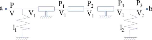
References The power circuit of mechanical damping device for cooling system of 50 kW pulse diesel generator
- Yin, C., Wu, H., Locment, F., & Sechilariu, M. (2017). Energy management of DC microgrid based on photovoltaic combined with diesel generator and supercapacitor. Energy conversion and management, 132, 14-27. https://doi.org/10.1016/j.enconman.2016.11.018
- Song Jianhua. (2021). Research on the Application and Technological Development of Diesel Generator Sets. Wen Yuan (High School Edition), (6), 3455.
- Wang, Z., Shuai, S., Li, Z., & Yu, W. (2021). A review of energy loss reduction technologies for internal combustion engines to improve brake thermal efficiency. Energies, 14(20), 6656. https://doi.org/10.3390/en14206656
- You, W., Wu, L. H., Yuan, Y. N., & Xi, G. N. (2015). Smart Grid Control Technology of Multi Diesel Generator Set. Advanced Materials Research, 1070, 1322-1325. https://doi.org/10.4028/www.scientific.net/AMR.1070-1072.1322
- Li, Yuanyuan. (2021). Discussion on Reliability Evaluation Methods for Insulation Systems of Wind Turbines. Motor and Control Applications, (8), 90-97.
- Vei, Tszyuan', & Chzhan, Tszyan'go, i Tsyu Tao (2020). Neveroyatnostnyi analiz nadezhnosti rotora generatora na osnove termicheskogo analiza.41(12), 3099-3105. (in Chinese).
- Ma, Khuaiten, Din, Yuisyan & Cheng, Baomin (2016). Raschet i analiz ventilyatsii I teploperedachi v zvukoizolyatsionnom kozhukhe opredelennogo tipa morskoi dizel'-generatornoi ustanovki na osnove CFD.38(5), 24-27. (in Chinese).
- Xu, Naiqiang, & Tian, Zhihui, et al. (2017). Design of a set of water-cooled components for a closed box silent diesel generator set. Mechanical and Electrical Engineering Technology, (11), 39-43.
- Li Jingjing. (2013). Noise and Thermal Analysis of Small and Medium Power Diesel Generator Sets. University of Electronic Science and Technology, 4-6.
- Wu, Y., Guo, J. Z., Hu, L., & Luo, R. (2016). Simulation and test research for the multistructure of automotive louvered fins heat exchangers. Science Technology and Engineering, 16(11), 59-64.
- Tong, Zhengming, Yang, Qiuxiang, & Yin, Yuan. (2016). A new method for simulating the air outlet temperature of a car radiator. Chinese Internal Combustion Engine Engineering, (4), 181-186.
- Wang, Yi, Shangguan, Wenlong, & Liu, Xiaoang. (2015). Design methods of the mounting system for condenser-radiator-fan module in a vehicle. Automotive Engineering, (2), 155-159.
- Zhang, Bingkun, Zhao, Jin, & Mi, Youjiang. (2017). Optimization design and simulation of the radiator matching of the engine cooling system. Computer Simulation, (5), 37-42.
- Li Jun, Zeng Zhiping, Zhang Shiyi. (2015). Influence of waveforms on wavy fin radiator heat dissipation capability and resistance performance. Machinery Design & Manufacture, (10), 76-79.
- Zhang, Bingkun, Zhao, Jin, & Mi, Youjiang (2017). Optimization design and simulation of the radiator matching of the engine cooling system. Computer Simulation, (5), 37-42.
