The pressure loss and the filtration coefficients in pipelines with grids

Author: Loktionova Elena, Polupanova Julie, Latukhina Anastasia
Journal: Строительство уникальных зданий и сооружений @unistroy
Article in issue: 11 (62), 2017.
Free access
A variety of grids and lattices that occur in different spheres of practical activity requires detailed study. The presence of these devices leads to additional resistance and energy losses during their flow. The paper discusses a flat plastic perforated mesh with different degree of permeability at the outlet of the pipeline. The coefficients of grid resistance were determined experimentally. The effect of grids on the total head loss were established through the presence of resistance coefficients volume method at fixed pressure: we determined the flow at the exit of the horizontal pipe of constant cross section, the end of which was mounted the investigated grid. To precise definition, the obtained values along with the experiments on the measurement of costs used a method of determination using piezometers: according to the length of the flow part were installed piezometers and the values of the coefficients of resistance were established on the basis of differential pressure. The identity of the two methods of determining the resistance coefficients is shown, in terms of flow rate and pressure drop on the grids. The effect of grids on the capacity of the pressure pipeline has been established: the replacement of the flow part does not affect to the numerical values of resistance coefficients of the grids. The dependence of the relative flow rate in the pipe on the surface porosity of the grids is obtained; this dependence gives a qualitative estimate of the reduction in the capacity of the pipe in the installation of meshes. The experimental data for constructing this dependence agree with the calculations for the approximating dependence established earlier. The transition from resistance coefficients to filtration coefficients and permeability of the pipeline with grids is suggested, because it is more convenient in practical calculations by characteristics. Graphs of the permeability coefficients dependence, related to the pipe cross-section area, and the filtration coefficients on the surface porosity of the grids are given. The proposed dependencies are linear functions of the surface porosity.
Perforated grids, discharge coefficient, resistance coefficient, exposed porosity, filtration coefficient, permeability coefficient
Short address: https://sciup.org/143163567
IDR: 143163567 | DOI: 10.18720/CUBS.62.5
Потери давления и коэффициенты фильтрации в трубопроводах с сетками
Многообразие сеток и решеток, встречающихся в разных сферах практической деятельности, требует их детального исследования. Наличие этих устройств приводит к дополнительным сопротивлениям и потерям энергии при их обтекании. В работе рассмотрены плоские пластиковые перфорированные сетки разной степени проницаемости на выходе из трубопровода. Экспериментально определены коэффициенты сопротивления сеток. Влияние сеток на общие потери напора устанавливалось через нахождение коэффициентов сопротивления объемным способом: при фиксированных напорах определялся расход на выходе из горизонтального трубопровода постоянного сечения, в конце которого устанавливались исследуемые сетки. Для уточнения полученных значений наряду с опытами по определению расходов использовался способ измерения с помощью пьезометров: по длине проточной части устанавливались пьезометры и значения коэффициентов сопротивления устанавливались исходя из перепада давления. Показана тождественность двух способов определения коэффициентов сопротивления - по расходу и по перепаду давления на сетках. Установлено влияние сеток на пропускную способность напорного трубопровода: замена проточной части не влияет на численные значения коэффициентов сопротивления сеток. Получена зависимость относительного расхода в трубе от поверхностной пористости сеток, эта зависимость дает качественную оценку снижения пропускной способности трубы при установке сеток. Опытные данные для построения этой зависимости согласуются с расчетами по аппроксимирующей зависимости, установленной ранее. Предложен переход от коэффициентов сопротивления к коэффициентам фильтрации и проницаемости трубопровода с сетками, так как последние являются более удобными в практических расчетах характеристиками. Приводятся графики зависимости коэффициентов проницаемости, отнесенных к площади сечения трубы, и коэффициентов фильтрации от поверхностной пористости сеток. Предложенные зависимости являются линейными функциями от поверхностной пористости.
Text of the scientific article The pressure loss and the filtration coefficients in pipelines with grids
Grids and lattices in liquid or gas streams are found in pipelines and other elements of systems and structures in water supply, construction, ecology, engineering, metallurgy and other fields. The choice of the type and design of the grid is determined by its purpose and operating conditions. In this case, grids differ in material, configuration, geometry of cells and technology of their manufacture [1-3].
The main task in the calculation of systems and structures equipped with grids is to determine the resistance coefficients of these devices and to estimate their contribution to total head losses [4-12]. The value of the hydrodynamic resistance is of great importance in the design and construction of a various hydraulic structures, power plants (turbine, compressor, pumping), apparatus and manifolds for various purposes. Grids are installed to regulate the turbulent flow in the pipes (in order to suppress or increase the turbulence of the liquid or gas in the flow). It is their hydrodynamic resistance that determines the flow regime passing through such a hydro-irrigation device. The formation of vortex regions, velocity drops and the energy of a moving stream are also related to the resistance coefficient [13].
The flow pattern of a liquid or gas through a grid is extremely complex and is determined by many factors, so an accurate hydromechanical estimate of head losses and calculation of the resistance coefficients is impossible. Their values are established, as a rule, by experience [14-18]. The dependence of the resistance coefficients of grids and lattices on geometric features and flow conditions was studied, for example, in [19-28]. As the review of the literature shows for some practical problems by different authors, independently of each other, obtained results give good agreement in these experiments and in calculations on the recommended empirical dependences [16, 17, 29]. Recommendations were developed on the choice of optimal formulas for the calculation of hydraulic resistances, for the choice of structures and geometric characteristics [14, 15]. On the contrary, no information on the systematic study of the resistance coefficients of perforated nets and grids has been found in the literature [11]. Resistance was studied depending on the Reynolds number, on the filling of the gratings, and on the ratio of the relative thickness of the gratings to the diameter of the holes. The authors concluded that the coefficient of resistance of perforated nets is higher than that of two-plane and braided grids, and empirical dependence is recommended.
From the analysis of the literature it follows that the question of the resistance of lattices and grids is at the moment no less relevant than several decades ago [11, 12]. This is due not only to the emergence of new practical tasks, but also with the use of new materials and the introduction of modern technologies in production. In this case, the contribution of each new factor to the total resistance of the grid can be established by special experimental studies.
In this paper, we discuss the results of hydraulic tests of perforated plastic grids installed at the end of the water pressure main with a free flow out of it. The experiments are the continuation of the experiments, the results of which are discussed in [30]. The studies were carried out on an expanded range of grids of different degrees of perforation with the replacement of the flowing part of the water conduit at the same ratio of length to diameter ( l / D = 20 ).
The aims of the work is to clarify the dependencies, compare with the values obtained in the studies [30], test another method for determining the coefficient of resistance and matching of the results.
To achieve these aims, it need to decide the following objective:
- determination resistance coefficients of the grid on the basis of measuring the flow and comparing them with the values found in the experiments [30];
- determination dependence of the relative flow rate in the pipe line with the grids on their surface porosity and comparison of the results with the approximation line proposed in [30];
- determination resistance coefficients of the grids by differential pressure on the corresponding devices and comparison their values with the series data of experiments on the flow;
- establishment a connection between pressure losses and filtration flow characteristics by introducing permeability coefficients of nets.
2. Methods
The first series of experiments on the measurement procedure coincided with the system adopted in [28], where the flow rate at the outlet from a horizontal pipeline of constant cross section was determined by a volumetric method at the fixed heads, at the end of which the investigated grids were installed (Fig. 1). At the same time, the flowing part of the water conduit, used in [28], was replaced, with the ratio of length to diameter remaining.
In order to refine the Z c values, in addition to the experiments on measuring costs, another method for determining the resistance coefficients was also used, for example, in [1, 4-6,16]. Piezometers were installed along the length of the flow-through part. Measuring the pressure drop directly on the grid, the values of the resistance coefficients were calculated from the formula
Construction of Unique Buildings and Structures, 2017, №11 (62)
z
pY = РP vo/2 g v0
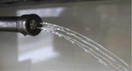
Figure 1. Grid samples and flow pattern
where p - excess pressure in front of the grid, - average speed in the pipeline. The data of this series of experiments are plotted in Fig. 4.
e»®®ooooo
3. Results and Discussion
Plotting the graph (Fig. 2) based on the results of the 1 range experiments, which shows the dependence
« of the tensile resistance coefficients Zc on their surface porosity nto = —— ( «п - is the total area of the grid «о holes (lumen area), №q- is the cross-sectional area of the tube). On the graph, the markers indicate the experimental points, and the data obtained in the experiments of [28] are represented in the form of an approximation line.
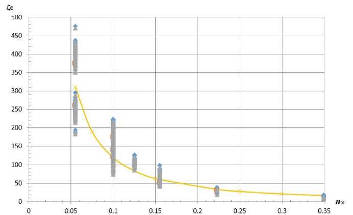
Figure 2. The plot of Z c f ( n ® )
(a series of experiments on the flow rate in the pipe)
(markers are experimental points on a new water conduit, continuous thick line- approximation of experimental values on an old water conduit [28]).
As can be seen from Fig. 2, the experimental values of the resistance coefficients of the current obtained in the conditions of the new flow part are well approximated by the dependence
Zc = 3( (1Ю1-6-1)
proposed in [27]. Thus, it can be argued that the numerical values of the resistance coefficients depend only on the geometric features of the mesh (surface porosity, the number of holes, their mutual arrangement, etc.) and are not characteristics of the inner surface of the flowing part. The spread of the experimental points in Fig. 2 for the same surface porosity shows the influence of the number of holes and their mutual arrangement within the cross-section of the grid (at n«= const several grids were investigated).
Construction of Unique Buildings and Structures, 2017, №11 (62)
In the graph of Fig. 3 shows the dependence of the relative flow rate in the pipe with the grids on their surface porosity
Q c / Q о = f( n „ ),
Where Q c - the flow rate in the pipe in the presence of a grid, Q q - the flow rate in a pipe without a grid, previously established experimentally according to the method described above, with the same head at the center of the outlet cross-section of the pipe as Q c . The solid line is constructed taking into account the approximation
(1), i.e.
Q с №0= ~ Mo
1+ Co
1+ Zo
V + Zo + Zc
V + Zo + 3( (1/n®)1 '6 -1)
Where Цс and Цо - the coefficients of flow of the pipeline in the presence of a grid and without it, respectively, Zq- the experimental coefficient of resistance of the pipe without a grid.
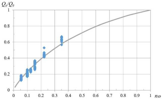
Figure 3. Dependency graph Q c ' Q 0 =f( n ® ),
Fig. 3 demonstrates a qualitative assessment of the reduction in pipe capacity when using devices (nets) of a particular configuration. For example, from Fig. 3 it can be seen that the installation of a grid with a surface
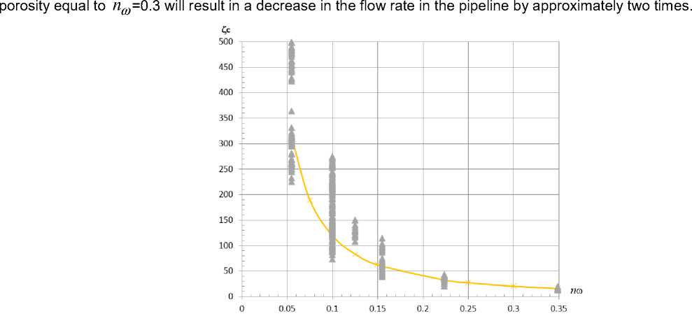
Figure 4. Dependency graph Z c f ( n ® )
(A series of experiments on pressure drop on grids)
Construction of Unique Buildings and Structures, 2017, №11 (62)
Comparison of Fig. 2 and 4 shows that the resistance coefficients found from the flow and from the differential pressure coincide with an acceptable sin. In such circumstances, it is not recommended to use to establish a reliable confidence interval of measurements of the density distribution Gaussian. A similar situation is observed in [5], which carried out a systematic study of perforated grids, and to reduce the scatter of experimental points in the presentation of the results of the measurements were used the methods of similarity theory. The noticeable scatter of the points were in the work [33].
Based on the measurement data, it is possible to represent the fluid flow in a pipeline whose hydraulic characteristics are determined mainly by the presence of a grid at the outlet of it (or in its other part) as a filtration flow. Then the average velocity in the tube will be interpreted as the filtration rate, determined by the relation vo = k^J (4)
where - the coefficient of filtration, - the hydraulic gradient.
Equation (4) is the law of turbulent filtration [31, 32].
Since for is also true
vo = Ac • V2g • H = 1 1 „ • 72g • H V1+Zo + Zc
where Н is the head over the center of the outlet section of the pipeline, then, equating (4) and (5), we obtain
M c • V2 gH = k^J или k = M • JgH (6)
pγ
( 3 - the thickness of the grid) leads to the
The substitution in (6) of the hydraulic gradient J =—— о expression for
|
k = M c ^ |
2 g • H-5 = p γ |
2 g ■ H 5 _ (1 + Z o+ Z c)• p/Y |
2 g ° • (1 + Z o + Z c ) \ |
— = С • p γ |
H p γ |
\ Mc
where С = --2g °-- \ (1+Z0 + Zc )
- a constant value for a pipe with a fixed mesh, which has a speed
dimension.
Fig. 5 represents the relationship between the filtration coefficients and the surface porosity of the grids in accordance with (7), where the coefficient Z c is determined by formula (1).
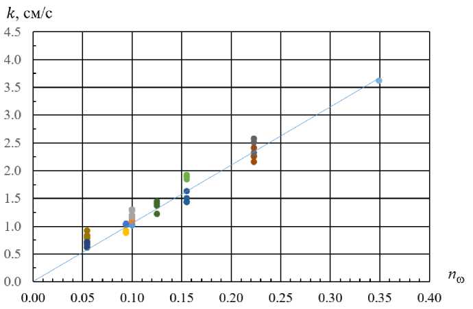
Figure 5. Graph of the dependence of the filtration coefficients
from the surface porosity of the nets k f ( n to )
According to the definition in the theory of filtration [31, 32] if we introduce into the calculated dependence
V
-
(7) instead of the filtration coefficient k the coefficient of permeability of the grid k 0 = k — , where v is the g
kinematic coefficient of viscosity of the liquid, the resulting complex will have the area dimension. In this case, k 0 is the value of the cross-sectional area of the channels of the porous medium, i.e. The area through which the actual filtration takes place (in our case, the area of the grid holes). Thus, the permeability coefficient can be interpreted as a measure of the filtration conductivity of a pipeline with a grid.
In Fig. 6 is a graph of the permeability coefficients related to the cross-sectional area of the pipe from the surface porosity of the grid.
Comparing Fig. 2 and 6 (or 4 and 6), it is easy to see that when changing from the resistance coefficients Z c to the permeability coefficients of the grids k q , the proposed dependence (1) becomes a linear function of the surface porosity, where k ' = ( k 0 / ^ 0 ) -10-5 ~2- n ^ is the dimensionless coefficient.
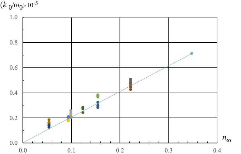
Figure 6. Graph of dependence of permeability coefficients from the surface porosity of the nets k0/ to 0 f ( n ® )
Coefficient 2 is approximate, and the values of k ' for the same n m depend on the number of grid apertures and their relative position along the cross-section, but the scatter of the points in Fig. 6 for a fixed porosity is much smaller than in Fig. 2 (or 4). Thus, the parameter k 0 can be considered more convenient and universal characteristic of a perforated grid.
In this paper following results have been received:
1. Replacement of the flow part does not affect the numerical values of the grid resistance coefficients in comparison with [28].
2. Dependence of the relative flow rate on the surface porosity in the tube with the mesh gives a qualitative estimate of the reduction in the throughput capacity of the pipe when installing grids. Experimental data for constructing this dependence agrees with the approximation proposed in [28].
3. Determination of the coefficients of resistance of the nets by the flow rate and by the pressure drop are equivalent.
4. The coefficient of permeability is a measure of the filtration conductivity of a tube with a grid and is more convenient in practical calculations than in comparison with the coefficients of resistance.
4. Conclusions
Construction of Unique Buildings and Structures, 2017, №11 (62)
The installation of perforated grids and lattices leads to additional head losses, so an important task is to determine the values of the resistance coefficients, and two methods can be used: depending on the flow rate and the pressure drop.
The use of grids significantly reduces the capacity of such pipelines, a qualitative assessment of this will help the dependence of the relative flow rate on surface porosity.
In some cases it is more convenient to use the permeability coefficient as a measure of the filtration of a pipeline with a grid than the coefficient of resistance.
References The pressure loss and the filtration coefficients in pipelines with grids
- Idel'chik I.E. Spravochnik po gidravlicheskim soprotivlenijam . Moskow: Mashinostroenie, 1992. 672 p. (rus)
- Idelʹchik I.E. Handbook of hydraulic resistance 4th ed. rev. and augment-ed. Begell House in Redding, CT. United States, 2008. 881 p.
- Al'tshul' A.D. Gidravlicheskie soprotivleniya . Moscow: Nedra, 1982. 224 p. (rus)
- Al'tshul' A.D., Kalicun V.I., Majranovskij F.G., Pal'gunov P.P. Primery raschetov po gidravlike . Moscow: Strojizdat. 1976. 256 p. (rus)
- Idel'chik I. E. Uchet vliyaniya vyazkosti na gidravlicheskoe soprotivlenie diafragm i reshetok . Teploehnergetika. 1960. No. 9. Pp. 75-80. (rus)
- Yu.J., Xin.B., Shen.C., Liu.Y. Preparation and characterization of anti-mosquito polyester nets finished by bendiocarb/alphacypermethrin. Journal of the Textile Institute. 2016. No. 11(107). Pp. 1369-1374.
- Datcenko E.N., Vasil'ev N.I., Avakimjan N.N., Savenok O.V., Koshelev A.T. Gidravlicheskoe soprotivlenie techeniju zhidkosti cherez poristuju sredu // Stroitel'stvo neftjanyh i gazovyh skvazhin na sushe i na more, 2014. - № 12. - Pp. 18-20. (rus)
- Kaljakin A.M., Chesnokova E.V. Novaja zavisimost' dlja opredelenija kojefficienta gidravlicheskogo soprotivlenija v perehodnoj zon soprotivlenija (ot laminarnogo k turbulentnomu) . Magazine of Civil Engineering. 2012. No. 2. Pp. 51-55. (rus)
- Al'tshul' A.D., Kalicun V.I. Gidravlicheskoe soprotivlenie truboprovodov . Moscow: Strojizdat. 1975. 285 p. (rus)
- Baines W.D., Peterson E.G. An investigation of flow through screens. Transactions of the ASME. 1951. No. 5(73). Pp. 467-480.
- Derbunovich G.I., Zemskaja A.S., Repik E.U., Sosedko Ju.P. Gidravlicheskoe soprotivlenie perforirovannyh reshetok . Uchenye zapiski TsAGI. 1984. No. 2. Pp. 114-118. (rus)
- Velikanov N.L., Korjagin S.I., Naumov V.A. Gidrodinamicheskoe soprotivlenie reshetok i setok v prjamom truboprovode . Vestnik mashinostroenija. 2014. No. 6. Pp. 44-47. (rus)
- Taganov G.I. Vyravnivayushchee dejstvie setok v potokah zhidkostej i gazov . Trudy CAGI. 1947. No. 604. Pp. 14. (rus)
- Derbunovich G.I., Zemskaja A.S., Repik E.U., Sosedko Ju.P. K voprosu o gidravlicheskom soprotivlenii setok . Uchenye zapiski TsAGI. 1980. No. 2. Pp. 133-136. (rus)
- Velikanov N.L., Naumov V.A., Primak L.V. Gidrodinamicheskoe soprotivlenie setok . Mehanizacija stroitel'stva. 2014. No. 11(845). Pp. 28-31. (rus)
- Povkh I. L. Aerodinamicheskii eksperiment v mashinostroenii . Leningrad: Mashinostroenie. 1974. 479 p. (rus)
- Schlichting H. Ergebnisse und Probleme von Gitteruntersuchungen. ZFW. 1953. No. 1. Pp. 109-122
- Hanzhonkov V.I. Soprotivlenie setok . Promyshlennaja ajerodinamika. 1944. No. 3. Pp. 210-214. (rus)
- Loehrke R.I., Nagib H.M. Experiments on management of free-stream turbulence. 1972. AGARD Rep. № 598.Chicago, 1972. 100 p.
- Tan-Atichat J., Nagib H.M., Loehrke R.I. Interaction of free-stream turbulence with screens and grids: a balance between turbulence scales. J. Fluid Mech. 1982. No. 114. Pp. 501-528.
- Paschen M. Contributions on the theory of fishing gears and related marine systems. Proceeding of the 8-th International Workshop on Methods for the development and evaluation of maritime technologies. 2007. No. 5. Pp. 23-34.
- Song D.H. Experimental investigation on the hydrodynamic coefficients of netting. Proceeding of the 9-th International Workshop on Methods for the development and evaluation of maritime technologies. 2009. No. 9. Pp. 77-94.
- Madsen N. Experimental analysis of the hydrodynamic coefficients of the net panels in the flume tank in hirtshals. Proceeding of the 10-th International Workshop on Methods for the development and evaluation of maritime technologies. 2011. No. 10. Pp. 131-140.
- Altshul A. D. Kiselev P. G. Gidravlika i aerodinamika . Moscow: Gosstroiizdat. 1975. 323 p. (rus)
- Bredov V.I. Ob opredelenii velichiny mestnyh gidravlicheskih soprotivlenij v truboprovodah. Gidravlika odnorodnyh i neodnorodnyh zhidkostej . MISI.1972. No. 89. Pp. 44-51. (rus)
- Pil'gunov V.N., Efremova K.D. Verifikacii matematicheskih modelej tipovyh mestnyh gidravlicheskih soprotivlenij . Inzhenernyj vestnik. 2013. No. 11. Pp. 29-56. (rus)
- Chemezov D. The character of the fluid flow in the pipelines with the local hydraulic resistances. ISJ Theoretical & Applied Science. 2016. No. 12 (44). Pp. 62-68.
- Kurganov A. M. Fedorov N. F. Spravochnik po gidravlicheskim raschetam sistem vodosnabzheniia i kanalizatsii . Leningrad: Stroiizdat. 1973. 408 p. (rus)
- Repik E.U., Sosedko Ju.P. Razrabotka deturbulizirujushhih setok s malym gidravlicheskim soprotivleniem dlja ajerodinamicheskih trub . Uchenye zapiski TsAGI. 2011. No. 3(42). Pp. 84-91. (rus)
- Latuhina A.I., Loktionova E.A., Polupanova Ju.R. Gidrodinamicheskoe soprotivlenie setok v napornyh vodovodah . St. Petersburg State Polytechnical University Journal. 2016. No. 2(243). Pp. 174-180. (rus)
- Brjanskaja Ju.V. Utochnenie kinematicheskih harakteristik turbulentnogo techenija . Magazine of Civil Engineering. 2013. No. 6. Pp. 31-38. (rus)
- Muskat M. The flow of homogeneous fluid through porous media. Michigan: J.W. Edwards Inc. 1946. 753 p.
- Polubarinova-Kochina P.Ja. Teorija dvizhenija gruntovyh vod . Moskow; Nauka. Glavnaja redakcija fiziko-matematicheskoj literatury. 1977. 664 p. (rus)
