The Registration of Knee Joint Images with Preprocessing

Author: Zhenyan Ji, Hao Wei
Journal: International Journal of Image, Graphics and Signal Processing(IJIGSP) @ijigsp
Article in issue: 4 vol.3, 2011.
Free access
The registration of CT and MR images is important to analyze the effect of PCL and ACL deficiency on knee joint. Because CT and MR images have different limitations, we need register CT and MR images of knee joint and then build a model to do an analysis of the stress distribution on knee joint. In our project, we adopt image registration based on mutual information. In the knee joint images, the information about adipose, muscle and other soft tissue affects the registration accuracy. To eliminate the interference, we propose a combined preprocessing solution BEBDO, which consists of five steps, image blurring, image enhancement, image blurring, image edge detection and image outline preprocessing. We also designed the algorithm of image outline preprocessing. At the end of the paper, an experiment is done to compare the image registration results without the preprocessing and with the preprocessing. The results prove that the preprocessing can improve the image registration accuracy.
Image registration, preprocessing, knee join, CT, MR
Short address: https://sciup.org/15012147
IDR: 15012147
Text of the scientific article The Registration of Knee Joint Images with Preprocessing
Published Online June 2011 in MECS
To analyze the effect of PCL (posterior cruciate ligament) and ACL (anterior cruciate ligament) deficiency on knee joint, it’s necessary to build a 3D model of human knee joint. CT and MR images have different limitations. CT images can outline bone very accurately but provide less detailed information in the soft tissues. MR can provide higher detail in the soft tissues but less detail about bony structures. If we can fuse them together via image registration, we will get a model with detailed information in both the soft tissues and the bony structures.
Two most used solutions in image registration are feature points detection and mutual information. Mutual information was firstly applied to image registration by Viola etc.[1]. Based on Viola’s work, Likar etc. [2] also proposed a mutual information-based elastic registration. This registration method subdivides image into many small parts, and locally registers every subimage, then interpolates between registered sub-images.
Josien etc. firstly proposed an extended registration method based on mutual information and image gradient information. Comparing with general mutual information
Sponsored by National Natural Science Foundation of China, project No.50975013
registration, the extended image registration could improve the registration results because image gradient information contains rich spatial information and can help to make registration images align better. The results are tested on each pair of CT, PET and MR [3]. Chen etc.[4] applied the maximum mutual information and gradient information to non-rigid image registration and optimized the registration method with some algorithms such as Powell search algorithm, gray interpolation, etc.
Mellor and others [5] firstly found the connection between the features of two medical images. They proposed a registration method, phase mutual information, based on image feature rather than the relationship between intensity of two images. And the method of phase mutual information is significantly more robust than an intensity method to images that corrupt the common intensity mapping.
Because image registration based on mutual information is robust and has higher sub-pixel precision, we use image registration based on mutual information in our project.
However, MI registration was mainly used in the registration of brain images. The knee joint images have different characteristics comparing with brain images. Firstly, the match of bones is most concerned in the registration of knee joint images. Secondly, the interference that affects accuracy of result most is cortex fat and muscle of patient because MI registration is data-independent and it will calculate both data of bones and human soft tissues. In the images of knee joint, there is much information about adipose, muscle and other soft tissues and the information will affect the registration accuracy. Comparing with knee images, brain images' cortex is thin enough to be ignored and the edge of a brain in images is also the edge of skeleton. With brain images, the result of MI image registration is of high quality. But in the images of knee joint, the redundant information such as adipose, muscle and other soft tissue affects the accuracy of registration greatly. To improve the accuracy of registration, we need introduce image preprocessing to reduce interference information in the images.
We proposed a combined preprocessing solution, BEBDO. In BEBDO preprocessing solution, first image blurring is done to effectively smooth local noises.
Secondly, image enhancement is done to increase contrast of images. Thirdly, image blurring is done again to further reduce interference. Fourthly, image edge detection is done to extract the bone edges. In the end, image outlines processing is done to remove the outlines of the leg.
After the preprocessing is finished, the preprocessed images are used to get the floating image’s movement parameters based on Powell Method and Mutual Information. Then the movement parameters are used to adjust the original CT images and then fuse with the MR images.
With the result, we can prove that the registration accuracy is improved with the combined preprocessing.
Here we introduce our combined preprocessing solution BEBDO and registration solution step by step.
interference information should be removed, otherwise they will affect the precision of registration.
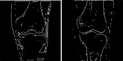
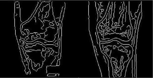
Figure 2 the edge detection without preprocessing
(a) The edge detection on original MR image
(b) The edge detection on original CT image
-
II. Image preprocessing
To reduce interference from cortex, fat and muscle, we need do preprocessing on knee images. Our image preprocessing solution as Fig.1 consists of five steps, image blurring, image enhancement, image blurring, image edge detection, and outline processing. The image blurring is performed twice, before and behind image enhancement.
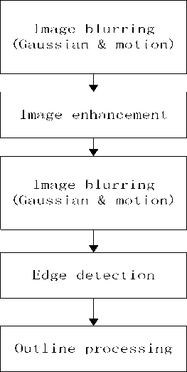
Figure 1 flow chart of image preprocessing
-
A. Image Blurring
Image blurring is important to register the MR and CT images of knee joint. If we directly do image enhancement and image detection on images without image blurring, the results see Fig.2. In the result images, much interference information, such as noise points from soft tissues and outlines from boundaries of adjacent large area soft tissues left besides bone outlines. These
To remove the interference information in the images, we adopt image blurring.
We separately use Gaussian blurring and motion blurring to preprocess the images, and find that Gaussian blurring is good at eliminating small sized noise points and motion blurring can smooth boundaries between soft tissues better. The results see Fig. 3. For MR images, the image Fig. 3(a) after Gaussian blurring has less noise points than Fig. 3(b), the one after motion blurring. For CT images, the image Fig. 3(c) after Gaussian blurring has more outlines of soft tissues
(a)
(b)
(c) (d)
Figure 3 Images after blurring
(a)MR image with Gaussian blurring
(b)MR image with motion blurring
(c)CT image with Gaussian blurring
(d)CT image with motion blurring than Fig. 3(d), the one after motion blurring. Gaussian blurring and motion blurring have different advantages. To achieve better blurring effect, we combine Gaussian blurring and motion blurring together.
First, we use Gauss distribution function to filter the images. The Gauss distribution function[5] is described as
G(x, y) =
2 П *
( 1 )
The Gaussian blurring can partly get rid of the soft tissue details that may become noise points after edge
(a)
(b)
(c) (d)
Figure 4 The results after image blurring
-
(a) The MR image after Gaussian blurring and motion blurring
-
(b) The original MR image
-
(c) The CT image after Gaussian blurring and motion blurring
-
(d) The original CT image
detection. However, it should be cautious to choose parameters of Gaussian blurring. Because image blurring can blur not only soft tissues but also bones, the information of bones will also have a loss if the parameters were too large. In MATLAB 7.10, we use fspecial('gaussian',hsize,sigma) to create Gaussian blurring filter. After some experiments, we choose hsize = [2 2] and sigma = 0.7 for MR images. CT images are different from MR images. They have clear contrast of bone and do not have much interference data from soft tissues as MR image, since CT imaging is not sensitive to low density tissues like adipose. So in the image blurring algorithm parameters should be smaller than ones applied to MR image. We select hsize= [2 2] and sigma=0.3 for CT images.
After Gaussian blurring, motion blurring is adopted to blur visible outlines of soft tissue boundaries. Then in edge detection, most of outlines from the boundaries of soft tissues will be removed. The parameters of motion blurring we choose should be large enough to basically remove outlines we mentioned before. In MATLAB 7.10, we use fspecial('motion',len,theta) to create motion blur filter. After many experiments, we select len = 3 and theta = 10 for MR images, and select len=2 and theta=10 for CT images.
The results are illustrated as Fig.4.
-
B. Image Enhancement
After blurring, the images need to be enhanced so that the gray value information of bones is not wakened too much. This step can also increase the accuracy of image edge detection. We adopted Laplacian filter to make images have more contrast. The algorithm of enhancement[5] with the Laplacian is defined as g (x, y) = f (x, y) + c[V2 f (x, y)] (2)
The g(x, y) is the enhanced image, f(x, y) is the original image, V f ( x , y ) is the Laplacian of the image, and c is 1 or -1 depending on the coefficient of spatial mask of Laplacian.
After this step, the bones and the soft tissues show a high contrast in the image (see Fig. 5).
(a) (b)
Figure 5 Images after enhancement
-
(a) MR image after enhancement
-
(b) CT image after enhancement
-
C. Image Blurring
After image enhancement, not only the bones’ information but also interference is strengthened. Gaussian blurring and motion blurring are applied to images again to further reduce the interference. Considering bones information has better contrast now, image blurring this time can use larger parameters. So for Gaussian blurring we choose hsize = [4 4] and sigma = 2 to process enhanced MR images. In motion blurring, the parameters are selected as the same as the first time, i.e. len = 3 and theta = 10.
For enhanced CT images, the parameters of Gaussian blurring are hsize= [2 2], sigma=0.6, and parameters of motion blurring are len=2, theta=10.
The results see Fig. 6.
(a)
(b)
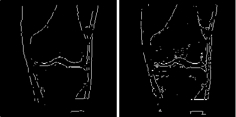
Figure 6 Images after the second blurring
(a)
(b)
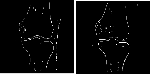
Figure 7 Images after Canny edge detection
(a) MR image after edge detection based on Canny algorithm
(b) CT image after edge detection based on Canny algorithm
-
(a) MR image after the second image blurring
-
(b) CT image after the second image blurring
-
D. Image Edge Detection
In this step, data of the bone edges and a little soft tissue edges is extracted via image detection method.
The detection of Edge uses the derivative to determine whether there is mutation in the gray value of pixels in the image. The gray values of pixel set around the domain of image edge are usually not continuous and have obvious episodic changes. Therefore, we can get edge information via the first or the second derivative.
Edge detection techniques can generally be classified into two categories: gradient based edge detection and Laplacian based edge detection. Gradient based edge detection uses the first derivative to detect image edge. Laplacian based edge detection uses the second derivative and is usually more accurate and more complex than gradient detection [6].
The pixel modulus G(x, y) can be calculated as
= V ( f ( x + 1, y ) - f ( x , y)) 2 + ( f ( x , y + 1) - f ( x , y )) 2 (3)
We assume that T is a positive threshold. If a pixel’s G(x, y) is greater than T, the pixel is an edge point.
f(x+1, y) – f(x, y) and f(x, y+1) – f(x, y) can be calculated as the convolution of the discrete differentiation operators and the neighbor pixels.
We tested two popular edge detection algorithms, Canny algorithm and Sobel algorithm. The result of Canny algorithm is as Fig.7. Canny algorithm works better than Sobel algorithm in noise condition [6]. But it detects much more edges than we need and the redundant edges will affect the registration accuracy negatively.
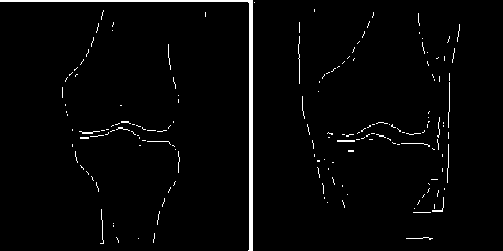
So we select the Sobel algorithm to do the edge detection. The Sobel operator [7] is as Table 1. Fig. 8 illustrates the result of CT image edge detection and the result of MR image edge detection.
TABLE I T able of S obel operator
|
-1 |
-2 |
-1 |
|
0 |
0 |
0 |
|
1 |
2 |
1 |
|
-1 |
0 |
1 |
|
-2 |
0 |
2 |
|
-1 |
0 |
1 |
(a) (b)
Figure 8 The result of edge detection.
-
(a) The result of CT image edge detection
-
(b) The result of MR image edge detection
-
E. Image Outline Processing
The MR images after edge detection contain the sharp and clear outlines of the leg, as Fig. 8(b) shows. Further preprocessing is needed to remove the outlines of the leg so that there are only outlines of bones left in the images.
To remove the outlines of the leg, we designed an outline processing algorithm. The idea is that image data saved in the matrix is processed line by line to remove the leg’s edge. In every line, the first and the last peak of the pixel values will be recognized as the leg's edges. The pixel values in the area of peak will be replaced by the average pixel values around the peak so that the leg’s outlines are removed.
The outline processing algorithm is as the following.
Input one line of image matrix
FOR i = 0; i < 200; i++
IF the pixel area of the first peak is detected go back 3 pixels from the pixel area store the 3 pixels go forward 3 pixels from the pixel area store the 3 pixels calculate the average value of the 6pixels
Replace pixel area with the average value
END IF
IF the pixel area of the last peak is detected go back 3 pixels from the pixel area store the 3 pixels go forward 3 pixels from the pixel area store the 3 pixels calculate the average value of the 6pixels replace pixel area with the average value END IF
END FOR
Read next line
After the processing, only the bone edges are left and abundant enough to do registration (see Fig. 9).
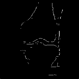
Figure 9 MR image after outline processing
As Fig. 8(a) shows, the leg outlines in the CT image is already removed after image blurring and image edge detection. So the CT image doesn’t need outline processing.
Ш. MI IMAGE REGISTRATION
After the images are preprocessed, we can do the image registration. To do image registration, we need get three parameters, horizontal shift parameter X, vertical shift parameter Y and rotation angle parameter a.
In our project, Powell Method (PM)[7] and Mutual Information (MI)[8] are adopted to calculate the movement parameters. Mutual information registration register images, by measuring the dependency of data from two different images. The formula is as the below:
I(A,B) = H(A) + H(B) – H(A,B)
= H(A) – H(A|B) (4)
= H(B) – H(B|A)
H(A), H(B) are entropy of variable A and B respectively, and H(A,B) is joint entropy, H(A|B) and H(B|A) are conditional entropy. I (A, B) is mutual information. If variable A and B are independent, I(A, B) equals to 0. The image intensity values in CT and MR images are used to calculate the relation of geometric position.
Powell search is an ideal directional search and also a conjugate gradient descent method. It consists of multiple iterations and every iteration does n+1 times one dimension search. n is the number of parameters in search function. In the iteration, start to search with initiate point X 0 , which is the origin in our solution, in d 1 , d 2 , …, d n directions to get the local minimum point X 1 . Thus the new direction is from X 0 to X 1 , in which the minimum point X2 can be calculated by one-dimensional search. Iterate this process with new start point X 2 .
the one-dimensional search used in Powell search starts from a point X n and using algorithm, golden section search, to calculate direction d n . then searches minimum point X n+1 from X n in direction d n . And then a new minimum point is searched from X n+1 in direction d n . The above step is repeated until get the best point.
Golden section search is a one-dimensional search, which calculates new point with 0.618 as a step. The initial search interval, for example, is [a 1 , b 1 ]. In the first iteration, points will choose X 1 = a 1 + 0.382(b 1 – a 1 ) and Y1 = a1 + 0.618(b1 – a1). In each iteration after, these two formulas can be used to calculate new points.
The algorithm of golden section search is as the following:
-
1. Assume the initial search interval is [a 1 , b 1 ] and the relative accuracy bound is L > 0, the initiate value X 1 , Y 1 , the function F(X, d) is the result of mutual information computation.
-
2. Set n = 1, X n = a n + 0.382(b n - a n ), Y n = a n + 0.618(b n - a n ). If b n - a n < L, then stop. Otherwise, if F(X n , d) > F(Yn, d), turn to step 3. If F(Xn, d) < F(Yn, d), turn to step 4.
-
3. Set a n+1 = X n , b n+1 = b n , X n+1 = Y n , Y n+1 = a n+1 + 0.618(bn+1 – an+1). Then calculate F(Yn+1, d), go to step 5.
-
4. Set a n+1 = a n , b n+1 = Y n , Y n+1 = X n , X n+1 = a n+1 + 0.382(bn+1 – an+1). Then calculate F(Xn+1, d), go to step 5.
-
5. Set n = n+1, go to step 2.
The function F(X, d) mentioned in one-dimensional search is to calculate two images’ mutual information value with parameter X and d. We can get the floating image’s movement parameters from input X and d. We can get horizontal and vertical movement from the distance between the origin and x and obtain angle rotation from direction d, which is a fixed number in each iteration of one-dimensional search.
The workflow to get the three movement parameters is like Fig.10. The CT and MR images after preprocessing are used as input of our image registration. PS and MI are performed in a loop until the maximum MI value is found. Then we get the three movement parameters, X, Y and a .
The three movement parameters, X, Y and a , are used to adjust the original CT images. The CT image’s coordinate transformation algorithm[9] is defined as
S ' = A S
S' = [ X ' Y '1 ] r
S = [ X о Y o^
cos a sin a X
A = - sin a cos a
Y
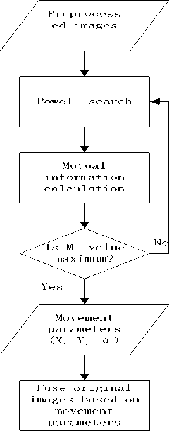
Figure 10 the flowchart of image registration
S is the transformed coordinate matrix. S is the original coordinate matrix. A is transform matrix, in which is rotation angle and X, Y are movement parameters.
Then the below algorithm is adopted to fuse the original MR image and the transformed CT image to compose a new image.
R * wr + F * wf = N
( w r + w f = 1 )
R is reference image (the original MR image) pixel value and F is floating image (the transformed CT image) pixel value. wr is the weight of reference image pixel value, and wf is the weight of floating image pixel value. In our case, both wr and wf equal to 0.5. N is the new image pixel value created from R, F.
-
II. EXPERIMENTAL RESULTS
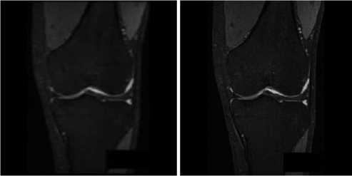
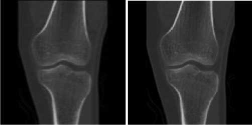
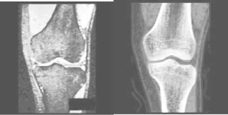
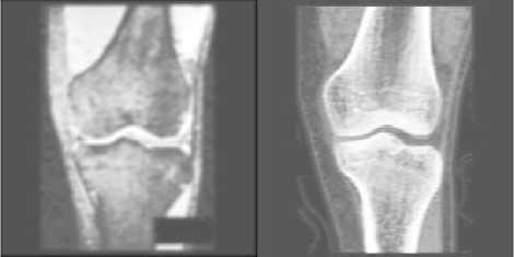
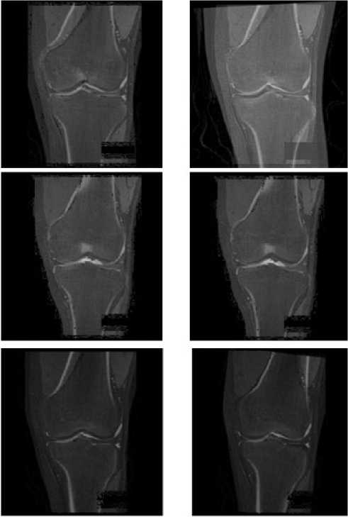
We compare the image registration results without preprocessing and the ones with preprocessing (see Fig. 11). Both of the registration solutions utilize the same image registration solution based on Powell Method and Mutual Information, and use MR images as the reference images and CT images as the floating images.
We selected three sets of images to do the experiment (see Fig. 11). Fig. 11(a), Fig. 11(c) and Fig. 11(e) show the image registration results without image preprocessing. Fig. 11(b), Fig. 11(d) and Fig. 11(f) show the corresponding image registration results with image preprocessing.
Comparing Fig. 11(a) with Fig.11 (b), we can see that the registration with preprocessing has better result, especially for the joint groove. Comparing Fig. 11(c) with Fig. 11(d), we cannot see explicit difference between the registration result without preprocessing and the one with preprocessing. Both of the results have accurate match. It’s because that the MR and CT images here coincidently have similar perspectives. Comparing Fig. 11(e) with Fig. 11(f), we can see that preprocessing improves the registration accuracy largely. In Fig. 11(e), most of bone edges from the CT image and the MR image cannot overlap with each other. In Fig. 11(f), the registration accuracy is much higher, especially for the left side of upper bone, the right side of lower bone and the joint groove. Admittedly some small parts of bone edges from the CT image and the MR image cannot overlap with each other. But considering bone edge data cannot be changed, this result is acceptable and has evident improvement than the one without BEBDO preprocessing.
Overall, the results of image registration with BEBDO preprocessing have some improvements comparing with the ones without preprocessing. Why? Table II can give us some hints.
Table II compares the movement parameters from image registration without preprocessing with the ones from image registration with preprocessing. From Table Π, we find that the rotation angles calculated from the image registration without preprocessing are all close to zero. It is because that the algorithm registers all the content in images and the interference from adipose, muscles and other soft tissues is not eliminated. After removing redundant information via BEBDO preprocessing, images registration based on bone information has better precision. From table II, you can see that the rotation angles generated for image set I and III are prominent. Using the movement parameters generated with preprocessing to fuse the knee joint images, we can get higher accuracy in bones alignment.
(a)
(c)
(e)
(b)
(d)
(f)
-
Figure 11 the results of image registration.
-
(a) The 1st image registration result without image preprocessing
-
(b) The 1st image registration result with image preprocessing
-
(c) The 2nd image registration result without image preprocessing
-
(d) The 2nd image registration result with image preprocessing
-
(e) The 3rd image registration result without image preprocessing
-
(f) The 3rd image registration result with image preprocessing
W. Conclusion
To do an analysis of the stress distribution on knee joint, it’s necessary to register MR and CT images. In the registration, the most important is to keep and match bone’s information first. To eliminate the interference of cortex fat or muscles on image registration, we design an image preprocessing solution BEBDO to preprocess the images. The BEBDO preprocessing is composed of image blurring, image enhancement, image blurring,
TABLE Π
MOVEMENT PARAMETERS FROM IMAGE REGISTRATION
|
X |
Y |
ANGLE |
||
|
SET1 |
original |
1.00003 |
-1.00003 |
0.00001 |
|
Preprocessed |
0.99997 |
0.99996 |
2.96449 |
|
|
SET2 |
original |
1.99957 |
11.99810 |
-0.00028 |
|
Preprocessed |
0.99085 |
12.02493 |
-0.01564 |
|
|
SET3 |
Original |
0.00000 |
0.99999 |
-0.00004 |
|
Preprocessed |
4.12766 |
2.95095 |
-6.12823 |
image edge detection, and outline processing. Then we use MI to do image registration.
The experiments that we have done proves that the image registration with BEBDO can align bones better than the one without BEBDO. The BEBDO preprocessing can improve the accuracy of image registration.
References The Registration of Knee Joint Images with Preprocessing
- Paul Viola and William M. Wells Ⅲ,”Alignment by maximization of mutual information” [J].International journal of computer vision, vol 24 No. 2,1997:137~154;
- B. Likar, F.Pernus,”A hierarchical approach to elastic registration based on mutual information”, Image and vision Computing,19, 2001:33~44;
- Josien P. W. Pluim, J. B. Antoine Maintz and Max A. Viergever, “Image registration by maximization of combined mutual information and gradient information”, Medical image computing and computer-assisted intervention – MICCAI 2000, 2000, Volume 1935/2000 : 103-129
- Chen Xiaoyan,Gu Jia,Li Songyi,Shu Huazhong, Luo limin, “A method based on mutual information and gradient information for medical image registration” .Journal of Southeast University(English Edition),2003,19(1):35~39;
- Mattew Mellor.Micheal Brady. “Phase mutual information as a similarity measure for registration” Medical Image Analysis,vol 9, issue 4, August 2005:330~343;
- Gonzalez, Rafael C., Woods, Richard E. Eddins, Steven L., Digital image processing using MATALB, Published by Pearson Prentice Hall, Upper Saddle River, NJ USA, 2004.,
- Study and Comparison of Various Image Edge Detection Techniques, Raman Maini, Himanshu Aggarwal, International Journal of Image Processing (IJIP), Volume 3, Issue 1, Febuary 2009
- Klaus Engel, Markus Hadwiger, Joe Kniss, Christof Rezk-Salama, Daniel Weiskopf, “Real-Time volume graphics” 2006, A K Peters, Ltd, P112
- John H. Mathews, Kurtis K. Fink, Numerical methods using matlab, 4th edition,2004, Prentice-Hall Inc.: 434-439
- Frederik Maes, Andre Coolignon,Dirk Vandermeulen, Guy Marcha, and Paul Suetens, “Multimodality image registration by maximization of mutual information”, IEEE transactions on medical imaging, vol 16, No. 2, April 1997
- Zhang Yujin, Image engineering (Ⅰ) image processing (second edition), Tring Hua Univeristy Press, P58 -61
