The Research of the Measures Algorithm of the Parameter of the Cutter

Author: S. Ya-ceng, C. Jing, T. Jun-wei
Journal: International Journal of Image, Graphics and Signal Processing(IJIGSP) @ijigsp
Article in issue: 1 vol.3, 2011.
Free access
Edge detection is the most basic problem in the process of image processing. The precision of traditional edge detection algorithm is not very high, it unable to meet the high precision need of modern industrial test technology. In order to overcome the deficiency, this text proposed subpixel edge detection algorithm based on the function curve fitting-Gauss fitting of gradient direction sub-pixel edge detection algorithm. According to the gradient distribution of the image, this text use gauss curve fitting the edge in order to realize the sub-pixel location. This text compared this algorithm with sub-pixel edge detection based on the LOG operator and sub-pixel edge detection based on the quadratic, and draw that this algorithm not only have the short running time and high efficiency, but also has proved that the algorithm has rotation invariant through the experiment. It is that pattern recognition and picture measure the important pretreatment means in the course to follow the method at the border, contradiction at accuracy and speed that but follow the method and exist at the traditional border. To above-mentioned problems, this text proposes following algorithms at the border based on model, and then try to get the diameter of the cutter. The experiment shows this algorithm at the realization border that can be very good and follows, measure the comparison of the algorithm through two kinds of diameters, drawing the running time of least square method shorter, efficiency is relatively high.
Sub-pixel, edge detection, gauss fitting, image processing, least square method
Short address: https://sciup.org/15012090
IDR: 15012090
Text of the scientific article The Research of the Measures Algorithm of the Parameter of the Cutter
Published Online February 2011 in MECS
Computer vision detecting technology is a new technology and developed in the field of testing in recent years. Machine vision use computer to realize the visual functional of human, the perception, recognition and understanding of the objective world[1-2]. Edges are the basic characteristics of the image, and edge detection is usually the first phase of image procession of visual system, is the key of the early treatment technology of the
Bureau of Science and Technology of Shaanxi Province for supporting of Foundation (2010K08-16)
Bureau of Special scientific research plan project of Shaanxi
Province for supporting of Foundation ( 2010JK600 )
Foundation of key subject construction of Shaanxi Province image procession, the correction and reliability of the results directly influence the understanding of the visual system to the object world.
-
A. Edge detection
The traditional edge detection methods such as sobel operator, LOG operator and canny operator can only achieve pixel level when localize the image, due to the rapid development of the application of industrial test, the requirement of accuracy is continuously improved, subpixel edge detection and positioning technology was widespread concern rapidly[3-5]. The proposed sub-pixel edge detection algorithm can break through the restriction of the resolution of the CCD camera, and it makes the image edge localization reach sub-pixel level. According to the classification of mathematical model, the existing sub-pixel edge detection algorithm can be divided into three categories: interpolation method, fitting method and torque method[6-8]. These algorithms adopts the traditional edge detection algorithm to coarse position, and all use pointers to process, it need to spend a lot of time, so this paper proposes a new sub-pixel edge detection methodGauss fitting of gradient direction sub-pixel edge detection algorithm, and it can solve the above problems well.
-
B. Boundary tracking
Boundary tracking is a kind of method of image segmentation based on gradient, click and set out from a piece of border of the gradient picture, through confirming the next and new border to click to the analysis of some neighborhood of a piece of border before, until getting back to the starting point. Following purposes to fit with fitting sharply, arc at the border is all for winning the outside outline characteristic of the picture, prepare for the thing that the form and parameter of the picture are analyzed. Boundary tracking process is a complicated process, we must first find boundary starting point, enter the ring of following after finding the starting point. In following the ring, take out the data that neighborhood picture element is lighted for the central point for some of border that is found newly, therefore come to differentiate the next and new border to click, if exist at the new border and click, write down one yard of value of its chain; if does not have new border that is clicked, enter absolutely a bit and deal with. In the realization of the procedure, above-mentioned methods have certain defects. For example, while acting as and meeting a bit in more isolation, will cause the death circulation of the procedure according to abovementioned methods, it is unable to follow to cause the border; during the process of following at the border, because has not written down at the border that has been already followed and clicked, make procedure to with circle follow repeatedly on one side, cause procedure unnecessary redundancy.
Because it is generally all that four neighborhood, eight neighborhood are followed to follow at the border, carry on the arc and will consume a large amount of time to fit again after these are concluded, and four neighborhood, eight neighborhood is it is it will enter circulation cause border to be unable to is it go down to follow very much at breaking a bit to present to follow. In order to save the time of operating, and unlikely to extremely circulate, subject this adopt based on model border follow algorithm, follow with fitting sharply border, arc go on at the contract of planning, the method to revise the straight line or the arc model constantly tries to get the angle or diameter of the cutter.
-
II. T HE SUB - PIXEL EDGE DETECTION
-
A. The principle of sub-pixel edge detection
The thought of gauss curve fitting sub-pixel edge detection algorithm is first choose some points in the edge of the image, then get the grey value of these points, finally obtained corresponding gradient value according to the grey value.
The gradient curve of the image edge on the direction of gradient presents a gauss distribution. If the text use edge detection operators directly extract the edge of the image, only need to find which grey of the pixel coordinates has changed biggest. But the pixel coordinate which has the biggest change of grey value are not necessary the extreme value point of the gauss curve, and may often not extreme value point. As shown in Fig.1, we often think 0 point is the image edge point, but from the graph can clearly see that the actual marginal location
x point is not the 0 point, but g . In order to improve the accuracy of measurement system, the text achieves the precise location point by using gauss fitting sub-pixel edge detection algorithm.
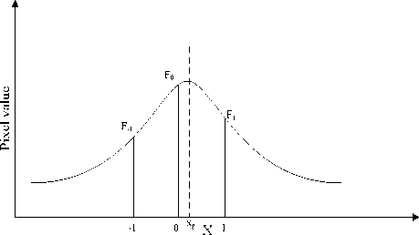
Fig.1 The gauss curve and extreme value point
The dots which are got from gradient are discrete, so must be fitting for a continuous curve, the coordinates of symmetric axis obtained through the fitting curve, the derivative along a gradient of gray approximation for gauss distribution, and the center of the gauss distribution or the average of the gauss distribution is in the place where the grey changes biggest along the gradient direction, also is the place of the edge. So only need seek the average of the gauss distribution, then can accurate positioning sub-pixel edge coordinates.
The gauss curve expression is:
( x - Ц ) 2
1 9,t2
У = ,— e 2 ° (1)
V 2 пб
Ц -the average (i.e. position parameter)
О -Standard deviation
This type of expression directly be fitting is very difficult. The purpose is to find the vertex positions of the curve, let’s have a transformation with the gauss curve, both logarithm get next type:
( x-ц) 1
ln y =-----+ ln
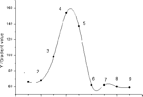
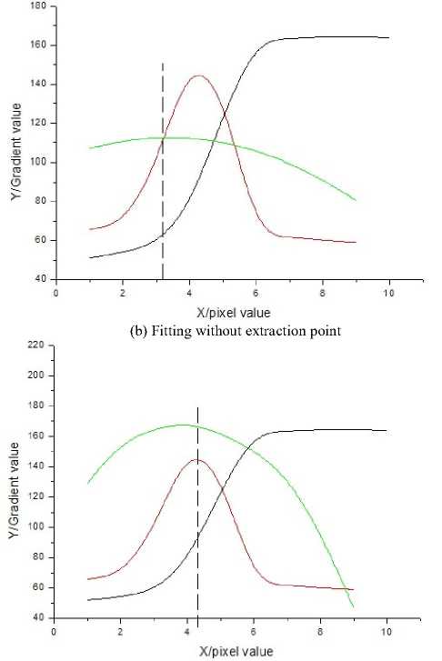
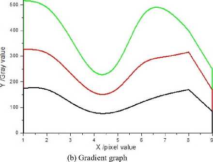
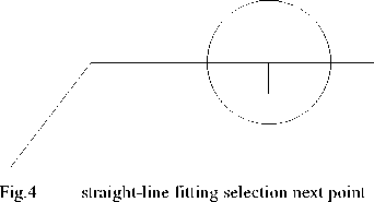
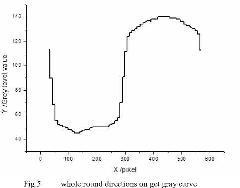
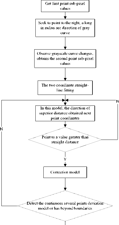
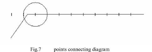
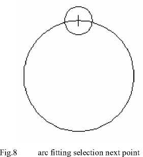
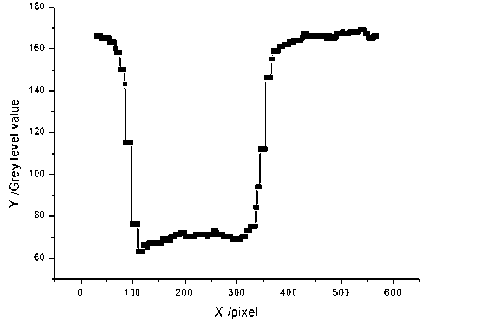
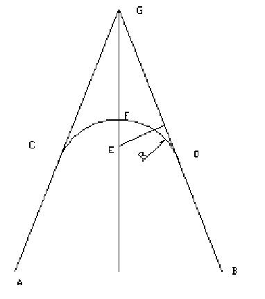
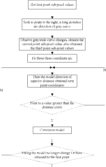
2°2 2r° It can find out the type is similar to y = ax2 + bx + C, it is a typical conic section tox . So that we can take the value after the logarithm fitting out parabola, seek the vertex coordinates, to simplify calculation. The equation used to fitting on the edge is y = ax2+ bx + C , get the parameter a, b, C by the principle of least square method, and make the sum of square of error of S minimum n S = ^ (У - axi - bxi - C)2(3) i=1 Seek partial differential for S respectively to a,b,c , and make its partial differential equal to zero, d x e - f x g a =---—— h x d - g x g <b=f-gxa d 1n nn c=-(Ё y - a xE x2 -bxE x) n i=1 i=1 There into n nn d = n E x?-E xiE Xi i=1 i=1 i=1 n nn e=nE x2 y-E x2 E y i=1 i=1 i=1 n nn * f=nE xy-E xiE yi(5) i=1 i=1 nnn g=n E xi3-E xi2 E xi i=1 i=1 n nn h=n E xi4-E xi2 E xi2 i=1 i=1 i=1 Should pay attention to the former gauss curve is fetch logarithm, namely after the pixel values of fetch logarithm with quadratic curves. It should notice that y should use ln y replace. Then give Д and <7 : Ц = -b / (2 x a) * / -1 (6) 7 = I V2 xa Ц----the value of sub-pixel value Due to the same edge points with any direction of the pixels are equal, namely in the same edge image it has rotation invariant. Therefore, the sub-pixel value have no request for the direction of the line, any direction will do. The derivate gray values obtain the gradient values; it will do gauss fitting according to the gradient value. Due to not all detected points are useful, as shown in Fig.2 (a), One of the 1,2,3,4,5,6,7 point is useful, but one of 8,9point is not useful. If use the useless points will affect our fitting results, as shown in Fig.2 (b), all points was in fitting, the red curve is the gray curve in the picture, blue curve is gradient curve, green curve is the fitting curve, linear is the symmetry axis of gauss curve, the correct fitting should be the symmetry axis of gradient curve and fitting curve is overlap, obviously Fig.2 (b) is not correct. In order to detect the edges correctly, must choose the useful points from all points, in Fig.2 (a) only use 1,2,3,4,5,6,7 points, the fitting results are shown in Fig.2 (c), and linear is also the symmetry axis of gauss curve in this picture. Which point is useful should be selected according to the gradient function. a 2 4 6 8 10 X /pixel value (a) Gradient graph (c) Fitting with extraction point Fig.2 The extraction of fitting point According to the shape of the gradient function curve, there are judging rules as follows: (1)From the first point, ordinal calculates the value of ti = g (xi+1) - g (xi) , if ti< t£ ( t£ is a threshold setting by yourself), ti+1 > t£ , then note the right time xi, that point is a starting point; (2)If ti > t£, ti+1< t£, ti+2> t£ , continue calculating the behind point; (3)If tt > t£, t t+1 < t£, t t+2 < t£ , then note the right time Xi+1, that point is the ending point. According to the above rules to screen the useful points for us, then fit the gauss curve through the selected points. This algorithm is using c# language writing program in VS2005 platform, use this platform to do some experiments to cutter image. First, select three directions lines which through the same point, seek the gray curve of the three direction lines, as shown in Fig.3 (a), the difference between the three lines is that the degree of the title is not the same, draw the gradient curve, as shown in Fig.3 (b), the position of symmetry axis of three gauss curves is the same, and three different directions of the linear sub-pixel values are the same. 600 1 TABLE I. THE SUB-PIXEL VALUES OF DIFFERENT ANGLES OF THE LINEAR Angle Sub-pixel location Angle Sub-pixel location 30° 742.38 120° 742.38 45° 742.38 135° 742.38 60° 742.38 150° 742.38 90° 742.38 180° 742.38 Secondly, in the same picture of 2592×1944 image, get the sub-pixel location by gauss fitting sub-pixel location algorithm, the sub-pixel location algorithm based on the LOG and the sub-pixel location algorithm based on quadratic, respectively get the sub-pixel location and time as shown in TABLE П. It can be known from TABLE П, the sub-pixel location value of three sub-pixel edge detection algorithm is almost the same, but the running time of three algorithms is difference. Gauss fitting subpixel edge detection algorithm has short running time and high efficiency. TABLE II. THE COMPARISON OF THE RUNNING TIME OF THREE SUB-PIXEL EDGE DETECTION ALGORITHM Sub-pixel edge detection algorithm Sub-pixel edge detection algorithm based on LOG operator Sub-pixel edge detection algorithm based on quadratic Gauss fitting sub-pixel edge detection algorithm Calculated value (pixels) 742.39 742.35 742.38 Running time(ms) 145.6379 81.1562 80.6392 X/pixel value (a) Gray graph Fig.3 The gray image and the gradient image of three directions Ш. Ask the diameter of the cutter Measure the position where the algorithm gets the first point in some place of picture edge through the inferior picture element edge at first, regard this point as the centre of a circle[9], obtain grey level value as the whole round direction of the radius long (establish by oneself ) by some. As shown in Fig.4 show. This text first gets the sub-pixel value of the 90° direction in a straight, the results is 742.3803, through the sub-pixel coordinates, rotating linear to a certain Angle get a new line, through the new line edge point, take its grayscale value, get gradient value, then according to the gradient value get the sub-pixel value. The angles were taken as shown in TABLE I, and the sub-pixel values of these directions were got, it can be known from table1, the values are constant, thus the sub-pixel edge detection algorithm has the rotation invariant. Can know by Figure1, cross the border twice whole round, therefore there should be two grey level changes in the grey level curve got. As Figure 2 shows. In Fig.5 gray place first select a point, transfer inferior picture element edge measure algorithm get accurate position of point this then, can get the coordinate of the second point, transfer the inferior picture element edge and measure the accurate position where the algorithm gets the second point according to the coordinate of the second point, can plan to try to get the equation of the straight line in worthwhile law with the straight line by these two points[10-12]. Because least square method has planned to already get very good application in the worthwhile law in the straight line, so the planning to adopt least square method in worthwhile law sharply of a subject. Set equation of the straight line as y = ax + b , ask for parameter a, b by least square method principle, and make the square and minimum of error s . n S = E [y- ( ax+ b )]2 (7) i=1 The difference to a,b the having type is asked and simply led, make it lead function equal zero, solve equation group take not to lean towards nnn УxE y-n E xy a = —м---м-- nnn < E xE x- nE xix i=1 i =1 nn E y- a E xi b = J=i n Choose some next coordinates in the first-class distance of direction of this straight lines, transfer the inferior picture element edge and measure the exact value of getting, if this point is smaller than threshold value to the distance of the straight line model that just fitted (establish by oneself), model then needn't revise , continue direction first-class distance must produce the next point in model; If this point is greater than threshold value to the distance of the straight line model that just fitted , fit sharply to these three points, it revise model, it is then in model that is new is the first-class in direction from choice next point, repeat above-mentioned operation. If several continuous points already appearing at the border or measuring out in point measured deviate from the model very big, stop searching for, the slope of straight line at this moment, namely for the slope of our required straight line, as Fig.6 shows. C. Experiment course Y Fig.6 Boundary tracking and straight-line fitting flowchart When the slope of a straight line is got, should measure the next straight line automatically, last some got with this straight line is as the centre of a circle, it is long (the selected value before this) as the radius by some, try to get the grey level in this round direction, drew the grey level curve, thus received the first point on the next straight line, transfer the inferior picture element edge and measure and revise the first coordinate value, as Fig.7 shows. And then by asking the first straight line method to try to get the slope of the second straight line. Try to get the contained angles of two straight lines according to the slope of two straight lines. tan a = k1 - k2 1 + k1 k2 Among them it is the slope of two straight lines respectively. This algorithm is the procedure utilizing C language to be written on VS2005 platform, carry on the experiment in shooting the good cutter picture with this platform. Measure the result to the cutter angle as form TABLEffi shows. TABLE III. ANGLE MEASUREMENT RESULTS (UNIT: °) Measure the ordinal number 1 2 3 4 Determine the angle 89.31° 60.85° 45.03° 29.79° Actual value 90° 60° 45° 30° To the picture of 2592* 1944, the running time of the whole procedure is 235.47ms, running time is relatively short. IV. Ask the diameter of the cutter Measure the position where the algorithm gets the first point in some place of picture edge through the inferior picture element edge at first, regard this point as the centre of a circle[13], obtain grey level value as the whole round direction of the radius long (establish by oneself ) by some. As Fig.8 shows. Can know by Fig. 8, cross the border twice whole round, therefore there should be two grey level changes in the grey level curve got. As shown in Fig.9. Fig.9 whole round directions on get gray curve In Fig.9 gray place first select a point, transfer inferior picture element edge measure algorithm get accurate position of point this then, can get the coordinate of the second point , transfer the inferior picture element edge and measure the accurate position where the algorithm gets the second point according to the coordinate of the second point, according to the accurate position of the second point , and then get the coordinate of the third point with the same method, can plan to try to get the equation of the arc in worthwhile law with the arc by the coordinates of these three points. Ask the arc diameter method to have cutting method of louses and least square method. (1) Cutting method of the looks Fig.10 tangent methods for cutter diameter The principle of the cutting method of the looks is tried to get with the arc at first two tangent straight lines looks is relatively clicked in G, pass G is it make two horn bisector GF of straight line these to order, Ei is it a bit, pass Ei some perpendicular to make GB to fetch at GF, like d > EtF , last some pieces of ones that fetch, until dt > EF, dt+1 < Ei+1 F , centre of a circle lie between Ei with Ei+1. (2) Least square method The coordinate is (Xi, yt), i = 1,2,..., N that measurement is lighted, correspondent to X1, X2 , .., Xn ,arc coordinate y value respectively y1 , y2 , .. , n yn . When the function F = E(y - yi)2 i=1 value is minimum, call arc(x, y, r) is the least square method arc of this curve to fit. This text is it is it is it get minimum two radius the square of incomplete the square of difference and minimum goal to order to examine to adopt promptly, can get the round centre of a circle (xc , yc ) , radius rc , the expression formula of the coordinate of centre of a circle is: Xc = [(Q-T2/N)(W + V-S(P + Q)/N)-(H - ST / N)( Z + U - T (P+R)/N)] /[(2P - 2S2/ N)(Q - T2/ N) -(2H - 2ST / N)(H - ST / N)] yc = [(p - S 2/ N)(Z + U - T (P + Q)/N) -(H - ST / N)(W + V - S(P + Q)/N)] /[(2P - 2S2 / N)(Q - T2 / N) - (2H - 2ST / N)(H - ST / N)] The expression formula of the radius is: rc = V xc2 + yc2 - 2 Sxc IN - 2Tyc IN + (P + Q) N (12) n Among them S = E Xi i=1 n T=E yi i =1 n p=E X2 i =1 n U=E Xi y^ i =1 n V=E X^yf i =1 n H=E X-yi- , i=1 n Q = E yi2 , i =1 n w=E x3 , i=1 n Z=E y3 - i =1 Least square method that radius measure calculate simple, fast, have noise when interfering, need fetching measurement more and fit . The cutting method of the looks is relatively complicated, but calculates the precision can change the step to improve but progressively long. This subject adopts the border based on model to follow algorithm and arc to plan to go on at the same time in worthwhile law, can remedy the defect of least square method , so a subject adopts least square method. In direction first-class distance of arc this choose next some coordinate, transfer inferior picture element edge measure the exact value of getting, if this point is smaller than threshold value to the distance of the arc model that just fitted (establish by oneself), model then needn't revise , continue direction first-class distance must produce the next point in model; If this point is greater than threshold value to the distance of the arc model that just fitted , carry on the arc and fit to these four points, it revise model, then in model that is new is the first-class in direction from choice next point, repeat abovementioned operation. If several continuous points already appearing at the border or measuring out in point measured deviate from the model very big, stop searching for, the diameter of the arc at this moment, namely for the diameter of our required cutter, as Fig. 11 shows. Y Fig.11 boundary tracking and circular-arc fitting flowchart This algorithm is the procedure utilizing C language to be written on VS2005 platform, carry on the experiment in shooting the good cutter picture with this platform. If getting the diameter measured , must know what each distance that picture element represents is at first, namely picture element equivalent , standard one which we used is carried on standard at first, it is 762.1615 that the system examines the picture element had, then picture element equivalent is 0.0656028898. Shoot the picture with the same system; examine the diameter of the cutter, as form TABLED shows. TABLE IV. CUTTER DIAMETER MEASUREMENTS Measure the ordinal number 1 2 3 4 Measure the diameter ( pixel) 245.371 334.970 412.039 496.868 Measure the diameter (mm) 16.097 21.975 27.031 32.596 Actual value (mm) 16 22 27 32 As to picture 2592 x 1944 , the running time of the whole procedure is 241.92ms , running time is relatively short. V. Conclusion In order to improve the detection efficiency, this text didn’t adopt the traditional edge detection algorithms to coarse position, but take one point near the edge firstly, take a few points in that direction through that point, then use the gauss model fit the gradient value to get the subpixel value. And it verified that the sub-pixel value is the same with any direction by experiment, namely sub-pixel edge detection algorithm has rotation invariant. Compare the running time with other two sub-pixel edge detection algorithms, this algorithm has the shorter running time, high efficiency and stronger real-time and has a good application prospects in the field of cutting parameter testing. In order to improve the efficiency of measuring, this text has not adopted the traditional border to follow algorithms to carry on the localization, but follow and fit the border sharply; the arc goes on while drafting the contract, revise models constantly. And has verified result and time that the cutter angle is measured, the diameter measures through the experiment. Choosing least square method to fit through the experimental analysis of the theory, the running time on the edge is relatively short, the operation which draws an algorithm is fast, with high efficiency in speed, real-time character is strong; measuring the respect in the parameter of the cutter has better application prospects. ACKNOWLEDGMENT The work has been supported by Shaanxi Science and Technology Research and Development Program (2010K08-16), The work has been supported by Special scientific research plan project of education department of Shaanxi Province(2010JK600). The work is the foundation of key subject construction of Shaanxi Province.B. The extracting of the fitting points of gauss curve
C. The analysis of experimental results

A. Follow and fit the principle sharply at the border based on model
B. Theory method to ask cutter angle

D. Experimental data that the cutter angle measures
A. Based on the boundary tracking and circular-arc fitting principle
B. Ask the arc diameter theory method
C. Experiment course

D. Experimental result analysis
References The Research of the Measures Algorithm of the Parameter of the Cutter
- LIU Rui, CHEN Hong-wei. “An Improved Edge Detection Algorithm”. Science Technology and Engineering.Vol.9, pp.6395- 6398,Nov. 2009(in Chinese)
- COLEMAN S A, SCONTNEY B W, HERRON M G.. “A validated edge model technique for the empirical performance evaluation of discrete zero-crossing methods”. Image and Vision Computing,vol.25,pp.1315-1328,2007
- CHANG Zhi-xue,WANG Pei-chang,PANG Ling-bin, ZHANG Xiu-feng. “A Roof Edge Detection Method Based on Parabola Fitting for Cross Laser Image”. Opto-Electronic Engineering.Vol.36,.pp.93-97,May,2009(in Chinese)
- QU Ying-dong,LI Rong-de,YUAN Xiaoguang, CUICheng-song,LIQing-chun,YU Li. “Fast subpixel edge detection based on two Zernike moments operators with different mask sizes”. JOURNAL OF HARBIN INSTITUTE OF TE CHNOLOGY. Vol.41,pp.178-180,May 2009(in Chinese)
- ANGELA C, ALFREDO C, REMO S, et al. “Hyperbolic tangent algorithm for periodic effect cancellation in subpixel resolution edge displacement measurement”. Measurement,vol 42,pp.1226-1232,2009
- ZHAO Fang, LUAN Xiao-ming,SUN Yue. “Edge Detection Operators in Digital Image Processing”. Techniques of Automation&Applications.vol28,pp.68-72,2009(in Chinese)
- GAO Shi-Yi, zHAo Min hngZZOUan-Yanl,ZHANGLeil"Improved Algorithm about Sub-Pixel Edge Detection of Image Based on Zernike orthogonal Moments”. ACTA AUTOMATIC ASINICA. Vol34,pp. 1163-1168,SePtember2008(in Chinese)
- ZhAO P, QIANG N G, BANG P Z. “Simultaneous perimeter measurement for multiple planar objects”. Optics & Laser Technology, vol41, pp.186 – 192,2009(in Chinese)
- LIU Mei-hua,WANG Dong,LIU Hui-qiu. A improved method of contourtracing. Machinery Design & Manufacture.vol5,pp.45-47,May2008(in Chinese)
- SUN Xiang-yang, YAO Li, WAN Yan. Adaptive Corner Detection Algorithm Based on Linear Fitting. JOURNAL OF SHANGHAI UNIVERSITY OF ENGINEERING SCIENCE.vol23,pp.46-50,Aprial,2009(in Chinese)
- DENG Baosong,GAO Yu,YANG Bing,WU Lingda. A New Algorithm for Linear Features Extraction and Orientation. Computer Engineering.vol32,pp.198-202,July2006(in Chinese)
- XU Hai-tao,GAO Cai-xia. The Linear Fitting Algorithm. Computer Knowledge and Technology. Vol.5,No.4, pp.864-867 ,February 2009 (in Chinese)
- Yu Ming-cai, YANG Xun-nian, WANG Guo-zhao. Curve fitting by optimal biarc spline. Appl. Math. J.Chinese Univ. Ser.A.vol19,pp.225-232,2004(in Chinese)
