The Route Research of LED Road Illumination Based On Wireless Sensor Network

Author: Jian Liu, Xinjiang Shao, Deng Pan, Zhisen Wang
Journal: International Journal of Modern Education and Computer Science (IJMECS) @ijmecs
Article in issue: 2 vol.2, 2010.
Free access
Energy and environment conservation is one of hotspots all around world now. Light emitting diode (LED) road illumination based on Wireless Sensor Network (WSN) technology can not only reduces complexity for arrangement of cables and route construction process, but also show advantage of LED illumination well. Meanwhile, it is good for energy and environment conservation. Route construction is a crucial issue when we use WSN technology. In this paper, we present two network structures, introduce the route construction process of illumination area and derive total transmit power (TTP) of WSN. Then we analyse impact of some factors on normalized TTP and do computer simulation to evaluate them.
Wireless sensor network;LED road illumination;Multi-hop self-organizing network;Route
Short address: https://sciup.org/15010057
IDR: 15010057
Text of the scientific article The Route Research of LED Road Illumination Based On Wireless Sensor Network
Published Online December 2010 in MECS
Nowadays, energy and environment conservation and green-lighting are promoted. LED road illumination with energy-saving, high luminous efficiency and luminous intensity replace traditional road illumination [1, 2]. As we know, manual control, time control and power line carrier are traditional control road illumination ways which cause arrangement of cables and networking troubles to us. High cost and maintain difficulty also should be taken into account.
How to efficiently control the LED lighting to show its advantages, and overcome disadvantages of traditional illumination way, at the same time, achieve the objective of energy saving is an issue that needs to be solved.
Due to the maturation and application of WSN technology, we are familiar with it. There are many nodes in WSN system. The nodes can extend network rapidly without manual intervention. Each node cooperates to transmit or exchange information well through wireless link [3, 4]. In this paper, we utilize WSN technology to control LED road illumination. On the one hand, this way can not only reduce complexity for arrangement of cables, but also make networking more convenient and faster than ever before. On the other hand, it makes up for disadvantages of traditional illumination way. It’s good for energy and environment conservation.
The remainder of this paper is organized as follows, Section II presents system construction. Section III shows route construction of illumination area. Section IV derives TTP of WSN based on route and evaluation for TTP. Last section draws conclusions.
II . SYSTEM CONSTRUCTION
In this paper, we introduce two ways of system construction as follow.
-
■ A. System structure one
As Fig.1 shows LED road illumination system consists of LED illumination based on WSN technology, cellular network and control center. There are center control module, illumination module, fault detection module, sensor module and communication module. To compare Center Point (CP) with Center Node (CN), Center Node owns cellular network Module. The main functions of CP are collecting environment parameters, communicating with control center through cellular network, transmitting order information from control center, analyzing and calculating date. The main functions of CN are collecting environment parameters, communicating with node or center node, analyzing and calculating date.
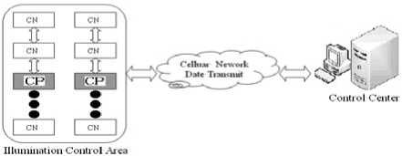
Fig.1 Road illumination network structure one
The information collected by CN is transmitted to CP with multi-hop route. Then CP communicates with control center through cellular network. According to special command, control center can send order to CP.
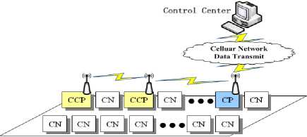
■ B. System structure two
As Fig.2 shows LED road illumination system consists of LED illumination area based on WSN technology, cellular network and control center.
Illumination Control Area
Fig.2 Road illumination network structure two
There are CP, Child Center Point (CCP) and Child CN in illumination area.
-
III. ROUTE CONSTRUCTION OF ILLUMINATION AREA
-
■ A. Route construction process based on System structure one
In this part, we will analyse route construction process of illumination area and derive TTP of WSN based on two different route constructions. Firstly, as route construction process of system
Fig.3 shows structure one.
#11-2
+
М)’ T #11'
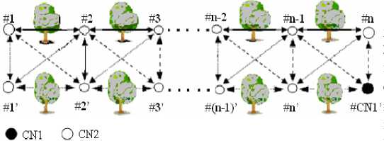
Fig.3 Environment schema of system structure one
-
♦ Step1 Node identification
Each node transmits pilot signal (PS) of same frequency in PS channel. Meanwhile, each node utilizes PS power to calculate required transmit power Pt , req .The required transmit power is given by
P treq ( j , i ) = P req + [ P t ( i ) — P r ( j )] , (1)
where Pt , req is the required transmit power from sending node # i to receiving node # j , Preq is threshold power of receiving node # j , Pt ( i ) is transmit power of sending node # i , Pr ( j ) is receive power of receiving node # j , Pt ( i ) - Pr ( j ) is path loss between sending node # i and receiving node # j .
Every receiving node need feed back required transmit power to sending node after calculation. At the same time, the sending node writes down the node address of return information node. We assume that
-
♦ Step2 Transmitting route construction message
Uplink(CN to CP), the content of route construction message includes (a)source node address, (b)forwarding information address, (c)center node address, (d)the number of hops,(e)transmit power, (f)total transmit power along the route.
Downlink(CP to CN), the content of route confirmation message includes (a)center node address, (b)source node address, (c)forwarding information address, (d)route confirmation.
-
a. Each node transmits route construction message to one path of lowest power consumption. The path is confirmed by Step1.
-
b. Receiving node # j receives route construction message from sending node# i . TTP is given by
H
P = ^ P , (2)
-
h = 1
where h is number of hop, h e (1,2,3... H ).
-
♦ Step3 Route confirmation and construction of route table
Route construction message of every node is transmitted to center node through multi-hop route. Then CP not only registers the optimum route, but also sends route confirmation message to each CN.
-
♦ Step4 Every receiving node should revert one
acknowledge message to sending node when it has received information. If sending node couldn’t receive acknowledge message normally, the route should be reconstructed. On the other hand, if climate changes unexpectedly, we could update the route table periodically.
-
■ B. Route construction process based on System structure two
Fig.4 shows environment schema. Route construction process of system structure two can be described as follow,
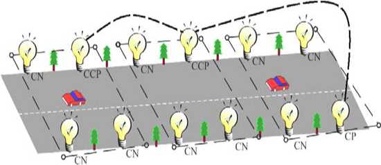
Fig.4 Environment schema of system structure two every sending node chooses only one path which has lowest power consumption to transmit route construction information.
First of all, we divide nodes into different groups; every group selects only one CCP automatically. Secondly, all information of CN is sent to CCP when they get some information. Then, CCP communicates with CCP of different group one by one. Finally, CP obtains the information. Next part, we will introduce the route construction in detail.
-
♦ Step1 Grouping
We assume that the number of system node is M ( m ≥ 4 and m is even), N is number of node in one group ( N ≥ 4 , n is even and N ≤ M ). We arrange the group from left to right, the result of ( M mod N ) belong to last group.
According to the address code which is stored in CP, CP could send Grouping Message (GM) to every node for grouping. GM includes © CP address, © group No., © member address code inside same group, © energy threshold.
-
♦ Step2 Selection of CCP
Every node compares member address code in GM with itself after grouping. The node who has minimum member address code becomes CCP first. Then, CCP send one broadcast message to nodes in same group. The broadcast message will inform node that who CCP is. As we know, the CP and CCP consume more energy than other nodes. In order to keep durability of WSN, we let the nodes become CCP in turn according to address code from minimum address code to maximum address code.
-
♦ Step3 Route construction
In this process, we divide route construction into two parts. One part is route construction between CN and CCP in same group. The other part is route construction between CCP and CP.
-
1. Route construction between CN and CCP in same group
Each CN transmits PS of same frequency in PS channel. PS includes © sending node address code, © sending node group NO., © transmit power. Meanwhile, each node utilizes PS power to calculate required transmit power Pt , req .The required transmit power is given by (1).Every receiving node need feed back required transmit power to sending node after calculation. At the same time, the sending node writes down the node address of return information node. We assume that every sending node chooses only one path which has lowest power consumption to transmit route construction information.
-
a. Transmitting route request (RREQ)
In every group, CN transmits RREQ along the optimum route.The content of RREQ includes ©source node address, ©forwarding node address,©CCP address,©the number of hops,©transmit power,©total transmit power along the route,©time to live(TTL). On the one hand, TTL prevents RREQ in WSN to form closed loop. On the other hand, WSN may use TTL to abandon RREQ, if the destination doesn’t receive the RREQ for a long time.
Then, every CN transmits the RREQ with Pt , req through optimum route which is determined by PS.
-
b. Send back route reply (RREP)
-
2. Route construction between CCP and CP
The content of RREP includes © CCP address, © source node address, © forwarding node address.
Each node need send back RREP to build an effective route when they receive RREQ. If sending nodes don’t receive RREP for a period, sending nodes will transmit RREQ again. We suppose that sending nodes transmit RREQ many times later, receiving nodes still don’t receive it. We think the receiving node doesn’t run normally. Then, the optimum route will be rebuilt again, and resend the RREQ to construct route.
CCP will transmit broadcast message for finding next CCP to build route. Broadcast message includes that © CCP (Sending) address code, © group No., © CP address code. Each CCP need send back RREP to build an effective route when they receive broadcast message.
The CCP transmit information one by one to CP. At last, the information will arrive at CP through CCPs which are from different groups. For every CCP, it records the optimum route which is from CNs to CCP and member address code of same group. CP will check whether any node lost in WSN when it receives RREQ. Then, CP send back RREP.
-
♦ Step4 Management of Route
We know that climate changes unexpectedly and the device often doesn’t run normally. So we should update the route table periodically.
IV ANALYSE OF TTP BASED ON ROUTE
-
■ A. TTP based on system structure one
We’ll analyze the transmission power of WSN in LED Illumination area after route construction. First of all, we analyse it based on system structure one.
For receiving node # j , the receive power is given by (3) [5, 6]
δ ( t )
Pr ( j ) = Pt ( i ) × ( Const × d - α × 10 10 ) , (3)
where Pt ( i ) is transmit power of node, α is the path loss exponent, δ ( t ) is shadowing loss with the standard deviation σ = 7 dB , d is distance between each node, Const =1.
Due to close distance and straight path between one node and the other node, we assume that Eq. (3) is electromagnetic wave model in free space. We could neglect the multipath fading. However, trees shadowing should be taken into consideration. Then Eq. (3) is expressed as below
р (
P( i ) =-- j- (4)
d -a io - 10
Transmit power of source node is given by
P (1) =---- ' (5)
d - a io - 1, j
P , total P norm = D
P one - hop
NH zz n = 1 h = 1
NH zz n = 1 h = 1
P
P req
5 i, j [ h ( n )]
- a 10
V d i , j [ h ( n )]10
N z n = 1
req
- a d i , j ( n )
_ 5i , j ( n )
10 10
<
A
f , j [ h ( n )]
da 10 '0
V d i , j [ h ( n )]10 J
Receive power Pr(j) at receiving node # j except for source node is given by fi^j
P r ( j ) = P ( i ) d - “ 10 - 10 (6)
i , j
To assume P r ( j ) = P req , then Eq. (6) is transformed to
Eq. (7) as follow
P
P ( i ) =----- req^ i- (7)
d " “ 10 - 1oV i , j
So TTP of one sending node is given by
P , total
H
=z h=1
( A
P req
d
-a i,j(h)
_ f , j ( h )
10 10
N z n = 1 d"", A n i , j ( n )
f , j ( n )
10 10
Fig.5 Impact of node number on normalized TTP of system structure one
then we could get the TTP of all nodes in system is given by
p , total
NH
=zz n=1 h=1
req
_ f , j [ h ( n )]
d~a 10 - 10
V i , j [ h ( n )] J
where n is number of nodes, n e (1,2,3... N ).
As Fig.5 shows с = 7 dB , d = 30 m , for different a . The information is transmitted along optimal path. With the raising the number of node, self-organizing and multi-hop route can obviously decrease the transmit power. It is helpful for saving system energy, and it is a good solution to solve the problems which traditional road illumination control ways cause.
We will analyse impact of some factors on normalized TTP and do computer simulation to evaluate them. In this paper, d is the distance between each node , d = 30 m . N is number of node, N = 50 . a is the path loss exponent a = 2.0,2.5,3.0 . 5 is shadowing loss with the standard deviation с = 7 dB . In order to normalized total transmit power Pnorm is defined as the TTP in system normalized by that of one-hop case.
P
P norm = p , where P total is given ЬУ Eq-(9), P norm
Pone - hop becomes
Fig.6 Impact of d on normalized TTP of system
structure one
As Fig.6 shows с = 7 dB , a = 2.5 , N = 50 .The information is transmitted along optimal path. We enlarge d step by step. Self-organizing and multi-hop route can obviously decrease the transmit power. WSN technology could save transmit power.
total _ Single
H
=z
h = 1
P req
_ 5 i , j ( ‘ )
d-a 10 10
V i , j ( h )
h e (1,2,3... H ).
Fig.7 Impact of a on normalized TTP of system structure one
Then, for one group, TTP of one group is given by
p., . =yy total_Group
req
5 , j [ ‘ ( n )]
d-a 10 - 1
V i , j [ ‘ ( n )] 1
,
N is number of node in one group, N e {1,2,3,...} .
For whole system, TTP of system is given by If M mod N =0,
= G ( g ) * £Z
P
+
d ,_ a 10
V i , j [ h ( n ), g ]
У
If M mod N ^ 0,
I . J . .
P a = ( G ( e ) - 1 ) f ZZ
P r
As Fig.7 shows a = 7 dB , d = 30 m , N = 50 .On the one hand, WSN has obvious effect to conquer the harsh environment when the shadowing is serious. On the other hand, WSN could significantly reduce TTP while a becomes larger. On the other hand, the WSN has strong ability to be adapted in the bad environment.
■ B. TTP based on system structure two
Secondly, we’ll analyze the transmission power of WSN in LED illumination area based on of system structure two.
For receiving node # j , the receive power is given by (3) ,
Due to close distance and straight path between one node and the other node, we assume that Eq. (3) is electromagnetic large scale model. We could neglect the multipath fading. However, trees shadowing should be taken into consideration. Then. Transmit power of source node is given by
P (A
P t (1) =--- -j- (11)
d;a io - 40
, j
To assume P r ( j ) = P req , Receive power P r ( j ) at receiving node # j except for source node is given by
P ( i ) =
P req
о. .
i,j d "a10 - 10
i , j
i , j [ h ( n ), g ]
(N-1)+(M mod N) H z z n=1 ‘=1

_ 5 , j ‘ ( n ), g ]
d 7 a 10 10
V i , j [ h ( n ), g ]
So TTP of single sending node is given by
( G ( g )
req
req
N + ( M mod N )) d i - a _ ";<‘ ( n ) g ]
10 10
2 1, i, j[h(n),g]
G is the number of grouping, G > 4 and G is even.
Then we will analyse impact of some factors on normalized TTP and do computer simulation to evaluate them. In this paper, M = 50 , d is the distance between each node( d = 30 m ), N is number of node in one group, a is the path loss exponent( a = 2.0,2.5,3.0), 5 is shadowing loss with the standard deviation с = 2,4,6 dB ).In order to normalized total transmit power Pnorm is defined as the TTP in system
Pttl normalized by that of one-Hop case P =-------or norm P ± one - Hop
P norm
'
P total
P „ one _ Hop
,where Ptotal
Eq.(15), P norm becomes
and P total are given by
total
total
-145
P norm
р „ one _ Hop
N req
Z^ s i, j ( n )
n = 1 d i ™ 10 -
, if M mod N = 0
total
total
-146
-147
P one _ Hop
N req
1 ^
, if M mod N ^ 0
-148
-149
n = 1 d,a 10^ i , j ( n )
-150
M=50 α =2 d=30m
N=6
In order to show the advantage or disadvantage of route from this paper, we show the other route for comparison. If information collected by CN is transmitted to CP with multi-hop route directly. The P ' norm is given by
-151
-152 0
4 σ
norm
total
Multi
one _ Hop
N
I- n=1 d
P req
5 i, j ( n )
a m--10-, j ( n ) 10
Fig. 9 Impact of a on normalized TTP of system structure two
As Fig.9 shows M = 50 , a = 2 , d = 30 m , for different a and N . We enlarge parameters step by step. WSN has obvious effect to conquer the harsh environment when the shadowing is serious. That’s to say, WSN has strong ability to be adapted in the bad environment. WSN technology could save transmit power.
-143
-144
-145
-146
-147
-148
-149
-150
-151
-152
T
M=50 σ =4dB α =2 d=30m
N=4
N=6
N=8
N=12
N=14
N (the number of node in one group)
Fig.8 Impact of N on normalized TTP of system structure two
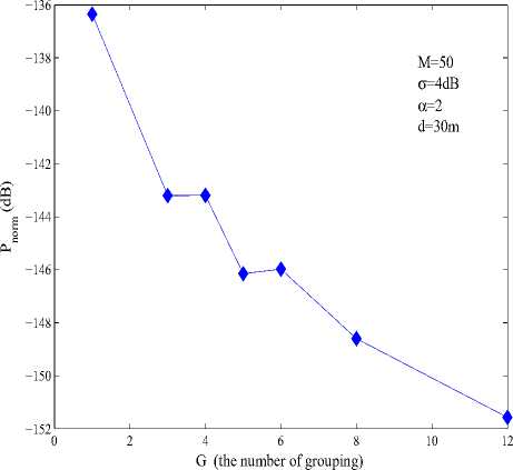
Fig.10 Impact of G on normalized TTP of system structure two
As Fig. 8 shows M = 50 , a = 4 dB , a = 2 , d = 30 m , for different N .The information is transmitted along route. With the decreasing the number of node in one group, grouping and multi-hop route can obviously decrease the transmit power. It is helpful for saving system energy, and it is a good solution to solve the problems which traditional road illumination control ways cause.
As Fig. 10 shows M = 50 , a = 4 dB , a = 2 , d = 30 m . We change G step by step. With the raising the number of grouping, WSN could reduce energy significantly. So, if we increase G or decrease N , it is helpful for saving energy.
V.CONCLUSIONS
In this paper, we utilize WSN technology to control LED road illumination intellectually. Especially , we draw two system constructions, route construction process, analyze of TTP based on different route in illumination
area. On the one hand, due to self-organizing and multihop route of WSN, this method can not only reduce complexity for arrangement of cables, but also make networking more convenient and faster than ever before. It will also significantly save power. In a word, it is meaningful that LED road illumination is controlled intellectually by WSN technology.
ACKNOWLEDGMENT
References The Route Research of LED Road Illumination Based On Wireless Sensor Network
- Edgar H. Callaway, Wireless Sensor Network Architecture and Protocol,1st ed, Electronics Industry Press,2007.
- Qingde Yang and Ya Kang, LED and Engineering application, 1st ed, Posts and Telecom Press,2007.
- Hong Liu, Green Light, China Electric Power Press,2009.
- Holger Karl, Wireless Sensor Network Architecture and Protocol, 1st ed, Electronics Industry Press,2007.
- Lingxing Chen, Ad-hoc Network, Electronics Industry Press, 1st ed, 2006.
- Yuan Fang, Characteristic model of Mobile Wireless Channel Model and its numerical simulator, 2008.
