The use of an additional output filter to improve the dynamic roperties of the LCL energy converter of the solar battery

Author: Sakharov M.S.
Journal: Siberian Aerospace Journal @vestnik-sibsau-en
Section: Aviation and spacecraft engineering
Article in issue: 4 vol.26, 2025.
Free access
A mathematical model describing the dynamics of a resonant converter with a T-shaped oscillatory circuit in the mode of power supply from a current source, which is a simplified model of a solar battery, is analyzed. It is shown that increasing the output filter capacity to improve the quality of transients is an ineffective measure. As an alternative measure, it is proposed to supplement the output circuit of the converter with an additional low-pass filter. A linearized equivalent circuit of the upgraded converter has been developed. It has been found that the quality of the transients of the input and output circuits of the converter is practically independent of the inertial properties of the converting T-shaped oscillatory circuit due to the fact that the time constant of the input and output filters is much greater than the constant of the rise time of the circuit current. It is shown that the device in question is a current-to-voltage converter not only in statics, but also in dynamics, and the equivalent circuit of the input circuit of the converter, without taking into account the input filtering capacity, is described by an electrical circuit that is dual to the output circuit of the converter. The developed equivalent circuit makes it possible to increase the speed of computer simulation of transient processes in the converter tenfold. The adequacy of the proposed approach is confirmed by modeling the transients of a resonant transducer in the Matlab 2021b software package. It has been found that the use of an additional low-frequency output filter significantly reduces the time of transients, reduces the amplitude of the input voltage transition, and also improves the mass-dimensional characteristics of the converter.
Power supply system, resonant converters, T-shaped circuit, dynamic model, operator model, first harmonic method, aperiodic link, transients, quality of transients
Short address: https://sciup.org/148333140
IDR: 148333140 | UDC: 681.5.035 | DOI: 10.31772/2712-8970-2025-26-4-544-561
Text of the scientific article The use of an additional output filter to improve the dynamic roperties of the LCL energy converter of the solar battery
The use of electric power converters with an intermediate resonant link (oscillatory circuit) is becoming increasingly in demand, as it ensures safe switching of transistors without additional reactive elements and improves the energy characteristics of not only the converter, but also the power supply system as a whole. Also, a resonant circuit can be used as an impedance converter, in this case more complex circuits are used, for example, T-shaped. The use of such circuits provides parametric stabilization of both the output current when powered by a voltage source [1-3], and vice versa, the output voltage when powered by a current source, for example, from a solar battery. In this case, changing the load even over a wide range does not lead to significant changes in the output parameter. One of the options for implementing a resonant converter of solar battery current to a stable supply voltage is a resonant converter with an LCL circuit, built according to the scheme of a double active bridge, the advantages of which include the stability of the steady-state output voltage and resonant frequency with load changes [4]. The current of the solar battery is not a constant value, its value is due to several factors, in particular, illumination and aging of materials, which is why negative feedback has to be introduced into the circuit of solar battery energy converters to stabilize the output parameters. However, the use of parametric stabilization schemes can significantly reduce the depth of the applied negative feedback, resulting in a significant increase in the energy efficiency of the converter, since pulse-width voltage modulation at the output of the inverter or the input of the rectifier is usually used as a control effect in such schemes [4; 5].
Due to the presence of a large number of reactive elements, resonant converters are characterized by rather complex dynamics of transients, which is expressed in the appearance of prolonged emissions of high-amplitude output voltage and large overshoot when changing the load. In the case of power supply from a current source, voltage surges may be present not only at the output, but also at the input of the converter, since the input filter begins to affect the dynamic processes. Currently, power supply systems place very strict requirements on the quality of the output voltage, so the presence of complex transient dynamics limits the use of resonant converters. One of the ways to improve dynamic properties is to introduce negative feedback, which is also necessary to improve static characteristics. However, studies show that such a measure is ineffective due to the fact that the control range is limited, and the transient time of the converter during an abrupt load change is less than the same indicator when the control action changes. Thus, the urgent task is to improve the dynamic characteristics of the converter without using the negative feedback.
In the sources devoted to the converter with an LCL circuit, as a rule, its operation in steady-state mode is investigated and the energy characteristics are analyzed [2; 6-17]. The dynamic properties of such a converter have not been studied much, respectively, there is not enough information about the effect of circuit element parameters on transients. There is a mathematical model based on the operator method [18], which allows us to get a fairly clear idea of the operation of an LCL circuit-based solar battery energy converter, but a detailed analysis of dynamic properties based on this model has not been conducted, it is one of the goals of this work.
In most works devoted to the study of the dynamics of resonant transducers, converters with a sequential resonant circuit are considered [19–23]. At the same time, due to the complexity of resonant transducers, their dynamic properties are often studied by computer simulation [24; 25] or by the method of state variables, which makes it possible to obtain vector-matrix relations and perform interval calculation of transients [26–29], which again leads to the need for computer modeling. These methods accurately simulate transients at specified values of circuit element ratings, but they do not provide an idea of how changing circuit parameters affects the quality of transients. Frequency and operator methods based on Fourier and Laplace transforms, respectively, are also used to analyze resonant transducers. [10–12, 14; 17; 30; 31]. In this case, it is possible to analyze circuits both by the first harmonic and taking into account sinusoidal components of a higher order. In relation to circuits with nonlinear elements, these methods do not have the highest accuracy, but they provide a fairly simple and understandable idea of the operation of the circuit [19; 20]. At the same time, regardless of the type of oscillatory circuit, one has to deal with a system having an order of magnitude greater than two, since input and output filters are present in the converter circuits.
In this article, based on first harmonic analysis approaches, the improvement of the quality of transients in an LCL converter of solar battery energy by using an additional low-pass filter in the output circuit is considered, and the effectiveness of using the operator method for analyzing the upgraded circuit is shown.
A solar battery energy converter based on an LCL circuit and its dynamic model
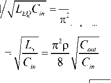
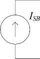
The analyzed resonant converter contains two bridge converters (an inverter and a rectifier) connected by an oscillating LCL circuit, a load and an output smoothing filter are connected to the output of the circuit (Fig. 1). The inverter generates a rectangular voltage U conv , which is applied to the input of the LCL circuit. If the frequency of the inverter conversion coincides with the resonant frequency of the circuit, a sinusoidal current I conv arises in the inductance L 1 , which coincides in phase with U conv. In this case, a current I SB is generated in the inductor L 2 , shifted relative to I inv by an angle of π/2, independent of the load. Therefore, the control signals of the rectifier are shifted relative to the control signals of the inverter by a similar angle π/2, while the rectifier voltage U rec is in phase with the current. Under the condition that the inductors L 1 = L 2 are equal, the stability of the output voltage is ensured when the load changes and the stability of the angle of shift between the choke currents L 1 and L 2 , equal to π/2 [4]. If the load resistance exceeds units of ohms, then the resonant frequency, the wave resistance of the circuit, the quality factor and the output voltage are determined by the formulas:
ю0 = 1/ LCc p = Lc
Q = 8R- πρ
u = -21
Uout 8 PISB where I SB is the input current of the converter.
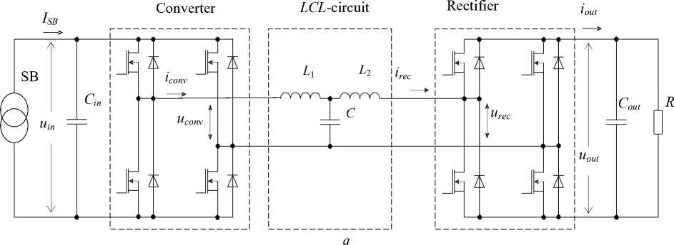
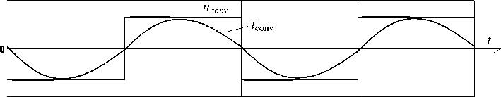
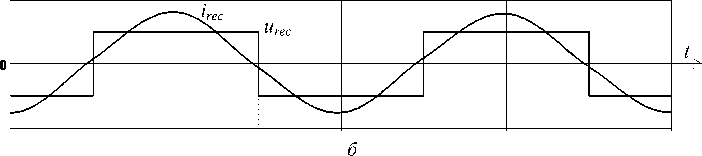
Рис. 1. Схема резонансного преобразователя энергии солнечной батареи с LCL-контуром ( а ) и диаграммы его параметров ( б )
Fig. 1. Diagram of a resonant solar battery energy converter with an LCL circuit ( a ) and diagrams of its parameters ( б )
According to formulas (1), the output voltage of the converter is determined only by the values of the supply current and the wave resistance of the oscillating circuit and does not depend on the load resistance in any way. When the converter in question is operating with a solar battery powered by a current branch, the load resistance of the converter also affects the output voltage value, since when the operating point moves within the current branch, the current decreases slightly with increasing voltage on the solar battery. However, this drop is insignificant, therefore, in further considerations, the solar battery is replaced by an ideal current source.
In steady-state mode, the output voltage does not depend on the load resistance, but an abrupt change in the latter leads to dynamic emissions determined by the circuit parameters. In [18], a mathematical model was developed that makes it possible to give qualitative and quantitative estimates of the dynamics of the circuit in question and relate them to the circuit parameters when the conversion frequency and the natural frequency of the LCL circuit are equal.
According to this model, the converter can be represented as an equivalent low-frequency oscillatory circuit (Fig. 2), the parameters of which are determined by the formulas:
^P] . 1
I 8 J R
L EQ
П Р If o I Cout, REQ
-
< 8 J
ISB
c
in
2 Р 4c~c2
® OEQ
Q EQ Р EQ/REQ ^2^
С out
π 2 ρ Сin
Р э =
conv
c
in
L EQ
R EQ
Рис. 2. Эквивалентная схема преобразователя с LCL-контуром при питании от источника тока
Fig. 2. Equivalent circuit of a converter with an LCL circuit when powered by a current source
This model does not take into account changes in the current of the solar battery depending on the illumination or aging of the solar cells, since they occur much slower than transients at the start or with a stepwise change in load resistance and can be ignored.
The above model shows that in order to ensure the required quality of transients, conditions that contradict each other must be met when starting the circuit and when the load changes abruptly. Since the quality of the starting transients is quite easily ensured by smoothly starting the circuit, in the future only transients with an abrupt load change are considered.
The instantaneous value of the output voltage, related to its steady-state value, is expressed by the following formulas:
^ OEQ t
1 + 2 5 R • e 2QEQ - sh — t
J 1 - 4 Q E q +
u^ + ( t Ml + 2 5 R -® o EQ te “° EQ t
Ю 0 EQ t
1 + 2 5 R . e' ,sin " ' t
J 4Q E q + — 1
пРи Q EQ + < 1
пРи Q EQ + = 2
пРи Q EQ + > 2
yl 1 - 4 QE q + 2 Q EQ +
® 0 EQ ,
J 4 Q EQ + - 1 2 Q EQ +
® 0 EQ
where 8 R = ( R +- R —)/ R — is the relative change in the load; R —, R + are the load resistances before and after its change, respectively; Q EQ– , Q EQ+ are the Q–values of the equivalent oscillatory circuit before and after the load change, respectively.
This model shows that the only way to improve the quality of transients in this scheme is to increase the output filter capacity, but the effectiveness of this measure has not been considered in detail.
As it is known, the quality of the transition process is assessed by the maximum deviation from the nominal value and the time of the transition process. The relative value of the maximum deviation from the nominal value can be found by solving the problem of finding the extremum of the function, which is the variable part of expressions (3):
arctg 4 Q 2 С ^-1 Сin
8 U max
I Q -
i ] СГ
Q + П C out
• e
--1
where Q – , Q + are the Q–values of the LCL circuit before and after the load change, respectively.
With sufficiently large C out , dependence (4) becomes close to the inverse of the square root of C out , therefore, with increasing output capacitance, the efficiency of improving the quality of the transient decreases. In addition, it can be seen from (2) and (3) that the transition time increases proportionally out .
When calculating the converter for an output voltage of 100V at an input current of 8A and at a conversion frequency of 100 kHz to ensure the condition 8 U max< 10%, the value of Cout is hundreds of µF, and the transition time exceeds hundreds of ms.
For reasons of electromagnetic compatibility, quite strict requirements are imposed on the supply voltage of on-board space equipment for the form of transients, for example, 8 U out of < 1% during the first 5 ms and even less during the subsequent time. In this case, C out of tens of mF will be required. Capacitors of this capacity, designed for voltages of tens of volts when operating at a conversion frequency of tens of kHz, are several times larger in size and weight than the rest of the converter. In addition, it is necessary to greatly slow down the output of the converter to full power at the start – up to several seconds. Thus, increasing the value Cout is an ineffective measure to improve the quality of the converter's transients during a stepwise load change.
Additional low-frequency output RC filter for improving the transient quality of the resonant
LCL converter
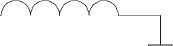
An analysis of the mathematical model represented by expressions (3–5) suggests one of the ways to improve the quality of transients of a resonant LCL converter is to filter low-frequency oscillations of the transient process using an RC circuit at the output of a circuit connected in parallel to a high–pass filter, as shown in Fig. 3, where R f and C f are respectively, the resistance and capacitance of the low-frequency filter. Computer modeling shows the high efficiency of this solution, especially for reducing the time of transients. But at the same time, it takes a considerable amount of time and does not answer the questions of how the parameters of transients depend on the values of the elements of the additional RC filter and at what values of these values the effectiveness of improving the quality of transients will be maximized. To answer these questions, it
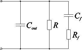
Рис. 3 Выходная цепь резонансного LCL-преобразователя при подключении низкочастотного RC-фильтра
Fig. 3. Output circuit of a resonant LCL converter when connecting a low-frequency RC filter
is necessary to analyze the proposed method, in which it is necessary to obtain a linearized equivalent of converter circuit that allows moving from computer modeling to analytical expressions.
The chain in Fig. 3 is the second order, is aperiodic, and can be characterized by the following parameters:
Q f =
T f RC f ;
D — ;
f Rf CfRC
.
\rc out^+t_ I
RC +
RCf
R f C f RC out R f C out
It is easy enough to prove that the parameter Q f cannot exceed 0.5.
The operating resistance of the chain in question can be obtained from its circuit. After being reduced to definitions (5), it has the following form:
Z f ( p ) =
-
-Rf l+ p f
2 ® f 2
® f + PQ^ + p
The expression for the transient voltage process under the influence of a stepwise change in current I f is easy to obtain from (6) using the operator method:
Uf (t ) = IR I1
к
1 + 1 - 2 ш f т f Q f
J^f
CD ft
e
7
+
1 _ 1-2^0-
к
Ш ft
e
7
An example of a transition process is shown in Fig. 4. A characteristic feature of the transition process is a rapid exponential increase at the beginning, followed by a significant slowdown. The output voltage of the rectifier has the same shape with the exception of high-frequency conversion ripples.
0 5 x 10 3 0.01 0.015 0.02
Рис. 4. Переходный процесс в выходной цепи преобразователя при воздействии единичного скачка тока при R = 12 Ом, R f = 10 Ом, С vyh = 30 мкФ, С f = 300 мкФ
Fig. 4. The transient process in the output circuit of the converter under the influence of a single current surge at R = 12 ohms, R f = 10 ohms, C out = 30 μF, C f = 300 μF
Building an operational model of a rectifier
As a result of the action of a sinusoidal current surge with a single amplitude and conversion frequency on the input of the rectifier, a rectangular voltage appears at the same input, coinciding in phase with the current, with an envelope repeating the shape of the voltage at the output of the rectifier, defined by expression (7). When replacing a rectangle with its first harmonic, the voltage at the input of the rectifier is determined by the expression:
uin = (t) = T °(t) sin («оt) uf (t) П where c( t) is the Heaviside function; co0 is the conversion frequency.
To analyze the dynamic properties, it is necessary to perform the Laplace transform from the current and voltage at the input of the rectifier, for which it is convenient to use the original multiplication theorem by a harmonic.:
u f
( x ) sin « 0 1 = U f
n П e 'u Uf (P — j «о) + e 2 Uf (P + j«о)
Taking into account expressions (6) and (9), the following expressions correspond to the current and voltage at the input of the rectifier in the operator form:
i n = ( t ) = ° ( t ) sin ( “ о t ) О I in = ( p ) = 2 «о 2
p 2 + « о 2
« 0
( P - j « 0 )( P + j « 0 )
u in = ( t ) 0 U . = ( p ) =
- 4 Rj « 2 [ 1 + ( p - j « о ) t f
|
п 2 |
« f +( p ■« Q+(p j i _ |
( p - j « о ) |
4 Rj « 2 [ 1 + ( p + j « 0 ) T f
+
+
п 2 « f + ( p + j « о ) « f + ( p + j « о ) 2 ( p + j « о ) . Q f .
;
From formulas (10), expressions of the input resistance of the rectifier in operator and frequency forms follow:
, . 4 R « 2
Z n = ( p ) = -f-f п « о
< - j [ 1 + ( p - J « о )T f ] ( p + J « о ) + j [ 1 + ( p + J « о )T f ] ( p - j « о ) > « f +( p - j « о ) « f + ( p - j « о ) 2 « f +( p + j « о )«- + ( p + j « о ) 2 Q f Q f
After reducing to a common denominator, it can be seen that the operating resistance of the rectifier loaded on the output filter in question is of the fourth order. Graphs of the resistance modulus in frequency form indicate its resonant character (Fig. 5).
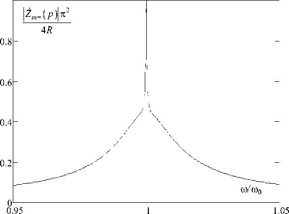
Рис. 5. Модуль частотного сопротивления выпрямителя at R = 12 ohms, R f = 10 ohms, C out = 30 μF, C f = 300 μF
Fig. 5. The frequency resistance module of the rectifier at R = 12 ohms, R f = 10 ohms, C out = 30 μF, C f = 300 μF
Analysis of the dynamic properties of the converter when powered by a constant voltage source
It is possible to analyze the dynamics of an LCL circuit by determining its response to a sinusoidal voltage surge. Input current and load voltage should be considered as responses. The transfer functions are easy to determine from its equivalent scheme shown in Fig. 6. The dynamic properties of the converter easily follow from the dynamics of the LCL circuit by eliminating fluctuations at the conversion frequency.
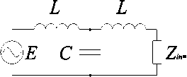
Рис. 6. Эквивалентная схема LCL-контура, нагруженного на выпрямитель, при питании от источника напряжения
Fig. 6. Equivalent circuit of an LCL circuit loaded on a rectifier when powered by a voltage source
The transfer functions can easily be expressed in terms of the operator resistance of the circuit:
Z ( ) L + PL + Z i n = ( P ) PL ( 2 + P2LC ) + Z i n = ( P ) ( P2LC + 1 )
cir^’ P 1 + [ PL + Z i n = ( P ) ] PC 1 + P 2 LC + PCZ i n = ( P )
The transfer function for finding the input current of a circuit is its input conductivity:
G cir ( P ) =
1 = 1 + P2 LC + PCZ i n = ( P )
Z cr ( P ) PL ( 2 + P2LC ) + Z i „ = ( P )( P2LC + 1 )
Voltage transfer function:
Zcr (P)- PL Zin — ( P) _ Zin — ( P)
------: :—: •--------:—:----------—------7----------------:------------------7---------------г.
Zcr (P) Zin — (P) + PL pL (2 + P2LC) + Zn — (P)(P2LC +1)
The images of the input current of the circuit and the voltage at the input of the rectifier when applying a sinusoid surge in the operator form are determined by the following expressions:
I1 ( s )— ZZ „ ( P )( P 2 + 1 )
• / x K ( P ) U-t ( P )— P 27 1
Taking into account expression (11), it follows that the obtained transfer functions are of the sixth order, which makes it much more difficult to find the contour response. Due to the high order of the resulting expressions and the resonant nature of the system under consideration, as well as the fact that it is ultimately necessary to investigate the dynamic voltages and currents at the input and output of the converter, it is advisable to use the low-frequency equivalent method, which is used to analyze complex oscillatory systems, to find responses. In this case, instead of the transfer functions of the entire oscillatory system, transfer functions for complex envelopes of input and output signals are considered, which reduces the order of expressions for describing the system.
After the necessary transformations, the following expression of the transfer function for the complex voltage envelope is obtained in operator form:
K LF ( P y— ji^ f
» f + p Q + p 2
To obtain the complex voltage envelope at the input of the rectifier when a sine is applied to the input of the circuit, it is necessary to take the inverse Laplace transform from the product (16) by j / p. The voltage at the output of the rectifier differs from the complex voltage envelope at its input only by a factor of π/4, therefore, after all the necessary transformations, it is determined by the following expression:
U ou. ( ‘ H Q i 1
r1 +
1 - 2 » , ; Q
J-4, ,
e
+
r
1 -
-
1 - 2 Ш , T , Q , ]1 - 4 Q, ,
f- [ 1+, \ 1 - 4 Q 2 ]
-
2 Q , I v J
^ (17)
Transfer function for the complex envelope of the circuit current in operator form:
G LF ( p ) —
j Q Ю 2 ( 1 + p T , )
P 2 ®/ 2
® f + P7 f + P Qf
The resulting expression differs from (16) only by a factor of 1/ p , and the modulus of the complex envelope of the circuit current differs from the inverter current by a factor of 2/ n , so in the end, after appropriate calculations, the following expression for the inverter current is obtained:
2Q conv
п р
1 - -
Г
1 + 1 - 2 ^ f т Q
Ш f t
e
+
( ,
1 - 1 - 2 ^ f т f Q f
e - f ( 1 + )
\ (19)
к
7
к
7
The time-dependent parts of expressions (17) and (19) contain the parameters of the output filter, and the contour parameters act only as a proportionality coefficient, which means that the inertial properties of the input and output of the converter do not depend on the parameters of the oscillatory circuit and are determined only by the elements of the output filter, which is explained by the fact that the filter time constant is much more greater than the constant rise time of the circuit current.
Synthesis of an equivalent converter circuit
A comparison of expressions (17) and (19) shows that the inverter current and the rectifier output voltage are related by a simple expression that matches the static transmission function of the converter:
п2р uout ( t)= 8 iconv ( t)
The resulting expression suggests that the inverter can be represented as a circuit that is qualitatively a dual circuit with respect to the output circuit. In [18], when analyzing a converter without a filter, exactly this result was obtained. The inverter was presented in the form of a circuit representing a serial connection of resistance and capacitance, which is qualitatively a dual circuit with respect to the output filter, which is a parallel connection of load resistance and high-frequency pulsation suppression capacity. If there is a low-pass filter in the output circuit, the equivalent inverter circuit should be a series resistance of the equivalent elements L EQ and R EQ found earlier, with parallel connection of the elements L FE and R FE , as shown in Fig. 7.
In this case, the operator resistance can be represented by the following expression:
Z conv ( p ) = R EQ
1 + f L EQ- + L FE- + LфЭ ^ p + к Req Rfe Req J?
LEQLFE 2
REQRFE
1 + '" p
RFE
On the other hand, the input operating resistance of the inverter can be found from the image of the inverter current, which is the response to a single voltage surge, which follows from (18), taking into account the rectification and replacement of the rectangular voltage at the output of the inverter by its first harmonic, and taking into account (5) is determined by the expression:
Z conv ( p )
Пр 1j + PRC ut+ R f C 1+ RCjyR^ 8 Q 1 + pRfCf
If we compare expressions (21) and (22), we can obtain expressions for the elements of an equivalent inverter circuit:
R =ПР
EQ 8 Q 1
n p
к
1 R
LEQ
DRCout ^ LEQ
REQ
L E = rc. ^ lfe = ф FE
RFE
L FE = R C ^ R = f f FE
RFE
к_р к 8
к_р к 8
^п2р
I C ut
I C f
к 8 J R f
It should be noted that the values of L EQ and R EQ will be the same as in the case of analyzing the converter without an additional low-pass filter, which confirms the correctness of the equivalent inverter circuit.
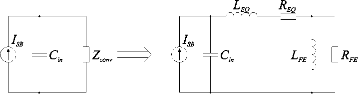
Рис. 7. Эквивалентная схема преобразователя с LCL-контуром при питании от источника тока
Fig. 7. Equivalent circuit of a converter with an LCL circuit when powered by a current source
Verification of the obtained results by computer simulation
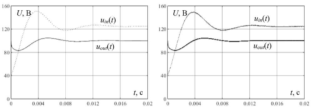
To verify the results obtained, a model containing the initial converter circuit and its equivalent circuit was built in the Matlab Simulink 2022b simulation software. Examples of voltage transients at the inputs and outputs of the converter and its equivalent circuit when changing the load resistance from 30 to 10 ohms and vice versa, shown in Fig. 8 and 9, respectively, are given at the following values of the converter circuit elements: input current I SB = 8A, conversion frequency f = 100 kHz, nominal output voltage output voltage U out = 100V, input filter capacity C out = 30pF, high-pass output filter capacity C out = 30pF, low-pass output filter capacity C f = 270pF, low-pass filter resistance R f = 2 ohms. It is necessary to note the high degree of coincidence, which indicates the validity of the conclusion about the insignificant influence of the oscillatory circuit on the dynamics of the converter.
The obtained equivalent scheme allows for the analysis of transient processes occurring in the converter by solving the corresponding differential equations. The solution of these equations is complicated by the 3rd order of the system and the cumbersome expressions. At the time of writing the article, solutions in the form of relatively simple expressions that clearly reflect the properties of the equivalent scheme have not been obtained. However, using an equivalent circuit, it was possible to significantly simplify and speed up computer simulation of converter transients without taking into account high-frequency output voltage ripples. The construction time of transients for the initial circuit is several minutes, for the equivalent circuit it is several seconds, i.e. the simulation speed has increased by about 60 times.
а б
Рис. 8. Переходные процессы при изменении сопротивления нагрузки преобразователя с 30 до 10 Ом: а – для эквивалентной схемы преобразователя; б – для преобразователя
Fig. 8. Transients when the load resistance of the converter changes from 30 to 10 ohms: а – for the equivalent converter circuit; б – for the converter
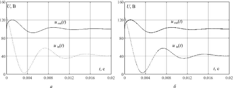
Рис. 9. Переходные процессы при изменении сопротивления нагрузки преобразователя с 10 до 30 Ом: а – для эквивалентной схемы преобразователя; б – для преобразователя
Fig. 9. Transients when the load resistance of the converter changes from 10 to 30 ohms: а – for the equivalent converter circuit; б – for the converter
To compare the effect of using high-frequency and low-frequency filters, the characteristics were removed when changing the load resistance from 10 to 30 ohms for the following values of the converter circuit elements: input current I SB = 8A, nominal output voltage U out = 100V, input filter capacity Cin = 30μF, high-frequency output filter capacity Cout = 30μF, low-pass output filter capacity C f = 270μF. The comparison was performed at one value of the low-pass filter capacity and zero and non-zero values of R f . At R f = 0, the converter corresponds to the scheme in Fig. 1 with a total output filter capacity equal to the sum of C out and C f , i.e. 300μF. The results are shown in Fig. 10. It can be seen that the presence of a nonzero R f significantly reduces the time of transients.
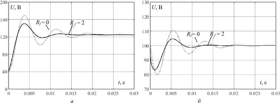
Рис. 10. Переходные процессы при изменении сопротивления нагрузки преобразователя с 10 до 30 Ом и разных значениях R f : а – для входного напряжения; б – для выходного напряжения
Fig. 10. Transients when the load resistance of the converter changes from 10 to 30 ohms and different values of R f : a – for the input voltage; б – for the output voltage
During the simulation, the following patterns were also noticed:
-
1. The amplitude of the input voltage overshoot decreases with increasing values of C f and R f . But at the same time, as C f increases, the time of transients increases, while an increase in the value of R f affects them in the opposite way.
-
2. To achieve maximum effect, the capacitance values of high-frequency capacitors should be minimal, determined only by the required level of high-frequency pulsations.
-
3. There is a value R f at which the magnitude of the output voltage surge during load change is minimal, but at the same time it is less than the same indicator at R f = 0 by no more than 20 %.
Thus, the amplitude of the output voltage surge during load change is still determined by the output filter capacity. However, it should be noted that the serial connection of resistance and capacitance is one of the variants of the equivalent circuit of a low-frequency capacitor, which, compared with a high-frequency capacitor, all other things being equal, has much lower weight and dimensions.
Conclusion
-
1. Despite the nonlinearity of the resonant transducer due to the presence of key elements, its dynamic properties can be described using a linear mathematical model. Due to the fact that the transient time of the output filter is at least an order of magnitude longer than that of the oscillatory circuit, it can be assumed that the dynamic properties of the converter are determined only by its filter circuits at the input and output.
-
2. It has been found that, from the point of view of the dynamics of the input and output parameters, a resonant LCL converter with constant voltage supply can be replaced by an equivalent circuit that is dual to the output filter. When the converter is powered from a DC source, an input capacitive filter is added to the equivalent circuit and the converter can be considered as an equivalent oscillatory circuit. A similar result was obtained in [18]. By replacing the converter with an equivalent oscillatory circuit, a mathematical model was obtained that does not take into account high-frequency pulsations, with the help of which it was possible to increase the speed of computer modeling several tens of times and investigate the transients of input and output voltages.
-
3. It has been found that the use of an additional low-frequency output filter with an abrupt load change significantly reduces the time of input and output voltage transients, significantly reduces the
amplitude of the input voltage transition process, and also improves the mass and size parameters of the converter.
Bibliographic references
-
1. Милях А. Н., Кубышин Б. Е., Волков И. В. Индуктивно-емкостные преобразователи источников напряжения в источники тока. Киев : Наукова думка, 1964. 320 с.
-
2. Borage M., Tiwari S., Kotaiah S. Analysis and design of LCL-T resonant converter as a constant-current power supply // IEEE Transactions on Industrial Electronics. 2005. Vol. 52, No. 6. P. 1547–1554.
-
3. Разработка систем заряда емкостных накопителей энергии / Ю. И. Болотовский, Г. И. Та-назлы, Е. И. Вашкевич, А. В. Никитин // Силовая электроника. 2008. № 18. С. 49–56.
-
4. LCL-T resonant converter based on dual active bridge topology in solar energy applications / A. V. Osipov, Y. A. Shinyakov, V. N. Shkolniy, M. S. Sakharov // Journal of Aerospace Technologies and Management. 2017. Vol. 9, No. 2. P. 257–263.
-
5. Осипов А. В. Энергетически эффективные режимы работы преобразователя частоты с последовательно-параллельным резонансным контуром при стабилизации мощности на переменной нагрузке // Электротехника. 2017. № 6. С. 70–76.
-
6. Zouggar S., Charif H. N., Azizi M. Neural control and transient analysis of the LCL-type resonant converter // The European Physical Journal Applied Physics. 2000. Vol. 11, No 1. P. 21–27.
-
7. Borage M., Tiwari S. AC analysis of resonant converters using PSpice – a quicker approach // Asian Power Electronics Journal. 2012. Vol. 6, No 2. P. 1–6.
-
8. Analysis, design, modeling and control of an interleaved-boost full-bridge three-port converter for hybrid renewable energy systems / M. C. Mira, Z. Zhang, A. Knott, M. A. E. Andersen // IEEE Transactions on Power Electronics. 2017. Vol. 32. P. 1138–1155.
-
9. Dieckerhoff S., Ryan M. J., De Doncker R. W. Design of an IGBT-based LCL-resonant inverter for high-frequency induction heating // Conference Record of the 1999 IEEE Industry Applications Conference. Thirty-forth IAS Annual Meeting, 3–7 October 1999, Phoenix, AZ, USA. Phoenix, 1999. Vol. 3. P. 2039–2045.
-
10. Wei Y., Luo Q., Mantooth H. A. An LLC and LCL-T Resonant Tanks Based Topology for Battery Charger Application // CPSS transactions on power electronics and applications. 2021. Vol. 6, No. 4. P. 263–275.
-
11. Bayoumi E. Design and control of an LCL series parallel resonant converters using bacterial foraging optimization // International Journal of Power Electronics. 2012. Vol. 4, No. 5. P. 479–503.
-
12. Design of LCL-T Resonant Converter Including the Effect of Transformer Winding Capacitance / M. Borage, K. V. Nagesh, M. S. Bhatia, S. Tiwari // IEEE Transactions on Industrial Electronics. 2009. Vol. 56, No. 5. P. 1420–1427.
-
13. Reddy V. B., Bhaskar M. S., Subramaniam U. Resonant DC/DC Converters: Investigating Phase-Shift Control // Energies. 2023. Vol. 16. P. 6012.
-
14. Design and Implementation of a Wireless Power Transfer System Using LCL Coupling Network with Inherent Constant-Current and Constant-Voltage Output for Battery Charging / P. Nie, S. Xu , Z. Wang, S. Hashimoto, L. Sun, T. Kawaguchi // Energies. 2025. Vol. 18. P. 341.
-
15. Nagarajana C., Madheswaranb M. Experimental Study and Comparative Analysis of CLL-T and LCL-T Series Parallel Resonant Converter with Fuzzy/PID Controller // Journal of Electrical Engineering. 2011. Vol. 11. P 121–129.
-
16. Chandrasekhar P., Reddy S. R. Design of LCL resonant converter for electrolyser // The Annals of “Dunarea de Jos” University of Galati Fascicle III. 2010. Vol. 33, No. 1. P. 5–11.
-
17. Wang S., Fang W., Li R. Research on High Power Charging Power Supply Based on LLC and LCL-T Resonant Converter // Journal of Physics: Conference Series. 2023. Vol. 2625. P. 0120216.
-
18. Сахаров, М. С., Осипов А. В. Динамическая модель резонансного преобразователя с Т-образным контуром // Научный вестник НГТУ. 2017. № 4. С. 47–66.
-
19. Fang X. Analysis and design optimization of resonant DC-DC converters: doctoral dissertation / University of Central Florida. Orlando, FL, 2012. 190 p.
-
20. Analysis of CLL voltage-output resonant converters using describing functions / M. P. Foster, C. R. Gould, A. J. Gilbert, D. A. Stone, C. M. Bingham // IEEE Transactions on Power Electronics. 2008. Vol. 23. P. 1772–1781.
-
21. Joung M., Kim H., Baek J. Dynamic analysis and optimal design of high efficiency full bridge LLC resonant converter for server power system // Twenty-Seventh Annual IEEE Applied Power Electronics Conference and Exposition (APEC), Orlando, Florida, 5–9 February 2012. Orlando, 2012. P. 1292–1297.
-
22. Manli Hu. Modeling, optimization and control design for LCC resonant converter applied in very low frequency high voltage generator: doctoral dissertation / Paderborn University. Paderborn, 2014. 192 p.
-
23. Павлов Г. В., Обрубов А. В., Никитина Е. В. Динамическая модель резонансного преобразователя постоянного напряжения с фазовым регулированием // Електронний вісник НУК. 2010. № 3. C. 47–66.
-
24. Выбор корректирующего звена резонансного преобразователя на основе экспериментальной АЧХ по управляющему воздействию / Р. Г. Калинин, А. В. Кобзев, В. Д. Семенов, В. А. Федотов // Доклады ТУСУР. 2013. Т. 4, № 30. С. 91–95.
-
25. Шарыгин В. А., Семенов В. Д., Кабиров В. А. Однотактный резонансный преобразователь с частотным управлением // Электронные средства и системы управления : XIV Междунар. науч.-практ. конф., 28–30 ноября 2018 г. Томск : Томск. гос. ун-т систем упр. и радиоэлектроники. 2018. С. 186–191.
-
26. Столярова А. А., Михальченко С. Г., Апасов В. И. Математическая модель резонансного LLC-преобразователя // Доклады ТУСУР. 2020. Т. 23, № 3. С. 86–91.
-
27. Белов, Г. А. Анализ режимов преобразователя постоянного напряжения с последовательным резонансным инвертором при прерывистом токе в контуре // Практическая силовая электроника. 2016. Т. 1, № 61. С. 29–38.
-
28. Расчет и моделирование переходных процессов в резонансном преобразователе постоянного напряжения типа LLC / Г. А. Белов, Г. В. Малинин, Л. С. Севриков, Ю. М. Семенов // Электротехника. 2020. № 8. С. 23–30.
-
29. Белов Г. А., Серебрянников А. В., Павлова А. А. Расчет и моделирование переходных процессов в резонансном преобразователе с простым последовательным колебательным контуром // Практическая силовая электроника. 2020. Т. 2, № 78. С. 9–16.
-
30. Gautam K., Chatterjee A. A Variable Frequency CC-CV Charging for Electric Vehicles with CLCL Resonant Converter // IFAC-PapersOnLine. 2024. Vol. 50, Is. 2. P. 131–136.
-
31. Ray A., Kaushik R. Design and Evaluation of a High Current Gain Resonant Inverter for Subsea Electrical Heating // IEEE Transactions on Industry Applications. 2022. Vol. 58, Is. 4. P. 5093– 5103.
