The utility model relates to a three-stage series LNG cold energy power generation system for recovering flue gas waste heat

Author: Chen Zh., Kuznetsov D., Yang X.
Journal: Бюллетень науки и практики @bulletennauki
Section: Технические науки
Article in issue: 6 т.10, 2024.
Free access
In this paper, a three-stage series power generation system is designed. The waste heat generated by the engine is used as the heat source, and the energy released before LNG liquefaction is used as the cold energy. It is used to improve the performance of the system by increasing the carbon dioxide transcritical cycle. With the target of maximum generation capacity and exergic efficiency, exergic pressure and condensation pressure in the system were selected for the most beneficial generation capacity and efficiency of the system through analysis of exergic pressure and evaporation pressure.
Three-stage series, lng, waste heat, generation capacity, exergic efficiency
Short address: https://sciup.org/14130490
IDR: 14130490 | UDC: 621 | DOI: 10.33619/2414-2948/103/37
Трехступенчатая последовательная LNG-система выработки энергии на переработку остатков тепла от дыма
В данной статье разработана трехступенчатая серия энергогенерирующих систем. Отработанное тепло, получаемое двигателем, используется в качестве источника тепла, а энергия, высвобождаемая до сжижения СПГ, используется в качестве холодной энергии. Он используется для повышения эффективности системы путем увеличения транскритического цикла диоксида углерода. С целью достижения максимальной выработки электроэнергии и повышения эффективности использования энергии в качестве целевых показателей для наиболее выгодных генерирующих мощностей и повышения эффективности были выбраны показатели давления испарения и конденсации в системе.
Text of the scientific article The utility model relates to a three-stage series LNG cold energy power generation system for recovering flue gas waste heat
Бюллетень науки и практики / Bulletin of Science and Practice
UDC 621
LNG, known for its cleaner burning characteristics compared to conventional hydrocarbon fuels, has become a viable alternative in the energy landscape [1]. However, the process of
(ос) CD liquefying natural gas results in the production of extremely low temperatures, generating a substantial amount of cold energy [2]. Rather than considering this cold energy as a byproduct, it has become increasingly clear that harnessing its potential can lead to significant energy savings and enhanced system efficiency. By constructing power generation systems that utilize the cold energy of LNG, we can unlock various opportunities for energy recovery and utilization. The concept involves using the cold energy to drive innovative cooling technologies, such as Organic Rankine Cycles (ORCs) [3] or absorption refrigeration systems. These systems can generate electricity or provide cooling for industrial processes, reducing the overall energy consumption and environmental footprint.
Additionally, the waste heat generated by engine flue gases presents yet another valuable energy stream that can be effectively harnessed [4]. Internal combustion engines, widely used in power generation and transportation, emit significant amounts of waste heat through their exhaust gases. Rather than allowing this waste heat to dissipate into the environment, capturing and utilizing it can lead to substantial energy savings and increased system efficiency. The construction of power generation systems that incorporate waste heat recovery from engine flue gases opens up a realm of possibilities. By implementing heat recovery technologies, such as heat exchangers or steam turbines, the waste heat can be transformed into useful energy for electricity generation or other industrial processes. This approach, known as combined heat and power (CHP) or cogeneration, allows for the simultaneous production of electricity and thermal energy, maximizing the overall energy utilization and reducing greenhouse gas emissions.
In conclusion, the construction of power generation systems that harness the cold energy of LNG and the waste heat from engine flue gases offers tremendous potential for energy optimization and sustainability. By capitalizing on these previously untapped energy sources, we can enhance energy efficiency, reduce reliance on conventional fuels, and contribute to a cleaner and more sustainable future. In this paper, a three-stage series power generation system is developed to make full use of LNG cold energy and flue gas waste heat. The use of ethane and carbon dioxide as the working medium, in particular, the use of carbon dioxide as the working medium is designed to build a cross-critical cycle to improve system performance. Then, taking net power generation and exergic efficiency as targets, the condensation pressure and evaporation pressure in the system were analyzed. Finally, the values of condensation pressure and evaporation pressure that can increase these two targets are selected.
System model and calculation method
The structure of the system is shown in Figure 1. We can clearly see that the system is composed of four parts, namely the LNG part and three cycles.
Part 1: LNG1 is the LNG in the initial state of the LNG storage tank, which is extracted by pump 0 into LNG2, which enters the heat exchanger HX1 to provide cold energy for the cooling of cycle 1, and at the same time, LNG2 is heated into LNG3, which enters the heat exchanger HX5 and is heated by flue gas EG3 to the usable temperature LNG4.
Cycle 1: Point 1 enters the pump 1 is pressurized to become point 2, point 2 enters the heat exchanger HX2 is heated to point 3, point 3 enters the turbine 1 to compress and do work to point 4, point 4 enters HX1 is cooled to point 1 and then enters the next cycle.
Cycle 2: Point 5 enters the pump 2 and is pressurized to become point 6, point 6 enters the heat exchanger HX3 is heated to point 7, point 7 enters the turbine 2 to compress and do work to point 8, point 8 enters HX2 is cooled to point 5 and then enters the next cycle.
Cycle 3: Point 9 enters the pump 3 becomes point 10 after pressurization, point 10 enters the heat exchanger HX4 is heated to point 11, point 11 enters the turbine 3 to compress and do work to point 12, point 12 enters HX3 is cooled to point 9 and then enters the next cycle.
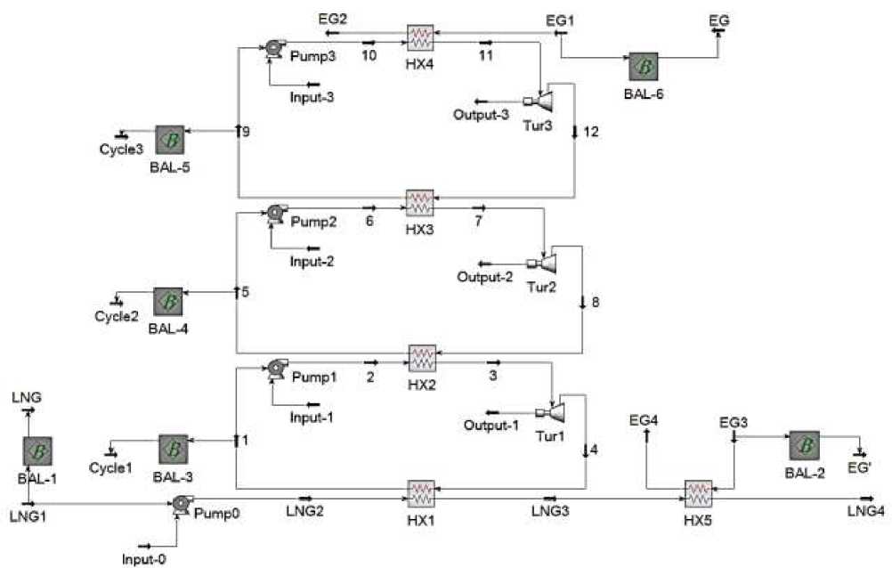
Figure 1. System model diagram
The working medium selected in this system is carbon dioxide and ethane respectively, in which ethane is used as the working medium in cycle 1 and cycle 2, and carbon dioxide is used as the working medium in cycle 3. The reason for choosing ethane [5] is that it is flammable and nontoxic, has little impact on the environment, zero ODP, and very low GWP [6]. It is well known that they are suitable for extremely low temperature applications and have good thermodynamic properties. Carbon dioxide is chosen to build a transcritical cycle, which is designed to meet the high temperature conditions of the flue gas. The boundary conditions [7] of the system are shown in Table 1:
Table1
BOUNDARY CONDITIONS FOR THE SYSTEM
|
LNG |
Composition |
Methane |
|
Mass flow rate, (kg/s) |
0.61 |
|
|
Inlet pressure, (kPa) |
100 |
|
|
Outlet pressure, (kPa) |
592 |
|
|
Inlet temperature, (◦C) |
-162 |
|
|
Outlet temperature, (◦C) |
0 |
|
|
EG |
Composition,(mass fraction, %) |
N2(73.85),CO2(10.48),H2O(8.25),O2(7.42) |
|
mass flow rate, (kg/s) |
18.9 |
|
|
inlet temperature, (◦C) |
230 |
|
|
outlet temperature, (◦C) |
100 |
|
In order to accurately evaluate the thermodynamic performance of the system, a thermodynamic model is constructed and analyzed in terms of quantity and mass of energy conversion according to the first and second laws of thermodynamics. During the analysis, each component of the system is treated as an independent control volume, following the mass conservation equation and the energy conservation equation, which are as follows:
Emin Emout
SQin + Z(mh)in = XQout + XmVout + ™ among them, h represents the specific enthalpy of the working medium, Q represents the heat transfer, m represents the mass flow rate, and W represents the power. The subscripts in and out indicate the incoming and outgoing respectively, while the kinetic energy and potential energy can be ignored.
Exergy (Ex) is defined as the maximum output work that can be achieved when the working medium reversibly changes from its current temperature and pressure to a reference state. In this study, we focus on enthalpy exergy, as defined in equation (3). Since this study deals with real processes, which are usually irreversible, this results in Exergy loss, which is defined in equation (4):
Ex = m[(h-h0)-T0(s-s0)] (3)
ДЕх = £Ехы-EEX out (4)
where, T0 is the reference temperature, h0 and s0 respectively represent the specific enthalpy and specific entropy of the working medium in the reference state. The reference temperature and pressure were set at 298 K and 0.1 MPa.
Exergic damage of each heat exchanger is calculated as follows:
^ExHX1 = ExLNG2 + Ex4 - (ExLNG3 + Exi)
^ExHX2 = Ex2 + Ex4 - (Ex8 + Ex5)
^ExHx3 = Ex12 + Ex6 - (Ex9 + Ex7)
№xhx4 = ExEGi + Exi0 - (ExEG2 + Exn)
^ExHX5 = ExLNG3 + ExEG3 - (ExLNG4 + ExEG4)
Exergic damage of each pump is calculated as follows:
WpumpO = mLNG1(hLNG2 - hLNG1)
^ExpumpO ExLNG2 + ^PumpO ExLNG1(H)
Wpump1 = m1(h2 -h1)
^EXpump1 = EX2 + Wpump1 - EX1
Wpump2 = m5(h6 -hs)
^ExPump2 Ex6 + Wpump2 Ex5O
Бюллетень науки и практики / Bulletin of Science and Practice Т. 10. №6. 2024
|
ШРитр3 m9(h10 h9) |
(16) |
|
Л ЕхРитр3 Ех10 + ШРитр3 Ех9 |
(17) |
Exergic damage of each turbine is calculated as follows:
|
Ш тиг1 = m 3( h 3 - h 4) |
(18) |
|
ЛЕхТиг1 = Ех3 + Штиг1 - Ех4 |
(19) |
WTur2 = m7(h7-h8)(20)
ЛЕ хтиг2 = Ex7 + Штиг2 - Е x8
Штигз = m^Chu - h^
ЛЕхтигз = Ехц + Штигз -Eq2
The net output power of system Wnet :
Wnet = ШТиг1 + ШТиг2 + ШТиг3 - (ШРитр0+ШРитр1 + ШРитр2 + ШРитр3)
Exergy efficiency of the system:
=Щпес(25)
еХ (ExEG1 — ExEG2) + (ExEG3 — ExEG4 ) + ( ExLNG1 — ExLNG4 )
Results and discussion
When the initial system was built, the only goal was to make the system run normally, and the exergic efficiency of the system was not considered in which case the generation capacity and exergic efficiency of the system were superior. The initial system parameters are shown in Table 2.
INITIAL PARAMETERS
Table 2
|
State |
Temperature (°C) |
Pressure (kPa) |
Stream flow (kg/h) |
Enthalpy (kJ/kg) |
Entropy(kJ/(kg- C |
|
LNG1 |
-162.00 |
100 |
2196.00 |
-5580.47 |
4.75 |
|
LNG2 |
-161.80 |
592 |
2196.00 |
-5579.10 |
4.75 |
|
LNG3 |
-75.00 |
592 |
2196.00 |
-4895.95 |
9.61 |
|
LNG4 |
0.00 |
592 |
2196.00 |
-4731.74 |
10.31 |
|
1 |
-91.09 |
100 |
2482.50 |
-3486.82 |
3.82 |
|
2 |
-90.65 |
500 |
2482.50 |
-3485.95 |
3.82 |
|
3 |
50.00 |
500 |
2482.50 |
-2777.39 |
6.92 |
|
4 |
-14.43 |
100 |
2482.50 |
-2882.51 |
6.99 |
|
5 |
-34.14 |
1000 |
2898.19 |
-3339.39 |
4.51 |
|
6 |
-33.20 |
2000 |
2898.19 |
-3336.86 |
4.51 |
|
7 |
110.00 |
2000 |
2898.19 |
-2677.12 |
6.85 |
|
8 |
77.08 |
1000 |
2898.19 |
-2732.46 |
6.87 |
|
9 |
26.66 |
7000 |
6377.12 |
-9163.09 |
2.49 |
|
10 |
45.92 |
15000 |
6377.12 |
-9148.58 |
2.50 |
|
11 |
225.00 |
15000 |
6377.12 |
-8812.57 |
3.37 |
|
12 |
156.50 |
7000 |
6377.12 |
-8863.26 |
3.39 |
|
State |
Temperature (°C) |
Pressure (kPa) |
Stream flow (kg/h) |
Enthalpy (kJ/kg) |
Entropy(kJ/(kg^ °C) |
|
EG1 |
230.00 |
100 |
17249.77 |
-1879.34 |
6.04 |
|
EG2 |
100.00 |
100 |
17249.77 |
-2020.57 |
5.72 |
|
EG3 |
230.00 |
100 |
2553.27 |
-1879.34 |
6.04 |
|
EG4 |
100.00 |
100 |
2553.27 |
-2020.57 |
5.72 |
At the same time, in order to analyze the thermodynamic performance and economy of the system, this study made the following assumptions before constructing the simulation model with APSPEN HYSYS:
-
1. The whole system operates under steady state conditions;
-
2. Ignore the heat loss and pressure drop of all heat exchangers;
-
3. The host involved in the study is running at 100% load;
-
4. The isentropic efficiency of the pump and expansion machine is set at 85% [8], and the power generation efficiency is set at 100%;
-
5. The ambient temperature is 250C, and the ambient pressure is 0.1MPa [4];
-
6. The heat transfer coefficient of evaporator is 2kW/(m2·K), and the heat transfer coefficient of condenser is 1.5kW/(m2·K) [9, 10];
-
7. The supercooling degree of the outer cycle and the inner cycle is set at 20C [11];
-
8. LNG, outer circulating working medium, inner circulating working medium and flue gas all use P-R equation as state equation;
-
9. During the operation of the system, no chemical reaction will occur in the working medium;
-
10. The minimum pinch point temperature difference of the heat exchanger is 50C [12], while the pinch point temperature difference of the evaporator is maintained at 50C.
After calculation from the parameters in Table 2, we can get that the net power generation W net of the system is 177.7 kW, while the EXergic efficiency η ex is 24.93%.
The condensing pressure and evaporation pressure of the system are shown in Figure 2, 3 and 4. We can clearly see that the net generation capacity of the system and the exergic efficiency of the system change in the same trend with different pressures. That is, the net generation capacity and exergic efficiency of the system are negatively correlated with condensation pressure and positively correlated with evaporation pressure. As a result, exergic efficiency of the system can be enhanced by lowering condensation pressure or increasing evaporation pressure.
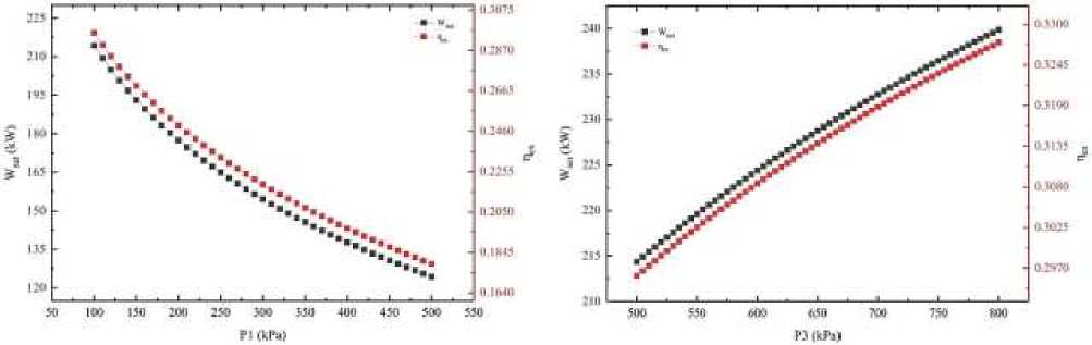
Figure 2. Condensing pressure and evaporation pressure of cycle 1
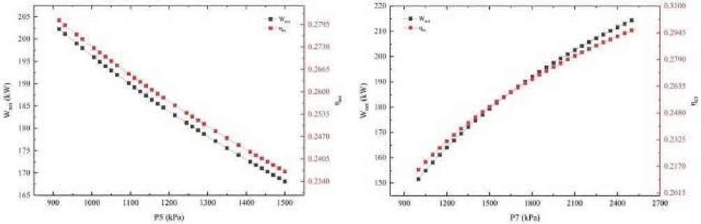
Figure 3. Condensing pressure and evaporation pressure of cycle 2
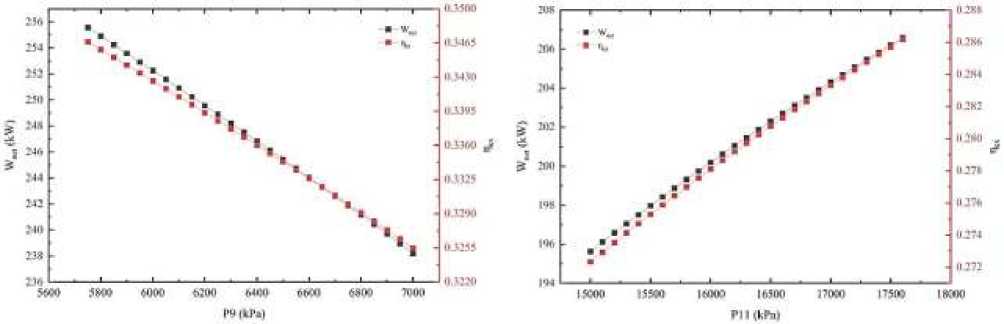
Figure 4. Condensing pressure and evaporation pressure of cycle 3
At the same time, certain restrictions will narrow the scope of variable selection and make it easier to obtain more appropriate parameters.
-
1. The pressure of the system must be greater than 0.1 MPa atmospheric pressure;
-
2. The condensing pressure of the system must be less than the evaporation pressure of the system;
-
3. The critical pressure of carbon dioxide in the third cycle is 7300 kPa, so the condensing pressure in the third cycle should be less than 7300kPa, and the evaporation pressure should be greater than 7300kPa.
The final system parameters are shown in Table 3. By comparison with the initial parameters, since the condensing pressure of the first cycle of the initial system is 100 kPa, which is already the lowest, we increased the evaporation pressure of the first cycle from 500 kPa to 800kPa. We reduced the condensing pressure of the second cycle by 50 kPa and increased the evaporation pressure by 500 kpa. We reduced the condensing pressure in the third cycle by 1250 kPa and increased the evaporation pressure by 5000kPa. After calculation, the net power generation of the final optimized system was 259.2kW, while the exergic efficiency was 35.1%, which was a great increase compared with the initial system. Net power generation increased by 45.86%, while exergic efficiency increased by 10.17%.
Бюллетень науки и практики / Bulletin of Science and Practice Т. 10. №6. 2024 FINAL PARAMETERS Table 3 State Temperature (°C) Pressure (kPa) Stream flow (kg/h) Enthalpy (kJ/kg) Entropy(kJ/(kg• °C) LNG1 -162.00 100 2196.00 -5580.47 4.75 LNG2 -161.80 592 2196.00 -5579.10 4.75 LNG3 -75.00 592 2196.00 -4895.95 9.61 LNG4 0.00 592 2196.00 -4731.74 10.31 1 -91.09 100 2608.48 -3486.82 3.82 2 -90.65 800 2608.48 -3485.31 3.82 3 50.00 800 2608.48 -2782.85 6.78 4 -32.78 100 2608.48 -2911.69 6.88 5 -35.80 950 3130.52 -3344.24 4.49 6 -34.38 2500 3130.52 -3340.35 4.49 7 110.00 2500 3130.52 -2684.34 6.77 8 63.56 950 3130.52 -2758.93 6.81 9 18.18 5750 6962.47 -9198.09 2.37 10 40.97 20000 6962.47 -9176.96 2.38 11 225.00 20000 6962.47 -8827.04 3.29 12 115.30 5750 6962.47 -8903.13 3.32 EG1 230.00 100 17249.77 -1879.34 6.04 EG2 100.00 100 17249.77 -2020.57 5.72 EG3 230.00 100 2553.27 -1879.34 6.04 EG4 100.00 100 2553.27 -2020.57 5.72
Conclusion
In this paper, a three-stage series power generation system is designed for the waste heat utilization of engine flue gas. The system combines LNG cold energy with engine flue gas waste heat to achieve efficient use of energy. Through analyzing the evaporation pressure and condensation pressure of the three sub-cycles for the net generation capacity and exergic efficiency, the exergic pressure which has a more beneficial impact on the system performance is selected. We can see from the comparison that the condensation pressure and evaporation pressure selected after the analysis, the net power generation of the system increased by 45.86%, while the exergic efficiency increased by 10.17%.
In conclusion, the system designed in this study shows the characteristics of high efficiency, energy saving and environmental protection, which provides a valuable reference for the follow-up research. Future studies may explore the applicability of different algorithms in the utilization of cold and heat energy of LNG ships, and conduct dynamic simulation of the system to improve its practicability in engineering applications.
References The utility model relates to a three-stage series LNG cold energy power generation system for recovering flue gas waste heat
- Bao, J., Lin, Y., Zhang, R., Zhang, N., & He, G. (2017). Effects of stage number of condensing process on the power generation systems for LNG cold energy recovery. Applied Thermal Engineering, 126, 566-582. https://doi.org/10.1016/j.applthermaleng.2017.07.144
- Li, P., Li, J., Pei, G., Munir, A., & Ji, J. (2016). A cascade organic Rankine cycle power generation system using hybrid solar energy and liquefied natural gas. Solar Energy, 127, 136-146. https://doi.org/10.1016/j.solener.2016.01.029
- Sadreddini, A., Ashjari, M. A., Fani, M., & Mohammadi, A. (2018). Thermodynamic analysis of a new cascade ORC and transcritical CO2 cycle to recover energy from medium temperature heat source and liquefied natural gas. Energy Conversion and Management, 167, 9-20. https://doi.org/10.1016/j.enconman.2018.04.093
- Yang, X., Zou, J., Lei, Q., Lu, X., & Chen, Z. (2023). Thermo-Economic Analysis and Multi-Objective Optimization of a Novel Power Generation System for LNG-Fueled Ships. Journal of Marine Science and Engineering, 11(12), 2219. https://doi.org/10.3390/jmse11122219
- Lee, S. (2017). Multi-parameter optimization of cold energy recovery in cascade Rankine cycle for LNG regasification using genetic algorithm. Energy, 118, 776-782. https://doi.org/10.1016/j.energy.2016.10.118
- Han, F., Wang, Z., Ji, Y., Li, W., & Sunden, B. (2019). Energy analysis and multi-objective optimization of waste heat and cold energy recovery process in LNG-fueled vessels based on a triple organic Rankine cycle. Energy Conversion and Management, 195, 561-572. https://doi.org/10.1016/j.enconman.2019.05.040
- Tian, Z., Zeng, W., Gu, B., Zhang, Y., & Yuan, X. (2021). Energy, exergy, and economic (3E) analysis of an organic Rankine cycle using zeotropic mixtures based on marine engine waste heat and LNG cold energy. Energy conversion and management, 228, 113657. https://doi.org/10.1016/j.enconman.2020.113657
- Choi, B. C., & Kim, Y. M. (2013). Thermodynamic analysis of a dual loop heat recovery system with trilateral cycle applied to exhaust gases of internal combustion engine for propulsion of the 6800 TEU container ship. Energy, 58, 404-416. https://doi.org/10.1016/j.energy.2013.05.017
- Mohammadi, K., & McGowan, J. G. (2019). A thermo-economic analysis of a combined cooling system for air conditioning and low to medium temperature refrigeration. Journal of cleaner production, 206, 580-597. https://doi.org/10.1016/j.jclepro.2018.09.107
- Wang, X., & Dai, Y. (2016). Exergoeconomic analysis of utilizing the transcritical CO2 cycle and the ORC for a recompression supercritical CO2 cycle waste heat recovery: A comparative study. Applied energy, 170, 193-207. https://doi.org/10.1016/j.apenergy.2016.02.112
- Yao, S., Wei, Y., Zhang, Z., & Yang, Y. (2023). Design study on the integrated utilization system of medium temperature waste heat and LNG vaporization cold energy for 200000 DWT LNG-powered vessels. Thermal Science, 27(2 Part A), 1289-1299. https://doi.org/10.2298/TSCI220326146Y
- Kang, L., Tang, J., & Liu, Y. (2021). Optimal design of organic Rankine cycle system for multi-source waste heat recovery involving multi-period operation. Energy, 235, 121379. https://doi.org/10.1016/j.energy.2021.121379
