The way of logical data transmission along a single-wire communication line on the basis of multizone frequency-width-pulse modulation

Author: Tsytovich L.I., Brylina O.G., Tyugaev A.V.
Journal: Вестник Южно-Уральского государственного университета. Серия: Энергетика @vestnik-susu-power
Section: Устройства аналоговой и цифровой электроники
Article in issue: 1 т.15, 2015.
Free access
The paper considers several logical variables transmission describing regular and emergency modes of operations of the inspected control object by means of a single-channel communication line. The method is based on multizone frequency-width-pulse modulation. The block diagram of receiving and transmitting channels and example of modulation zones allocation algorithm between logical variables are given. The authors present the block diagram, time diagrams of signals and main equations for static and dynamic modes of the multizone frequency-pulse-width scanning converter with zero conjugation of modulation zones. The paper gives the results of analysis of the correlation between the number of relay elements and the number of modulation zones for the basic structure of the multizone integrating scanning converter. The block diagram of single-wire transmission system of the logic data about control object condition is considered. The principle of single-wire logic messages transfer is discussed. Algorithm of the modulation zones distribution on a code condition of the inspected control object is shown. The paper may be of interest for specialists in the field of power and information electronics, of the electric drive and automation of technological processes.
Single-wire communication line, frequency-width-pulse modulation, multizone modulation, mul- tizone integrating scanning converter
Short address: https://sciup.org/147158293
IDR: 147158293 | UDC: 62-83:681.51 | DOI: 10.14529/power150104
Однопроводная линия передачи логических данных на основе многозонной частотно-широтно-импульсной модуляции
Рассматривается способ передачи по одноканальной линии связи нескольких логических переменных, характеризующих штатный и аварийный режимы работы контролируемого объекта. В основе метода лежит многозонная частотно-широтно-импульсная модуляция. Приведены структурная схема приемо-передающего устройства и пример алгоритма распределения логических переменных по модуляционным зонам. Приведены структурная схема, временные диаграммы сигналов и основные соотношения для анализа статических и динамических режимов работы многозонного частотно-широтно-импульсного развертывающего преобразователя с частотно-нулевым сопряжением модуляционных зон. Даны результаты анализа взаимосвязи числа релейных элементов с числом модуляционных зон для базовой структуры многозонного интегрирующего развертывающего преобразователя. Рассмотрена структура однопроводного устройства передачи логических данных, характеризующих состояние объекта управления. Пояснен однопроводный принцип передачи логических сообщений. Приведен алгоритм распределения по модуляционным зонам кодового состояния контролируемого объекта управления. Статья может быть интересна для специалистов в области силовой и информационной электроники, электропривода и автоматизации технологических процессов.
Text of the scientific article The way of logical data transmission along a single-wire communication line on the basis of multizone frequency-width-pulse modulation
At reconstruction of technological objects in reliance on modern means of electronic regulation of parameters, as a rule, it is necessary to run additional cable communication lines on the board of the operator, for example, to input the information about a control system functional elements condition [1–5]. It inevitably results in significant economic and labour expenses, and frequently it appears to be difficult to perform task because of control object remoteness and originally incorporated design features of the cable communications. In these conditions it is absolutely essential to apply devices providing transmission of several messages along the single-wire communication line.
One of the possible variants of such systems based on the principle of multizone frequency-pulse-width modulation is considered below.
Basic principle of the multizone scanning converter with zero conjugation of modulation zones (MSC) is illustrated with a block diagram in fig. 1 which is made on the basis of adders 21, 22, an integrator I with a transfer function W (p) = 1/ TIp , where T is time constant, and group of relay elements RE1–REn. The following condition is satisfied: n > 3 is an odd number.
The output signals of all RE1–RE n change discretely within limits ± A / n . Relay elements are symmetric with respect to zero non-inverting hysteresis loop, and the switching thresholds of relay elements RE1-RE n satisfy condition |± b j < |± b 2\ < ... < |± b n |, where the index at “b” corresponds to a serial number of RE in a fig. 1.
For consideration of the operating principle of MSC we restrict ourselves to the case n =3. The following assumptions are accepted. The transfer coefficient of MSC from the information input is equal to unit. The change in the level of the input signal coincide with the start of the next cycle of the scanning conversion.
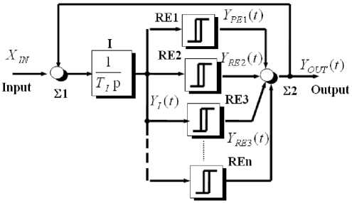
Fig. 1. Block diagram of multi-zone frequency-pulse-width scanning converter with zero conjugation of modulation zones
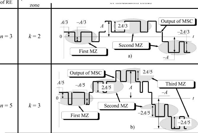
If MSC is turned on and the input signal ХIN is equal to zero, then relay elements are established in an arbitrary way, for example in the state + А /3 (fig. 2c–e). The sequential switching of RE1, RE2 is happening in position – A /3 (fig. 2 c, d; time moments t 01, t 02 ), under the influence of the scanning signal YI ( t ) from the output of the integer (fig. 2b). After that the direction of the scanning conversion changes, and the signal increases YI ( t ) to the positive direction.
If the condition Yt ( t ) = b 1 is true, then MSC is included in stable self-oscillation mode. In this case the amplitude of the scanning signal is limited to ambiguity zone of RE1, and the output signals of RE2, RE3 are located in static and opposite in sign Y RE 2 ( t ), YRE 3 ( t ) (fig. 2 d, e). The output signal of MSC is formed by switching of RE1 (fig. 2 c) in the first modulation zone, which is limited within range ± А /3 (fig. 2f).
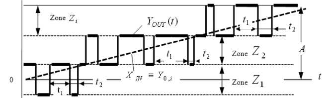
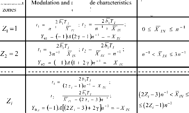
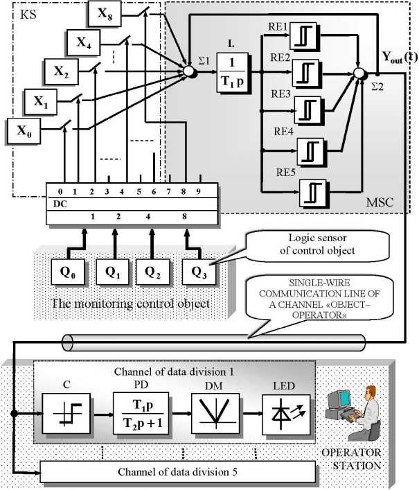
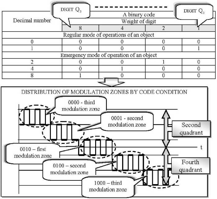
With no signal XN (fig. 2 a; t We assume that at time 10 the signal XN is increased discretely to a value (А/3) < X1N< А (fig. 2 а). This violates the stability of self-oscillation mode in the first modulation zone, and the MSC initiates the reorientation of states of RE2 and RE3. The reorientation ends at time t03 , when RE3 is switched to position –А/3 (fig. 2 e). Output signal reaches the level –А (fig. 2 f) and the MSC switches in the second modulation zone. Where in the intervals t1 , t2 (fig. 2 c) formation rate of scanning function YI (t) (fig. 2b) is determined by the difference or the sum of signals are coming to an adder 21. In this case the signal Y0 includes DC component –А/3 of the first modulation zone and the mean value of the pulse stream YOUT (t) of the second modulation zone (fig. 2 f). The transition of MSC from one modulation zone to another for small increments of coordinates ХIN is accompanied by transition of the system through characteristic points with zero frequency of selfoscillation. It is called the mode of zero frequency conjugation of modulation zones. Modulation and amplitude characteristics of MSC for odd number case of RE are presented in the fig. 3. Fig. 2. Time diagrams of signals of multi-zone integrating frequency-pulse-width scanning converter with zero conjugation of modulation zones Allowable changes range of the input signal ofMSC Modulation ofMSC bx = ^ / ^-normalized value of the switching threshold bx; XIN = v¥/ v / ^ normalized value of the MSC input signal; n - number of relay elements, n>3 - odd number; Zz = 1,2,3... serial number of the modulation zone; у = ^ l^tx -vt^- duty cycle of the MSC output pulses; ± A- the maximum amplitude of the MSC output signal; TT - the time constant of the integrator Fig. 3. Modulation and amplitude characteristics of multizone integrating frequency-pulse-width scanning converter with zero conjugation of modulation zones They show that: • MSC in each modulation zone is a system with frequency-pulse-width modulation. With increasing the signal ХIN the frequency of the output pulses decreases and becomes equal to zero at the boundary between of the modulation zone; • throughout the range of variation of the input signal ХIN the amplitude characteristic of MSC is linear, due to the insular character of the MSC structure and the presence of an integrator in the direct channel of regulation. The analysis shows that the relationship of the number of relay elements of MSC with the number of the modulation zones is determined by the ratio (1) on the fig. 4. So if the minimum allowable value is equal n = 3 , then a number of the modulation zones is 2.0 (fig. 4 а). If n = 3 , then a number of the modulation zones is 3.0 (fig. 4b). And for bipolar modulation the first modulation zone “captures” the second and fourth quadrants of the amplitude characteristic of MSC. The transmission method of the logic data along the single-wire communication line using MSC is considered through the example of thyristor control station for smooth start asynchronous electric drives (fig. 5) [6, 7]. The block diagram of single-wire transmission system of the logic data on control object condition includes the multizone integrating scanning converter (MSC) [6–9], key switchboard KS, decoder DC of an object condition including logic gauges Qi , and also data reception and division channels on the board of the operator. The principle of single-wire logic messages transfer is based on the following. The digital, for example, binary code is given to each of logic sensor of control object (fig. 5). Then the regular and emergency condition of the object is characterized by final number of the code conditions, e.g. five, as it is shown in the code table in a fig. 6. Thus every logic variable transmitted on the board of the operator is allocated with its own modulation zone in the second or fourth Number Number of modulation Diagram of output signal of MSC with zero conjugation of modulation zones If signal of each from relay elements change in the limits ± A / n, than a number of modulation zone of MSC is equal & = (и + 1)/2|и>35 7 - for odd number n (1) MZ - modulation zone; RE - relay element Fig. 4. To analysis of the correlation between the number of relay elements in the basic structure of the multizone integrating scanning converter and the modulation zone number Fig. 5. The block diagram of single-wire logic data transfer system on the board of the operator Fig. 6. Algorithm of the modulation zones distribution on a code condition of the inspected control object quadrant of the “input–output” МSC characteristic (fig. 6). The decoder DC forms on one of the target buses a signal “1”, which is typical only for certain regular or emergency situation of control object. The key switchboard KS contains normally opened keys and sources of basic signals Хi , the number of which is defined by quantity of used target buses DC. Amplitude and mark Хi are chosen so that at switching on of the appropriate key element the target coordinate Yout (t) would appear in required modulation zone of the second or fourth quadrants of the “input–output” МSC characteristic, and with relative duration of pulses equals 0,5 (fig. 6). As a result each situation arising on objects and formed on DC inputs as combinations of “0” and “1”, is transferred to the board of the operator as a logic signal “1”, representing a flow of pulses of the appropriate MSC modulation zone (fig. 6). Each channel of data division (fig. 5) contains the comparator C with switching thresholds adjusted to the “middle” of the appropriate modulation zone, proportionally-differentiating part PD, demodulator DМ and target element of indication, for example, LED. The pulses frequency of each MSC modulation zone corresponds to a proportional section of the PD frequency characteristic. As a result the signal “1” will be formed on a DМ output only of that channel of data division where the comparator C is in a mode of switching with pulses frequency appropriate MSC modulation zone. As the practice has shown, it is expedient to choose the frequency of MSC carrying fluctuations within the limits of 10–20 кHz. Thus the modern element base allows creation of МSC to transfer up to the 30–40 logic data on control object condition along a single-wire communication line. However, it is necessary to take into account that with growth of number of MSC modulation zones the permissible level of the outside handicaps is reduced, as a result of amplitude modulation of the basic information carrier by a handicap signal that the comparators of adjacent data division channels can periodically turn from dynamic into static condition and vice versa [10–14].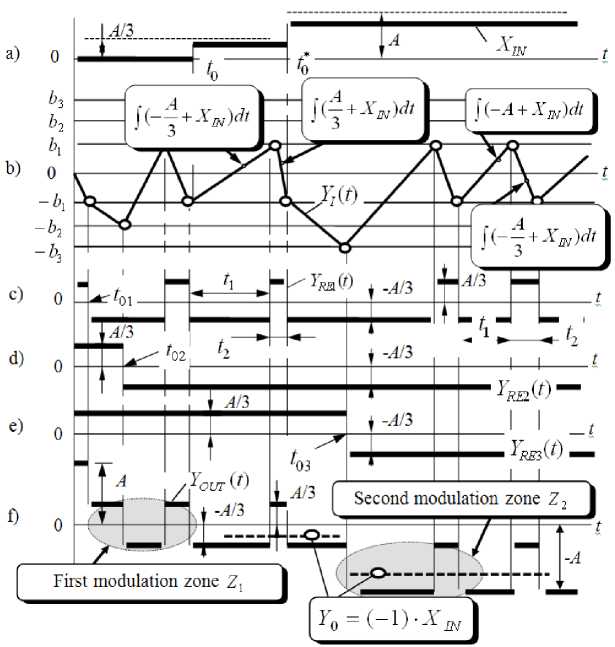
References The way of logical data transmission along a single-wire communication line on the basis of multizone frequency-width-pulse modulation
- Power line communication/H. Ferreira, H. Grove, O. Hooijen, A.J.H. Vinck//Encyclopedia of Electrical and Electronics Engineering (ed. J. Webster), Wiley, 1999. -P. 706-716. DOI: DOI: 10.1002/047134608X.W2004
- Staszewski, R.B. All-digital RF frequency modulation/R.B. Staszewski//Circuits and Systems (ISCAS), 2011 IEEE International Symposium on Digital Object. -P. 426-429. DOI: DOI: 10.1109/ISCAS.2011.5937593
- Kamel, T.S. Advanced distance protection scheme for long Transmission lines in Electric Power systems using multiple classified ANFIS networks/T.S. Kamel, M.A. Moustafa Hassan, A. El-Morshedy//Soft Computing, Computing with Words and Perceptions in System Analysis, Decision and Control, 2009. ICSCCW 2009. Fifth International Conference on. -P. 1-5. DOI: DOI: 10.1109/ICSCCW.2009.5379442
- Becker, T. Digital image data transmission over long distances using image compression and broadband ISDN/T. Becker, R. Simon//Computers in Cardiology. -2001. -P. 687-689. DOI: DOI: 10.1109/CIC.2001.977749
- Wang-Dong Yang A message transmission model based-on channel/Wang-Dong Yang, Qing Zhu//System Science and Engineering (ICSSE), 2012. International Conference on Digital Object. -2012. -P. 509-513. DOI: DOI: 10.1109/ICSSE.2012.6257237
- Пат. 1183988 Российская Федерация. Развертывающий усилитель/Л.И. Цытович. -№ 3734334; заявл. 27.04.1984, опубл. 07.10.1985.
- Analysis of static noise stability of the communication links with width-and frequency-width-pulse carrier of information/L.I. Tsytovich, O.G. Brylina, M.M. Dudkin et al.//Science and Education: materials of the IV international research and practice conference. -2013. -Vol. I. -P. 144-150.
- Дудкин, М.М. Спектральные характеристики развертывающих преобразователей с широтно-импульсной и частотно-широтно-импульсной модуляцией/М.М. Дудкин, Л.И. Цытович, О.Г. Брылина//Электротехника. -2013. -№ 10. -С. 18-25. DOI: DOI: 10.3103/S1068371213100039
- Brylina, O. Electric drive of centrifugal mechanisms with parallel channels of regulation on the basis of multizone sweep converter/O. Brylina, L. Tsytovich//Materiały IX Międzynarodowej naukowi-praktycznej konferencji “Strategiczne pytania światowej nauki -2013”. -2013. -Vol. 30. -P. 55-58.
- Survey of automatic modulation classification techniques: classical approaches and new trends/O.A. Dobre, A. Abdi, Y. Bar-Ness, W. Su//Communications, IET. -2007. -Vol. 1, issue. 2. -P. 137-156. DOI: DOI: 10.1049/iet-com:20050176
- Adian, M.G. Optimal and sub-optimal resource allocation in multiple-input multiple-output-orthogonal frequency division multiplexing-based multi-relay cooperative cognitive radio networks/M.G. Adian, H. Aghaeinia//Communications, IET. -2014. -Vol. 8, issue. 5. -P. 646-657. DOI: DOI: 10.1049/iet-com.2013.0676
- Hemesi, H. Statistical modelling of a non-linear high-power amplifier with memory in multi-input-multi-output orthogonal frequency division multiplexing systems/H. Hemesi, A. Abdipour, A. Mohammadi//Communications, IET, 2014. -Vol. 8, issue. 5.-P. 714-721. DOI: DOI: 10.1049/iet-com.2013.0827
- Адаптивная интервало-кодовая двоично-десятичная интегрирующая синхронизация систем управления силовыми вентильными преобразователями/Л.И. Цытович, О.Г. Брылина, М.М. Дудкин, Р.М. Рахматулин//Электротехника. -2013. -№ 3. -С. 8-15. DOI: DOI: 10.3103/S1068371213030115
- Аналого-цифровой преобразователь с интегрирующей синфазной амплитудно-частотно-импульсной модуляцией для систем вентильного электропривода/Л.И. Цытович, О.Г. Брылина, М.М. Дудкин и др.//Электротехника. -2013. -№ 5. -С. 10-15. DOI: DOI: 10.3103/S106837121305009X
