Three phase induction motor drive using hybrid fuzzy pi controller based on field oriented control

Author: Boonruang Wangsilabatra, Satean Tunyasrirut, Wachirapond Permpoonsinsup
Journal: International Journal of Image, Graphics and Signal Processing @ijigsp
Article in issue: 1 vol.10, 2018.
Free access
The objective of this paper is to present the three phase induction motor drive using the cooperation of fuzzy logic controller and proportional plus integral (PI) controller as a hybrid run on field oriented control (FOC) for improving the performance of rotor speed. The system is fed to a three phase induction motor by voltage source inverter that is used space vector modulation (SVM) technique. This system is implemented with the control system on dSPACE programming which is supported by MATLAB/Simulink through a dSPACE -ds1140 interfacing module. In the implementation, the conventional PI controllers are replaced by hybrid fuzzy PI controllers of both an outer speed control loop and two inner currents control loops that are controlled stator flux and rotor torque of the induction motor. The experimental results are compared with conventional PI controllers. As a result, the performance of design model by hybrid fuzzy PI controller is better than the conventional PI controllers.
Three phase induction motor, Hybrid fuzzy PI controller, Field oriented control
Short address: https://sciup.org/15015927
IDR: 15015927 | DOI: 10.5815/ijigsp.2018.01.01
Text of the scientific article Three phase induction motor drive using hybrid fuzzy pi controller based on field oriented control
Published Online January 2018 in MECS DOI: 10.5815/ijigsp.2018.01.01
Induction motors are widely used in various electrical devices. There are two types of induction motors, single phase induction motors and three-phase induction motors.
The single phase motors are usually applied to single phase electrical system for electrical home devices such as centrifugal pump, electric fan, air-compressor and so on while the three-phase induction motors are usually applied to a three-phase electrical system for industrial applications like the prime-mover in line production system due to their relatively low cost, free maintenance and high reliability [1][2]. The induction motor can be used for a constant speed when the frequency of the voltage source is a constant which is a variable speed in application machine with the advancement of power electronics by generating a three phase supply of variable frequency and voltage with pulse width modulation (PWM) techniques applied to solid state inverter [3]. A simple method to control variable speed of induction motor is constant voltage/frequency ratio (V/f) method to maintain a constant flux in the induction motor drive however this approach has the performance of torque and flux dynamics performance which is extremely poor [4].
The concept of field orientation control (FOC) is proposed by Hasse in 1969 and Blaschke in 1972 that showed the decouple control of flux and torque and it was theoretically possible in three-phase induction motor, As mentioned above it is a same concept of controlling separated exited DC motor [5]. An induction motor has a multi-variable nonlinear coupled structure, some parameter variation due to system disturbances and affect model uncertainty. It leads to difficulty in developing an accurate system mathematical model [6]. The acceleration is difficult to control but it is made linear by operating the method of field orientation control [7].
-
II. Mathemaatical Model of Three-Phase Induction Motor
The dynamic equivalent circuit of the three-phase induction motor is represented in rotating reference frame based on d-q . Let d be the direct axis and q be the quadrature axis. The mathematical model of three-phase induction motor is shown as Fig. 1.
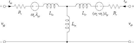
d -axis equivalent circuit
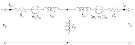
q -axis equivalent circuit
Fig. 1. d-q equivalent circuit of the induction motor [2].
The differential equations of three-phase induction motor can be defined as vs = LL + ^ - ®As dt d^qs vqs = Rsiqs + - ®eLs vdr = 0 = Rridr + ^ — (toe — ®r L dt rL vqr = 0 = Rriqr + q1 + (to - tor L(4)
dt where v is the d-axis stator voltage, v is the q-axis stator voltage, v is the d-axis rotor voltage, v is the q-axis rotor voltage, i is the d-axis stator current, i is the q-axis stator current, i is the d-axis rotor current, i is the q-axis rotor current, R is the stator resistance, R is the rotor resistance, ®e is the angular velocity of the reference frame, ®r is the angular velocity of the rotor frame, and L , L, L, L are flux linkages. If Equation (3) and Equation (4) are equal to zero, then the flux linkages can be written as
L = Lsids + Li(5)
L = Liqs + Lmiqr
^dr = LL + Lmirs(7)
ids
L r
LL - 1} rs m
^sL^-r Lr rs LL -L rr rs m
|
i qs |
L r LL - |
L 2 m |
L qs |
L m LL - |
L 2 m |
L qr |
(10) |
|
idr |
L s LL - |
L 2 m |
L |
L m LL - |
L 2 m |
■ Lrs |
(11) |
|
i qr |
L s LL - |
L 2 m |
L |
L m LL - |
L 2 m |
■ ^qs |
(12) |
The electromagnetic torque and rotor speed of the machine are as follows
3 P
T =—L (i i, -iqi ) e m qs dr ds qr rtoL = P_ (t — t )
dt 2 J eL
where T is the electromagnetic torque, P is the number of poles, J is the inertia of rotor and T is the load torque.
-
III. Vector control of Induction machines
Vector control or flux oriented control is the most popular control technique of AC induction machines. The components of the stator current in the motor are represented by a vector, in a special rotating reference frame [1], the expression of the electromagnetic torque of the smooth-air-gap machine is similar to the expression of torque in a separately exit exciting DC machine. Field oriented control is the principle of vector control of electrical drives. It is based on the control of both the magnitude and the phase of each phase current and voltage [1]. In the case of induction motor, the control is usually performed in the reference frame d - q attached to the rotor flux space vector. There are two strategies of FOC. First is direct field oriented control (DFOC) and second is indirect field oriented control (IFOC) which is widely used for implementation of the FOC system because the rotor flux vector can be estimated by using only current model of the field oriented control equations. where a - axis , в -axis are stationary reference frames, ia , i p are the current components of stationary reference
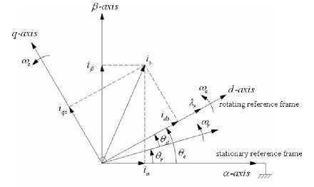
Fig. 2. Phasor diagram of the FOC scheme
frame and d - axis , q - axis are rotating reference frames, i , i are the current components of rotating reference frame, ^ is synchronous speed, Xr is rotor flux, o r is rotor speed, 9 is the angular of rotor speed, 9 is the angular of synchronous speed and p is the angular of
According to Fig. 3, there is transformation between stationary frame and rotating frame by using Clark transformation, inverse Clark transformation, Park and inverse transformation.
From stationary a-b-c frame, Clark transformation can be converted as slip speed.
Fig. 2, shows the phasor diagram which is described the FOC scheme. The stationary reference frame is fixed to a - axis . The stator current of the three-phase induction motor can be transformed into i and i and they can be
J
- 1
- 1
"3
- 1
73 _
ia
ib ic
converted into i and i .
Fig. 3, shows the basic concept of field orientation control of three-phase induction motor.
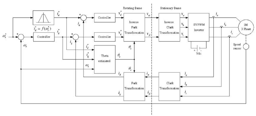
Fig. 3. Field orientation control of three-phase induction motor.
In stationary a-p frame to rotating d-q frame, Park transformation can be expressed as id cos 9 sin 9e
_ iq J [-sin 9e cos 9e a ip
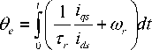
Again in Fig. 3, the control system is separated into two control loops, inner two current loops and outer speed control loop, respectively. The rotor flux and torque quantities are evaluated by the relation of angular velocities and synchronous angular. The synchronous angular can be estimated as
In rotating d-q frame to stationary a - P frame, inverse
Park transformation is as
|
i a |
cos 9, |
- sin 9e " |
i d |
|
|
i P _ |
_ sin 9 e |
cos 9 |
_ i q |
Inverse Clark transformation from stationary frame to stationary a-b-c frame can be defined as
_ i P _
a - p
where 9 is synchronous angular, тг is rotor time constant, i is stator q -axis current and i is stator d -axis current.
By considering Fig. 3, the controllers can be replaced by PI controller, fuzzy logic controller, fuzzy logic controller including PI controller or another controller scheme to operate the control system.
In addition to the conventional controllers of Fig. 1, PI controllers have high overshoot, oscillation of speed and torque because of sudden changing of command speed and external load disturbances [8].
-
IV. PI Controller
In a control system, PI controller can reduce the maximum overshoot and the time response to load disturbance effect. The practical form of controller composes of proportional (P) and integral (I) as shown in equation (20) and (21), respectively.
P = KPe (t)(20)
I = K je (t)dt(21)
The PI controllers in the time domain can be expressed by u (t) = Ke (t) + K je (t) dt(22)
By Laplace Transform, equation (22) can be written as
UM = k, + K
E(s)
IF-THEN general structure which uses the human experience and logic [11][12]. The FLC has been widely applied not only for nonlinear system but also for control induction motor system [13]. However, the FLC has some disadvantages also as it may use more computations [14].
|
Input —► |
Fuzzification |
Inference Engine |
Defuzzification |
—► Output |
||
|
f Knowledge |
||||||
Fig. 5. Block diagram of fuzzy logic controller
The block diagram of fuzzy logic controller is depicted in Fig. 5, which consists of four modules. Firstly, the fuzzification module performs into membership function of input variable such as Negative Large (NL), Negative Small (NS), Zero (ZE), Positive Small (PS) and Positive Large (PL). Secondly, defuzzification converts a degree of membership of output linguistic variables into numerical values. Thirdly, it uses the center of gravity or centroid of area (COA) method. Finally, the knowledge bases are included inference engine which is defined into the rules represented as IF-THEN rules statements.
Equation (23) is a transfer function (output/input) and shows in the block diagram as Fig. 4.
VI. Hybrid Fuzzy Logic pi Controller
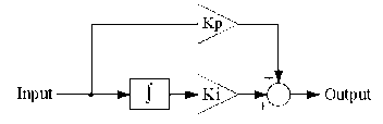
Fig. 4. Block diagram of PI controller
Where the input is an error signal between reference command and feedback signal and the output is a control signal. The output signal from PI controller is updated by gain K P and K i based on a set of rules to maintain the best control performance even in the presence of parameter variation and nonlinearity of the process. If the gains of the controller exceed a certain value, then the variations in the output signal become to high and will destabilize the system. This problem can be solved by using limiter ahead of the PI controller. This limiter causes the error signal to be maintained within the saturation limits of the output control signal [9].
Fig. 6, shows the block diagram of hybrid fuzzy logic PI controller that composing fuzzy logic controller, integrator with gain ( K i ) and proportional gain ( K P ) that are summed to generate output control signal.
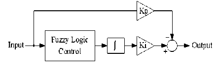
Fig. 6. Block diagram of hybrid fuzzy PI Controller
The transfer function (TF=output/input) of the block diagram in Fig. 6. It can be written as
к
TF = KP + -^ ( COA )
-
V. Fuzzy Logic Controller
Fuzzy Logic Controller (FLC) is one of an intelligent control method. The FLC has various advantages. It does not need of the exact system mathematical model. It is able to handle the nonlinearity, complexity of the system. Furthermore, it is robust and its efficiencies are not sensitive to the parameter variations. Hence, it is compared to the conventional PI controller [10]. The conception of FLC is based on the linguistic rule with an
-
VII. Space Vector Pwm Inverter
Space vector pulse width modulation (SVPWM) is applied to drive the induction motor with voltage source inverter (VSI) because it has less harmonics and larger than the modulation range that extends the modulation factor to 90.7% from the traditional value of 78.5% in sinusoidal pulse width modulation (SPWM) [15][16].
SVPWM refers to the switching sequence of power electronic switches device (Power Transistor BJTs,
Power MOSFETs or IGBTs) of the upper three device of three-leg voltage source inverter as shown in Fig. 7.
Fig. 9, expresses the projection of the reference voltage vector for V 6 .
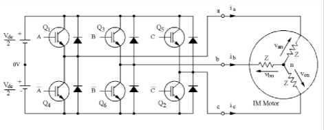
Fig. 7. Three-leg voltage source inverter
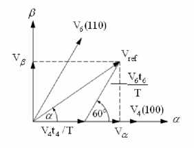
Fig. 9. Projection of the reference voltage vector for V 6
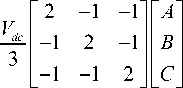
According to Fig. 7, an upper power electronic switch is switched on (Q 1 , Q 3 , Q 5 are 1) the corresponding lower power electronic switch as the same leg is switched off (Q 4 , Q 6 , Q 2 are 0). Therefore, the on and off states of power electronic switches that are referred to the switching variable (A, B, C). It can be determined each phase to neutral voltage for every switching combination of the switching variable as
Notice that the magnitude and reference angle in Fig. 9, can be determined as equation (27) and equation (28), respectively as
V an
V bn
V cn
| V ref\ = V V + V 2 (27)
a = tan - 1 ( V e I V a ) (28)
In vector control algorithm, the control variables are represented in the rotating frame. The current vector is transformed into voltage vector by the inverse Park transformation. This voltage reference is expressed in the stationary а - в frame. The three phase voltages in а - в frame are given by using Clarke transformation. It can be demonstrated as
V a
V j
- i
- i 3 - i
Vs Vs J L
Van
Vbn
Vcn
VIII. Experimental Setup
Fig. 10, shows the experimental setup that consists of PC which is installed on MATLAB/Simulink version 7.1 programming software and dSPACE version ds-1104 programming software for controlling the operation of this system. PWM inverter can drive the three phase induction motor with coupling to an incremental encoder for sensing the speed of the induction motor and coupling to the dynamics load for inserting the disturbance torque to the motor. The current sensors that are used for measurement the current is fed to the motor. The input and output of control signal that are sent to the PC by using dSPACE-ds1104 interfacing module [17].
Fig. 8, illustrate the basic voltage space vectors, these are projected in а - в frame. There are six nonzero vectors (V1 to V6) and two zero vectors (V0 and V7).
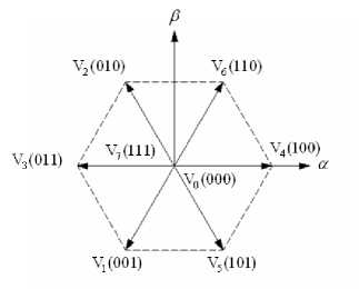
Fig. 8. Basic voltage space vectors
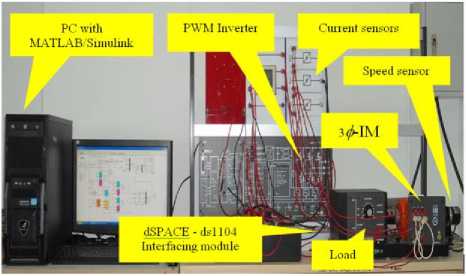
Fig. 10. Experimental setup
Table 1. shows the specification of a three-phase induction motor. Where R is the stator resistance, R is the rotor resistance, L is the magnetizing inductance, L is the stator leakage inductance, L is the rotor leakage inductance and J is the inertia of rotor.
Table 1. Specification of a three phase induction motor
|
Parameter |
Specification |
Parameter |
Specification |
|
Rated voltage |
220V/380V |
Rs |
82.4 Ω |
|
Rated current |
0.78A/0.45A |
R r |
98.11 Ω |
|
Rated power |
0.12kW |
Lm |
3.42H |
|
Frequency |
50Hz |
Lls |
0.21H |
|
Rated speed |
2600 rpm |
Llr |
0.26H |
|
Poles |
2 |
J |
0.00016kg-m 2 |
As referred to earlier, the conventional PI controllers would be replaced by hybrid fuzzy PI controllers of both an outer speed control loop and two inner current control loops running on field oriented control for improving the performance of rotor speed and stator current of the three-phase induction motor.
Fig. 11, depicts MATLAB/Simulink diagram for implementation of three-phase induction motor drive. The switch 1 to switch 3 are used for selecting the controller scheme between the conventional PI controllers and the hybrid fuzzy PI controllers while the pulse generator is used for generating input of speed command signal reference. The parameters for the field oriented control system can be defined in Table 2. that illustrates the gain parameters of PI controllers and hybrid fuzzy PI controller.
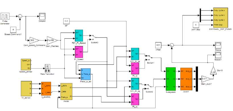
Fig.11. MATLAB/Simulink model for implementation of three-phase induction motor drive.
Table 2. The gain parameter of PI controllers and hybrid fuzzy PI controllers
|
Controller schemes |
Parameter |
Gain |
Parameter |
Gain |
Parameter |
Gain |
|
PI |
kp_ω |
0.01 |
k p_iq |
230 |
k p_id |
230 |
|
ki_ω |
0.05 |
ki_iq |
7500 |
ki_id |
7500 |
|
|
Hybrid |
kp_ω |
0.01 |
k p_iq |
230 |
k p_id |
230 |
|
fuzzy PI |
ki_ω |
0.05 |
ki_iq |
7500 |
ki_id |
7500 |
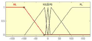
Fig. 12(a) and (b) show the both input and output membership functions of Fuzzy PI_ ω .
(a) Input
HL NSZE PS PL
•15 -10 -5 0 5 10 15
(b) Output
Fig. 12. Membership function of Fuzzy PI_ ω
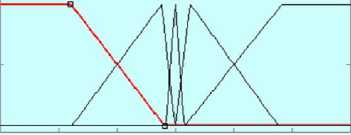
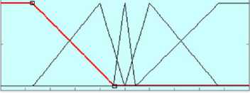
The input and output membership functions of Fuzzy PI_id and Fuzzy PI_iq are expressed in Fig. 13(a) and (b), respectively.

-10-8-6-4-2 0 2 4 6 8 10
(a) Input
HL NS ZE PS PL
■10 -8 -в -4 -2 0 2 4 в в 1»
(b) Output
Fig. 13. Membership function of Fuzzy PI_id and Fuzzy PI_iq
In Fig. 12 and Fig. 13, the membership functions have fuzzy variables that are Negative Large (NL), Negative Small (NS), Zero (ZE), Positive Small (PS) and Positive Large (PL). The rule for fuzzy inference engines of hybrid fuzzy PI controller is shown in Table 3.
Table 3. Rule for fuzzy inference engines of hybrid fuzzy PI controller
|
Fuzzy PI _ ω |
|||||
|
Error |
NL |
NS |
ZE |
PS |
PL |
|
Rule |
NL |
NL |
ZE |
PL |
PL |
|
Fuzzy PI_ id and Fuzzy PI_ iq |
|||||
|
Error |
NL |
NS |
ZE |
PS |
PL |
|
Rule |
NL |
NL |
ZE |
PL |
PL |
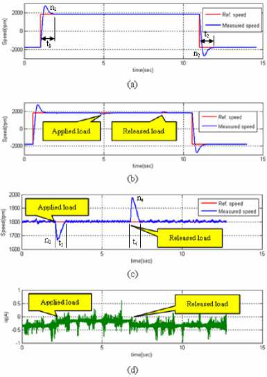
Fig. 14. Step response of speed for case A
-
IX. Experimental Resualts
The experimental results would be classified in four cases that depend on select switch 1 to switch 3 for choosing the controllers to control outer speed control loop and two inner current control loops. All of the results are under same condition such as same gain parameters of both the conventional PI controllers and the hybrid fuzzy PI controller that is shown in Table II. In the same disturbance of load torque, the step response to speed of three phase induction motor is observed.
-
A. Outer speed control loop and two inner current control loops using the conventional PI controller
The experimental results of this case show in Fig. 14.
According to Fig. 14, reference speed is fixed to + 1800 rpm. Fig. 14(a) shows no-load speed of step response. It has high overshoot both clockwise and counters clockwise speed of turning speed.
Fig. 14(b), shows the step response and disturbance of load torque shows in Fig. 14(c). They have both high overshoots whilst applied load and release load and i q is generated during load torque applied as shown in Fig. 14(d).
-
B. Outer speed control loop and two inner current control loops using the hybrid fuzzy-PI controller
For case B, the experimental results shows in Fig. 15.
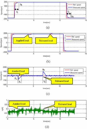
Fig. 15. Step response of speed for case B
In considering Fig. 15(a), it has included no-load speed of step response and also it has no overshoot both clockwise and counters clockwise speed of turning speed.
Fig. 15(b) shows the step response and disturbance of load torque as shows in Fig. 15(c). The waveform of them has also low overshoot when the load disturbance is applied and released. Notice that the overshoot is lower than in case A and i q is generated during load torque applied as shown in Fig. 15(d).
-
C. Outer speed control loop using the conventional PI controller and two inner current control loops using the hybrid fuzzy-PI controller
The experimental results of case C show in Fig. 16.
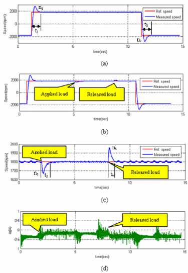
Fig. 16. Step response of speed for case C
The no-load speed of step response is shown as Fig. 16(a). It has high overshoot both clockwise and counter clockwise speed of turning speed like in case A. Again, the overshoot of on-load speed of step response and disturbance of load torque are lower than in case A but higher than in case B that shows in Fig. 16(c). Note that, i q is generated during load torque is applied in Fig. 16(d).
-
D. Outer speed control loop using the hybrid fuzzy-PI controller and two inner current control loops using the conventional PI controller
As will see in Fig. 17, the experimental results are shown as follows. In Fig. 17(a), it shows no-load speed of step response. Obviously, it has no overshoot both clockwise and counters clockwise speed of turning speed.
In particular, Fig. 17(b) depicts the step response and disturbance of load torque that shows in Fig. 17(c). They have both high overshoot also when apply and release load like case A and their overshoots are higher than case B and once more i q is generated during load torque applied as shown in Fig. 17(d).
The overshoot of speed response n 1 to n 4 and the duration of time response t 1 to t 4 are shown in Table 4 and Table 5., respectively.
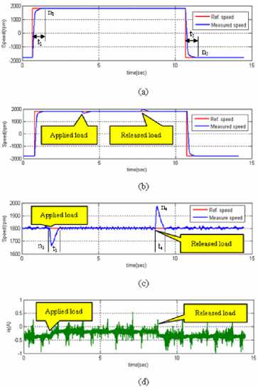
Fig.17 Step response of speed for case D
Table 4. No load speed response
|
Controller schemes |
n 1 rpm |
Over shoot (%) |
n 2 (rpm) |
Over shoot (%) |
t 1 (sec) |
t 2 (sec) |
|
PI-PI |
2750 |
52.78 |
-2750 |
52.78 |
1.16 |
1.06 |
|
HFZY-HFZY |
0 |
0 |
0 |
0 |
0.68 |
0.64 |
|
PI-HFZY |
2750 |
52.78 |
-2750 |
52.78 |
1.16 |
1.06 |
|
HFZY-PI |
0 |
0 |
0 |
0 |
0.754 |
0.743 |
Table 5. Disturbance of load torque response
|
Controller schemes |
n 3 rpm |
Over shoot (%) |
n 4 (rpm) |
Over shoot (%) |
t 3 (sec) |
t 4 (sec) |
|
PI-PI |
1648 |
-8.50 |
1985 |
10.28 |
1.15 |
1.00 |
|
HFZY-HFZY |
1725 |
-4.17 |
1905 |
5.83 |
0.73 |
0.70 |
|
PI-HFZY |
1667 |
-7.40 |
1962 |
9.01 |
0.74 |
0.72 |
|
HFZY-PI |
1663 |
-7.61 |
1970 |
9.44 |
0.93 |
1.28 |
-
X. Experimental discussion
The no load speed response shows in Table 4. The overshoot of speed depends on the outer speed control loop. In outer speed control loop using the conventional PI controller, it has very high overshoot of speed and duration of time response which is very slow. For the outer speed control loop using the hybrid fuzzy-PI controller, it has no overshoot of speed and duration of time response then it is faster than using a conventional PI controller.
Reasonably, the transfer function of hybrid fuzzy-PI controller by using equation (24) compares with the transfer function of conventional PI controller represented by equation (23). The output of the FLC is COA similar to an adaptive dynamics gain and it multiplies with integral gain (Ki) under the same gain parameter show in Table 2. The output of hybrid fuzzy-PI controller is an adaptive dynamics gain also then it leads to the time response which is faster than conventional PI controller and it is possible to give no overshoot of the on load speed response.
The disturbance of load torque response shows in Table 5, the overshoot of speed depends on the two inner current control loops. In inner current control loops using the conventional PI controller, it has high the overshoot of speed and duration of time response and it is slow either. In the inner current control loops using the hybrid fuzzy-PI controller, if it has low overshoot of speed and duration of time response then it is also faster than using a conventional PI controller.
As mention previous, because the two inner current control loops are i and i for control the stator flux and the rotor torque of the induction motor. If the two inner current control loops are the best regulated by the good performance of control system. Again, the output of hybrid fuzzy-PI controller is an adaptive dynamics gain and the time response is faster than conventional PI controller. It leads to the overshoot of speed which is lower than conventional PI controller while the disturbance of load torque is applied to the induction motor.
-
XI. Conclusions
The experiment results show the performance of steady state error of rotor speed bases on the field oriented control using hybrid fuzzy-PI controller both in outer speed control loop and two inner current control loops is convergence to zero. It is effective more than conventional PI controller. Moreover, the overshoot of step response, no load speed response and disturbance of load torque response, including the duration time response, is better than a conventional PI controller. Therefore, the method can maintain the constant speed at any range and good response of both input command and good response of duration time of the disturbance of load torque.
Acknowledgement
This paper is supported by Faculty of Electrical Engineering, Pathumwan Institute of Technology.
The authors wish to thank the reviewers for their constructive comments. Also, they wish to thank the Editors for their generous comments and support during the review process.
References Three phase induction motor drive using hybrid fuzzy pi controller based on field oriented control
- M. Sulaiman, F. A. Patakor and Z. Ibrahim, “DSP Based Implementation of Field Oriented Control of Three-Phase Induction Motor Drive”, IJRET; International Journal of Research in Engineering and Technology, Volume:02 Issue:09, Sep-2013, pp. 179–186.
- Azuwien Aida Bohari,Wahyu Mulyo Utomo,Zainal Alam Haron, Nooradzianie Muhd. Zin, Sy Yi Sim, Roslina Mat Ariff, “Speed Tracking of Indirest Field Oriented Control Induction Motor using Neural Network”, ScienceDirect, Procedia Technology 11, 2013.pp. 141-146
- A. W. Leedy, “Simulink/MATLAB Dynamic Induction Motor Model for Use as Teaching and Research Tool”, International Journal of Soft Computing and Engineering (IJSCE), ISSN: 2231-2307, Volume-3, Issue-4, September, 2013, pp. 102–107.
- B. A. and M. Bhardwaj, “Sensored Field Oriented Control of 3-Phase Induction”, Texas Instruments, Application Report, July, 2013.
- A. M. Trzynadlowski, “Control of Induction Motor”, Academic Press, Harcourt Place, 32 Jamestown Road, London NW1 7BY, UK, 2001.
- Ravi Sharma, Renu Singh, “Analysis of Transient Response and Load Disturbance Rejection Ability of Induction Motor using Fuzzy Logic Approach”, I.J. Intelligent System and Application, 2014,08,10-18, Published Online July 2014 in MECS, pp. 10-18.
- Rizana Fauzi, Dedid Cahya Happyanto, Indra Adji Sulistijoono, “Fast Response Three Phase Induction Motor Using Indirect Field Oriented Control (IFOC) Base On Fuzzy-Backstepping”, EMITTER International Journal of Engineering Technology Vol.3 No.1, June 2015.
- Arun Kumar R, “Indirect Field Oriented Control of Induction Motor Using Fuzzy Logic”, ResearchGare, Conference Paper, November 2012, Retrived on :02 January 2016.
- Salima Lekhchine, Tahar Bahi, Youcef Soufi, “Indirect rotor field oriented control base on fuzzy logic controlled double star induction machine”, Electrical Power and Energy System 57, 2014, pp.206-211
- Gauri V. Deshpande, S.S. Sankeshwari, “Speed Control of Induction Motors Using Hybrid PI Plus Fuzzy Controller”, International Journal of Advances in Engineering & Technology, Nov. 2013.
- Ishaya Emmanuel, “Fuzzy Logic-Base Control for Autonomous Vehicle: A Survey”, I.J. Education and Management Engineering, 2017, 2, 41-49, Published Online March 2017 in MECS.
- Pushpa Mamoria, Deepa Raj, “Comparison of Mamdani Fuzzy Inference System for Multiple Membership Functions”, I.J. Image, Graphics and Signal Processing, 2016, 9, 26-30, Published Online September 2016 in MECS.
- Preeti, Dr. Narendra Singh Beniwal, “Comparison of Conventional and Fuzzy P/PI/PI/PID Controller for Higher Order Non Linear Plant with High Dead Time”, International Journal of Scientific and Research Publication, Volume2, Issue8, August 2012.
- Gurmeet Singh, Gagan Singh, “Modeling and Simulation of Indirect Field Oriented Control of Three phase Induction Motor using Fuzzy Logic Control”, International Journal of Engineering Research & Technology (IJERT), Vol.3 Issue 8, August – 2014.
- Rui Zhang, “Research on Space Vector Pulse Width Modulation Power”, International Journal of Signal Processing, Image Processing and Pattern Recognition, Vol.6, No.6, 2013, pp.93-100.
- A.O.Amalkar, Prof.K.B.Khanchandani, “Design Analysis and Implementation of Space Vector Pulse Width Modulation Inverter Using DSP Controller for Vector Controlled Drives”, International Journal of Electrical Engineering & Technology (IJEET), Volume6, Issue 3, March 2015, pp.32-44.
- https://www.artisantg.com/ViewImage.aspx?Image=dSPACE_CLP1104_View1_201663013420.jpg%20&Item=8, access on March 6 2017.
