Threshold based Image Fusion in Dual Tree Complex Wavelet Domain

Author: Richa Srivastava, Ashish Khare
Journal: International Journal of Image, Graphics and Signal Processing(IJIGSP) @ijigsp
Article in issue: 10 vol.8, 2016.
Free access
Image fusion is a popular application of image processing which performs merging of two or more images into one. The merged image is of improved visual quality and carries more information content. The present work introduces a new image fusion method in complex wavelet domain. The proposed fusion rule is based on a level dependent threshold, where absolute difference of a wavelet coefficient from the threshold value is taken as fusion criteria. This absolute difference represents variation in the image intensity that resembles the salient features of image. Hence, for fusion, the coefficients that are far from threshold value are being selected. The motivation behind using dual tree complex wavelet transform is due to failure of real valued wavelet transform in many aspects. Good directional selectivity, availability of phase information and approximate shift invariant nature of dual tree complex wavelet transform make it suitable for image fusion and help to produce a high quality fused image. To prove the strength of the proposed method, it has been compared with several spatial, pyramidal, wavelet and new generation wavelet based fusion methods. The experimental results show that the proposed method outperforms all the other state-of-the-art methods visually as well as in terms of standard deviation, mutual information, edge strength, fusion factor, sharpness and average gradient.
Image fusion, dual tree complex wavelet transform, level dependent threshold, threshold based fusion, multiresolution analysis
Short address: https://sciup.org/15014033
IDR: 15014033
Text of the scientific article Threshold based Image Fusion in Dual Tree Complex Wavelet Domain
Published Online October 2016 in MECS
Image fusion [1-4] is a process to extract the complementary or redundant features from the multiple source images of the same scene and then, fuse them into a single composite image with more dependent and more comprehensive information. The fused outcome is more useful for human and machine perception and for further image processing tasks. Replacement of multiple images by a single one also reduces the processing time and storage space. These benefits increase the popularity of image fusion in different application areas like medical imaging, remote sensing, satellite imaging, biometrics etc.
Medical imaging deals with several types of multimodal images like computed tomography (CT), magnetic resonance imaging (MRI), positron emission tomography (PET), single photon emission computed tomography (SPECT), functional magnetic resonance imaging (fMRI) etc. These multimodal images contain complementary functional or anatomical information of different organs. For example, PET image contains functional information of organs whereas the MRI provides anatomical information of the body. Likewise, remote sensing imagery involves multispectral and panchromatic images. Multispectral images are of high spectral resolution whereas the panchromatic images are of high spatial resolution. Similar problems occur in case of many other fields of imaging. Thus, there is a need to process several modalities of images because the required information is scattered in different images. Use of image fusion technique will process the complementary images to produce a single image having all important features of the respective source images. A detail discussion on different image fusion techniques is given in section 2.
In this work, we have proposed a novel level dependent threshold based fusion method using dual tree complex wavelet transform. This level dependent threshold is based on standard deviation of complex wavelet coefficients, mean, median of absolute complex wavelet coefficients. We have incorporated this threshold as a fusion rule by taking absolute difference of each coefficient from the threshold. This threshold works because absolute difference of wavelet coefficients from the threshold resembles the variation in the intensity values and so to the salient features of the image like edges or curves. To demonstrate the efficiency of the proposed method, we have performed experiments in which the proposed method is compared with several existing spatial and transform domain fusion methods. Results of our experiments show that the proposed method is superior to all the other state-of-the-arts methods visually as well as in term of statistical quantitative measurements like, standard deviation, mutual information, edge strength, fusion factor, sharpness and average gradient.
The rest of the paper is organized as follows: Section 2 gives literature review on existing image fusion methods.
Section 3 introduces the fundamental structure and properties of dual tree complex wavelet transform. Section 4 describes the proposed fusion method. Details of fusion metrics used for comparison of different methods are given in Section 5. Experimental results and their analysis are given in section 6. Finally, whole work is concluded in Section 7.2
-
II. Related Works
Image fusion methods are classified into three broad categories- pixel level fusion, feature level fusion and decision level fusion. Pixel level fusion is the simplest and efficient method among the three categories because here, fusion is applied directly on the pixels of image. Pixel level fusion is further divided into spatial domain [5-6] and frequency domain [7-9] methods. Spatial domain methods perform fusion directly on image pixels. Weighted averaging is a simple spatial domain fusion method but it suffers from reduced contrast problem. Principal component analysis (PCA) [5], Brovey transform and intensity-hue-saturation (IHS) [6] based methods are some other spatial domain fusion methods with improved performance. They generate high spatial quality image but often suffer with spectral distortions. Another category of pixel level fusion is frequency domain methods which avoids the shortcomings of spatial domain methods. In frequency domain methods, multiresolution analysis (MRA) commences a new era in image fusion. MRA is based on human visual perception that views an image as several components of different resolutions. In MRA based fusion, source images are converted into several components of different resolutions and then, these components are combined using an appropriate fusion rule. The fused image is then obtained from the combined component set by applying inverse transform. Pyramid transform and wavelet transform are the most popular methods based on multiresolution principle. In pyramid transform, images are divided into multiple pyramids of varying resolution. Laplacian pyramid (LP), gradient pyramid [10], contrast pyramid, ratio of low pass pyramid, morphological pyramid are few examples of pyramid transforms. The main problem with pyramid based methods is lack of spatial orientation selectivity, which results in blocking effect in the fused image [11]. Use of wavelet transform can avoid this shortcoming. Wavelet transform gives a compact, less redundant and more directional solution in form of discrete wavelet transform (DWT). Many researchers have worked on DWT for different applications [7, 12] and observed that this real valued discrete wavelet transform (DWT) has limited directionality, lack of phase information and is shiftvariant in nature. To solve the above problems, scholars have been motivated to explore the complex valued world in place of real valued world. Kingsbury [13] had proposed the concept of dual tree complex wavelet transform (DTCWT) that exploits two DWT, one for real part and other for imaginary part of the transform. DTCWT provides more directional selectivity, phase information, shift-invariance and less redundancy as compared to DWT. These properties provide sufficient strength to DTCWT to produce good fusion results.
So far several fusion rules have been developed by researchers in literature. Burt [10] has proposed a multiresolution fusion framework with ‘absolute maximum selection’ fusion rule. Because of its simplicity this fusion rule has become very popular and used by many researchers [3, 14, 15] in different areas of image processing. But, this fusion rule is based only on the selected current wavelet coefficient and knows nothing about the dependency or relationship among the coefficients. Therefore, sometime it fails to incorporate salient features of images. Burt and Kolczynski [16] have proposed another fusion rule based on activity measure and matches a measure value which is based on window based selection. In window based fusion rule, selection is based on a group of coefficients rather than a single coefficient. Similar fusion rules have been defined in [11, 17] in the form of energy based, window based and activity measure based fusion rule. Besides these standard fusion rules, some more complex fusion rules have also been proposed. Yang et al. [18] have proposed a fusion rule based on Log-Gabor energy. It is based on Log-Gabor filter. Another contrast sensitivity based fusion is proposed in [19] by Wilson et al. This fusion is based on weighted energy in human perceptual domain that depends on the frequency domain. In most of the fusion rules the low frequency coefficient didn’t get attention and obtained by just averaging operation. It may decrease the contrast of fused image [20]. In the present paper, we have proposed a new fusion rule that avoids the problems of earlier proposed rules. The proposed fusion rule is based on the statistical properties of DTCWT coefficients of image. The proposed fusion rule neither depends on a single coefficient nor does it perform averaging operation on low frequency coefficient. Unlike the other complex fusion rules, its implementation is as simple as ‘absolute maximum selection’ or window based fusion rule. The proposed fusion rule depends on a threshold proposed by [21] and some statistical properties. The detail about the proposed fusion rule is discussed in section 4.
-
III. Multiresolution Analysis with Dual Tree Complex Wavelet Transform
Multiresolution analysis (MRA) [22] is an advanced tool, which has been successfully used by many researchers for signal analysis and image processing tasks. In MRA, an image is decomposed into different decomposition levels which contain coefficient sets of variable frequencies. These coefficient sets are processed for a particular task and then, inverse transform is applied to get the final processed image. Wavelet transform is the most popular tool of MRA. Wavelet transform can be categorized into real valued and complex valued wavelet transforms. Real valued wavelet transform uses realvalued filters to get real valued coefficients while complex wavelet transform uses complex valued filters to get complex valued coefficients. No doubt that the real valued wavelet transform (DWT) has better sparse representation and efficient computation but, it suffers from the following problems:
Shift variance: In real valued wavelet transform, small change in the input signal may cause a substantive change in the energy distribution of decomposition levels.
Lack of directionality: DWT is limited to only three directions (horizontal, vertical and diagonal), due to which it is not efficient in capturing curves and edges in other directions.
Oscillations: Because a bandpass function is used in computation of real-valued wavelet transform, wavelet coefficients oscillate in positive and negative directions around singularity. It makes the singularity extraction and signal modeling difficult in real-valued wavelet transform.
Aliasing: The iterated downsampling in the computation of real-valued wavelet transform results in aliasing which causes artifacts in the reconstructed signal.
To obtain the solution of the above problems, researchers revisited the Fourier transform and found that Fourier transform does not suffer from some of the problems of DWT because it uses complex valued sinusoid functions. This fact motivated researchers to switch over complex domain to make a complex wavelet transform. Kingsbury [13] proposed a complex wavelet transform and named it as Dual-tree complex wavelet transform (DTCWT). DTCWT uses two real DWT in parallel. One DWT generates real part and the other generates imaginary part of DTCWT [13].
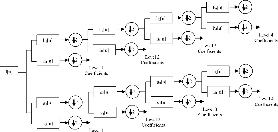
Coefficients
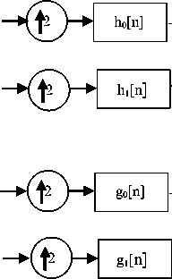
Fig.1. Analysis Filter Bank for dual tree complex wavelet transform.
Fig.2. Synthesis Filter Bank for dual tree complex wavelet transform.
The analysis and synthesis filter banks of DTCWT are shown in Fig. 1 and Fig. 2 respectively. In both parts of DTCWT, two different filters are used and each of them satisfies the condition for perfect reconstruction. The filter pair is constructed in a manner that the transform is approximately analytic. Let h 0 (n) , h 1 (n) are the low pass and high pass filters for the first wavelet (^ h (t)) tree and g0(n) , g1(n) are the low pass and high pass filters for the second wavelet (y g (t)) tree. The two wavelets together construct the dual-tree complex wavelet ^(t) as shown in equation (1):
V ( t ) = ' ( t ) + i / g ( t ) (1)
To make the transform analytic and shift independent, the two wavelets are chosen so that they form approximately Hilbert pair or in other words one filter is half-sample shift of the other [23], i.e.
' ( t ) « H ' h ( t ) } (2)
Though DTCWT is a complex wavelet transform, but the filters that it uses are all real valued. So, no complex computation is involved in its implementation, making it computationally efficient. In 2-dimension, DTCWT is achieved by applying filters separately along rows and columns. If both filters suppress negative frequencies, then only first quadrant of the spectrum is obtained. However, to completely represent a 2-D signal, two adjacent quadrants of the spectrum are required. Therefore, complex conjugates of the row filters are used. In comparison to the 2-D DWT, 2-D DTCWT gives six sub-images (three sub-images each in two quadrants) resulting in six bandpass images containing complex coefficients. The subbands are strongly oriented in the directions ±15o, ±45o, ±75o. Strong orientation is the result of separation of positive and negative frequencies by filters. Thus, in each decomposition level DTCWT decomposes an image into one scaling subband and six wavelet subbands oriented in six directions ±15o, ±45o, ±75o. Therefore, in DTCWT, we can achieve good directional selectivity, phase information, perfect reconstruction and approximate shift- invariance without involving complex computations.
-
IV. The Proposed Method
Absolute maximum fusion rule is simple in nature. However use of absolute maximum fusion rule has a serious disadvantage that sometime noisy coefficients are selected during the fusion process. To avoid this problem, a threshold based fusion rule has been proposed in this paper. The threshold, the fusion rule and the algorithm are described in consequent sub-sections of this section.
-
A. The Threshold
Wavelet based thresholding is the most popular tool for reducing noise present in the images. In thresholding, we compare the values of wavelet coefficients with the threshold value and preserve them if their absolute values are greater than the predefined threshold. In the present work, we have utilized this concept in image fusion. In denoising, we discard the coefficients having lower absolute values than the threshold, because the noise affects the small value wavelet coefficients substantially than the high value wavelet coefficients. In the same way, in image fusion, we have to choose wavelet coefficients having high absolute values. Therefore, we select the wavelet coefficient whose absolute difference from the threshold is higher. The threshold can be defined in two ways. Either it is fixed and constant for the whole processing or it may vary depending on particular parameter(s). Varying threshold is more efficient than the fixed threshold because in multiresolution analysis an image is divided into coefficients of different frequencies and fixed threshold is not able to handle coefficients of different frequencies properly. In the present paper, we have used a threshold, proposed by Khare et al. [21] that depends on the statistical properties and decomposition level of the wavelet coefficients. This threshold is defined in (3), as,
^ =^ ; m (3)
Here о is the standard deviation, ^ is the absolute mean, M is the absolute median of DTCWT coefficients and l is the level of decomposition. These statistical parameters are combined in such a way that they jointly represent the variation in the wavelet coefficients which is used in the fusion algorithm to select the better coefficients.
-
B. The Fusion Rule
Goal of image fusion is to preserve the salient features like lines, edges, curves, contours of an image which have high intensity variations. In image fusion, selection of appropriate fusion rule is the most important and crucial step because the quality of the fused image profoundly depends on the selected fusion rule. An improper fusion rule may fail to capture all important features of the source images and generates inefficient fused result. Hence, fusion rule should be chosen very carefully. In the present work, we have proposed a new threshold based fusion rule. From the previous subsection A, it is clear that the proposed threshold is defined in such a way that the absolute difference of a coefficient from the threshold represents variation in the intensity. Hence, the coefficient that has larger absolute difference from its threshold is better in representing the fused image. In the proposed fusion rule, first, we calculate thresholds for each decomposition level by using (3) for the source images and find the absolute difference of coefficients with their respective threshold. Then, we compare the absolute difference of coefficients of different source images and select the coefficient that has the highest value of absolute difference. Detail algorithm of the proposed method is discussed in the next subsection C.
-
C. The Algorithm
First step of the proposed method is to decompose the source images, using dual tree complex wavelet transform, at several decomposition levels. At each step, it generates six subbands that are oriented in ±150, ±450, ±750 directions. After decomposing the source images into coefficient sets, fusion rule has been applied on these coefficients. And, then the fused coefficient set is converted into fused image by applying inverse dual tree complex wavelet transform. Fig. 3 shows the basic block diagram of the dual tree complex wavelet transform based fusion. Rather than applying fusion rule directly on the pixels, it has been applied on the wavelet coefficient set because, in multiresolution scheme an image is partitioned into various decomposition levels according to their frequencies and different bands of frequencies have different properties. Hence, it is more reasonable and efficient to compare and fuse the coefficients sets rather than the image pixels. In the present work, we have applied threshold based fusion rule on the coefficient sets. For each decomposition level, we have calculated threshold at each level for the DTCWT coefficients of both the source images. After that, we find the absolute difference of each coefficient from its respective threshold. This difference works as a fusion criterion in the proposed scheme. We have compared the absolute difference of corresponding coefficients of the source images and the coefficient having larger value of absolute difference has been selected. Finally, the fused image is obtained by applying inverse DTCWT on the selected coefficient set. The proposed fusion method can be used to fuse any number of images. But, for simplification, here we write the algorithm for fusion of two images only.
The steps of the proposed algorithm are as follows:
Step 1: Let Im 1 (x, y) and Im 2 (x, y) be two source images. Images are decomposed by using dual tree complex wavelet transform into complex coefficient sets Cf 1 (i, j) and Cf 2 (i, j) .
Im i ( i . j ) DTCWT > Cf ' ( i . j ) (4)
Im 2 ( i . j ) DTCWT > Cf 2 ( i . j ) (5)
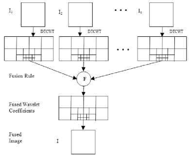
Fig.3. Block diagram of Dual tree complex wavelet transform based image fusion.
Step 2: For both coefficient sets, calculate the threshold for each decomposition level by using (3):
where l is level of decomposition, σ is the standard deviation of DTCWT coefficients. µ and M are mean and median of absolute wavelet coefficients at level l , respectively.
Step 3: For all wavelet coefficients, calculate absolute difference from the corresponding threshold, as below-
D ' ( i . j ) = | Cf ( i . j )| - Ц ( i . j )| (6)
D 2( i . j ) = \Cf 2 ( i . j )| - | Я 2( i . j )| (7)
Step 4: Compare the absolute differences of corresponding coefficients of both the source images and the coefficient having larger value of absolute difference from threshold is selected, to form coefficient set of the fused image.
Cf(i = \Cf' ( i , j )’ if I D 1 ( i , j ) - D 2 ( i , j ) fe'i Cf ( i , j ) { Cf , ( i , j ), if D 2 ( i , j ) >| D ' ( i , j ) (8)
Step 5: Finally, apply inverse dual tree complex wavelet transform on the fused coefficient set to obtain the final fused image.
Cf ( i , j )
InverseDTCWT > Im( i , j )
-
V. Quantitative Quality Metrics
In image processing applications, it is necessary to perform some quantitative quality measurements [24-25] in addition to visual inspection, because for human visual system it is difficult to observe the small changes or differences in the images. These quantitative quality metrics evaluate different parameters of images that reflect on the quality of image. In the present work, we have used six quantitative quality metrics that are standard deviation, mutual information, edge strength, fusion factor, sharpness and average gradient.
-
A. Standard Deviation
Standard deviation is a measure that represents variation or dispersion of image intensity from the mean value. Large variation from the mean values is the key feature of edges, lines and curves that are salient features of an image. Hence, high value of standard deviation is desired for good quality image. The mathematical formula to compute standard deviation is as below:
■ ■ J . :Ё i: (I( i . j ) - д ) 2 (10)
where I(i, j) is the intensity at position (i, j) and µ is the mean intensity of the image. M X N is the size of image.
-
B. Mutual Information
In information theory, mutual information represents the dependence of one variable on other. It measures the amount of information transferred from the source image to the fused image. The amount of information that are transferred from the source images A and B to the fused image F (say IFA and IFB) are:
preservation values of both the source images and it is defined as
I fa ( F , A ) = £ p ( F , A ) log p FFA ( F , A )
F , A pF ( F ) pA ( A )
S F iE M Q AF ( x , y ) ® A ( x , y )+ QBF ( x , y ) m B ( x , y ) (17)
S F = 1 S M = 1 ( ^ A ( x , y ) + ^ ( x , y ) )
I fb ( F , B ) = X P fb ( F , B )log p F "; , ' (12)
F ,B pF ( F ) pB ( B )
Then, the mutual information is expressed as:
M FA = I fa ( F , A) + I fb (F , B ) (13)
where ωA(x,y) and ωB(x,y) are the weights. The value of
QF lies between 0 and 1. Value ‘0’ means total loss of
AB edge information and value ‘1’ indicates full presence of edges.
D. Sharpness
Sharpness measures the small details of an image. High value of sharpness is required for better fusion result. It is defined as:
where, I FA is the amount of information transferred from the source image A to the fused image F and I FB is the amount of information transferred from the source image B to the fused image F . The higher is the mutual information, the more information the fused image has.
C . Edge Strength ( Q A F B )
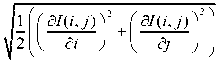
Edges and curves are important features of an image. Quality of an image depends on the quality of its edges. Edge strength measures the quality of edges that are transferred to the fused image from the source images. The higher the value of edge strength is, the better quality fused image is obtained. For calculating the edge strength, firstly, we calculate edge magnitude g(x,y) and orientation a (x, y) e [0, n] for each pixel of image, using Sobel edge operator and then, the relative strength G AF (x,y) and orientation Ф AF ( x , y ) value of source image with respect to fused image. They are defined as:
SP = 1 у ^ 7 ( / , j ) - I ( / , j - i)) 2 + ( 7 ( / , j ) - I ( / - i, j )) 2
MN -^-e 2
where I(i,j) is the intensity at position (i, j) and M X N is the size of image.
E. Average Gradient
It represents the clarity of an image. Higher the value of average gradient, the better is the image quality. Average gradient is defined as below:
1 M - 1 N - 1
AG =------- E E
( M - 1)( N - 1) E E
where I is the source image of size M X N .
GAF ( x , y )
g F ( x ’ У ) if g F ( x , У ) > g A ( x , У ) gA ( x , y )
gA ( x , y ) gF ( x , y )
otherwise
and
ф AF ( xy ) = 1 - I « A ( x , У ) - « F ( x , У )l (15)
, n /2
Now define, QAF, which describes the amount of edge information of image A , preserved in the fused image F . Mathematically, it is the product of a sigmoid mapping function of the relative strength and orientation values, i.e.,
QA ( x , y =
( 1 + e ^ g ( g a ( xy )-
ΓΓ gα )
) ) + (1 + eK - (ф AF ( x ' y )-T- ) )
where K, σ and τ are constants. Values of these constants decide the shape of sigmoid mapping. The edge strength Q F of the fused image is the weighted normalized edge
VI. Experimental Results and Analysis
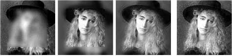
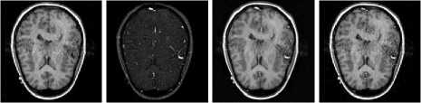
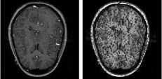
This section presents visual and quantitative results of the proposed method and the other state-of-the-art methods (PCA [26], sharp fusion [27], linear fusion [28], LP [29], DWT [30], SWT [31], LWT [32], MWT [15], Cvt [34], CT [14] and NSCT [33]) as well as comparison of the proposed method with them. We have performed experiments with several set of images, but for demonstration purpose, here, we present results for four set of images. The image set contains two set of multifocus images (one set is multifocus face images and other set is multifocus plane images), one set of remote sensing image and one set of medical image. Size of all images is 256 X 256. Multifocus images contain two objects, one is focused and another is out of focus. The remote sensing images contain two images of different bands. Images of different bands capture different features of earth. In medical images, the first image is T1-weighted MRI image and the second is MRA image. Process of image fusion combines complementary information of the source images into a single image. For fusion of images, the source images must be registered otherwise, their fusion may generate inaccurate results. In
the present work, we have taken source images that are already registered, as image registration is beyond the scope of present work.
(e) (f) (g) (h)
(i)
(l)
(l)
(i)
(m) (n)
(j)
(m)
(k)
(n)
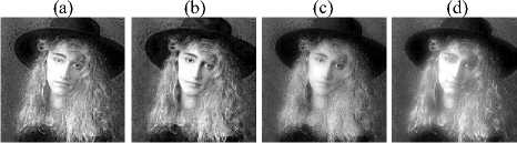
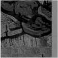
Fig.4. Fusion results for first set of images. (a) source image 1, (b) source image 2, Fused Image by -(c) the proposed method, (d) CvT [34], (e) NSCT [33], (f) CT [14], (g) SWT [31], (h) DWT [30], (i) LWT [32], (j) MWT [15], (k) LP [29], (l) PCA [26], (m) linear fusion [28], (n) sharp fusion [27].
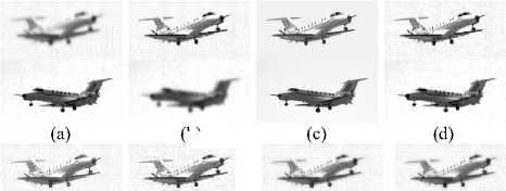
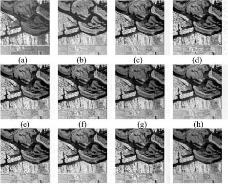
Fig.6. Fusion results for remote sensing images. (a) source image 1, (b) source image 2, Fused Image by -(c) the proposed method, (d) CvT [34], (e) NSCT [33], (f) CT [14], (g) SWT [31], (h) DWT [30], (i) LWT [32], (j) MWT [15], (k) LP [29], (l) PCA [26], (m) linear fusion [28], (n) sharp fusion [27].
(b)
(a) (b) (c) (d)
(f)

(e)
(i)
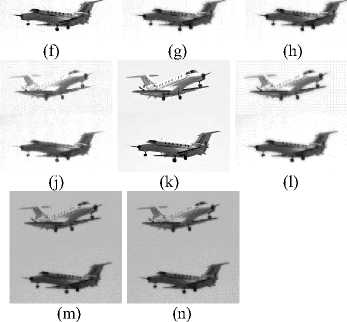
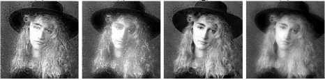
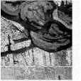
Fig.5. Fusion results for second set of images. (a) source image 1, (b) source image 2, Fused Image by -(c) the proposed method, (d) CvT [34], (e) NSCT [33], (f) CT [14], (g) SWT [31], (h) DWT [30], (i) LWT [32] , (j) MWT [15], (k) LP [29], (l) PCA [26], (m) linear fusion [28], (n) sharp fusion [27].
(i)
(j) (k) (l)
(m) (n)
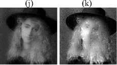
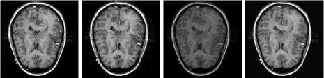
Fig.7. Fusion results for medical images. (a) source image 1, (b) source image 2, Fused Image by -(c) the proposed method, (d) CvT [34], (e) NSCT [33], (f) CT [14], (g) SWT [31], (h) DWT [30], (i) LWT [32], (j) MWT [15], (k) LP [29], (l) PCA [26], (m) linear fusion [28], (n) sharp fusion [27].
In spatial domain methods, the proposed method is compared with principal component analysis [26], sharp fusion [27] and linear fusion [28] based methods and in transform domain methods, the proposed method is compared with Laplacian pyramid [29], discrete wavelet transform [30], stationary wavelet transform [31], lifting
wavelet transform [32] and multiwavelet transform [15] based fusion methods. Apart from wavelet domain methods, we have also compared the proposed method with some new generation wavelet based methods that are highly directional like contourlet transform [14], nonsubsampled contourlet transform [33] and curvelet transform [34] based methods. Visual results of the proposed and other methods [14, 15, 26-34] are shown in the Figs. 4-7. Observing these figures, we can clearly find that the fused images obtained by all spatial domain methods (PCA [26], sharp fusion [27] and linear fusion [28]) are of poor visual quality. Spatial domain fusion methods work directly on the image pixels. Hence, they suffer from loss of information and spiking like effects. Next, the proposed method is compared with transform domain fusion methods (LP [29], DWT [30], SWT [31], LWT [32], MWT [15], Cvt [34], CT [14] and NSCT [33]) and we found that the quality of images of the proposed method is better than the wavelet and advanced wavelet based methods. In few cases, quality of compared methods appears quite similar to that of the proposed method. To distinguish these similarities, some quantitative image quality measurements have been used, as described in section 5 of this paper. On the basis of these quantitative measurements, we can better judge image fusion methods along with the visual results. In the present work, we have used six image quality metrics that are standard deviation, mutual information, edge strength, fusion factor, sharpness and average gradient. Quantitative results of the proposed and other methods have been shown in the tables 1-4 for four representative set of images. In all these tables the proposed method has clearly better results than all the spatial domain methods (PCA [26], sharp fusion [27] and linear fusion [28]) for all the measurements, except for one or two values. Hence, we can say that the proposed method outperforms the spatial domain methods. Next, we have compared the proposed method with wavelet and new generation wavelet based methods. Observing the tables, again we have found that in most of the cases, the proposed method has better performance than these methods [(PCA [26], sharp fusion [27], linear fusion [28], LP [29], DWT [30], SWT [31], LWT [32], MWT [15], Cvt [34], CT [14] and NSCT [33])]. Hence, we can say that the proposed method outperforms all the other methods [(PCA [26], sharp fusion [27], linear fusion [28], LP [29], DWT [30], SWT [31], LWT [32], MWT [15], Cvt [34], CT [14] and NSCT [33])].
Table 1. Quantitative results for first set of image.
|
Methods |
Standard Deviation |
Mutual Information |
F Q AB |
Fusion Factor |
Sharpness |
Average Gradient |
|
The Proposed Method |
63.010164 |
5.814847 |
0.794095 |
5.804351 |
17.821078 |
17.121275 |
|
CvT [34] |
62.090176 |
4.874921 |
0.745262 |
4.840866 |
17.794721 |
17.102386 |
|
NSCT [33] |
61.764404 |
5.281828 |
0.755516 |
5.195534 |
17.731097 |
17.025707 |
|
CT [14] |
62.094746 |
4.519857 |
0.669701 |
4.478571 |
17.857485 |
17.154584 |
|
SWT [31] |
57.944056 |
4.697522 |
0.628612 |
4.647490 |
16.039255 |
15.435943 |
|
DWT [30] |
61.020999 |
5.935462 |
0.543208 |
5.937593 |
16.924965 |
16.273439 |
|
LWT [32] |
61.689785 |
5.041480 |
0.722643 |
4.903114 |
17.891841 |
17.186455 |
|
MWT [15] |
61.053648 |
5.066206 |
0.527577 |
4.929853 |
17.005341 |
16.366358 |
|
LP [29] |
62.851445 |
5.361154 |
0.788554 |
5.366905 |
17.982492 |
17.271821 |
|
PCA [26] |
56.649110 |
4.887105 |
0.465979 |
4.905540 |
9.173017 |
8.809713 |
|
Linear[28] |
0.263782 |
0.564604 |
0.000204 |
4.900398 |
0.024995 |
0.024001 |
|
Sharp [27] |
58.412209 |
8.575634 |
0.502371 |
8.577676 |
12.816281 |
12.248031 |
Table 2. Quantitative results for second set of image.
|
Methods |
Standard Deviation |
Mutual Information |
F AB |
Fusion Factor |
Sharpness |
Average Gradient |
|
The Proposed Method |
79.779885 |
3.530678 |
0.587137 |
2.975106 |
18.652322 |
17.868592 |
|
CvT [34] |
74.362889 |
3.526280 |
0.525842 |
2.946847 |
18.609403 |
17.798978 |
|
NSCT [33] |
75.399183 |
3.919902 |
0.598387 |
3.277344 |
19.161030 |
18.328579 |
|
CT [14] |
76.231797 |
3.194168 |
0.489839 |
2.679872 |
20.643190 |
19.752488 |
|
SWT [31] |
72.700358 |
4.172533 |
0.570625 |
3.482402 |
17.447780 |
16.711169 |
|
DWT [30] |
74.397134 |
4.538647 |
0.530226 |
3.773829 |
19.214430 |
18.417855 |
|
LWT [32] |
76.722388 |
3.630326 |
0.550422 |
3.023507 |
20.386584 |
19.513851 |
|
MWT [15] |
74.517399 |
4.121794 |
0.524027 |
3.617981 |
19.412139 |
18.614656 |
|
LP [29] |
77.560326 |
3.317428 |
0.557169 |
2.783480 |
19.932100 |
19.060556 |
|
PCA [26] |
71.551191 |
6.116748 |
0.556126 |
4.337382 |
13.049841 |
12.490356 |
|
LINEAR [28] |
0.316172 |
1.002703 |
0.000185 |
4.321764 |
0.027915 |
0.026719 |
|
SHARP [27] |
74.552405 |
5.969254 |
0.513791 |
4.751257 |
18.204664 |
17.280266 |
Table 3. Quantitative results for remote sensing image
|
Methods |
Standard Deviation |
Mutual Information |
F Q AB |
Fusion Factor |
Sharpness |
Average Gradient |
|
The Proposed Method |
67.563717 |
4.213773 |
0.599438 |
4.624093 |
9.143359 |
8.913236 |
|
CvT [34] |
65.084267 |
3.763801 |
0.543092 |
3.722547 |
8.898544 |
8.647521 |
|
NSCT [33] |
67.516315 |
4.469523 |
0.623846 |
4.375124 |
9.325269 |
9.084947 |
|
CT [14] |
66.464638 |
3.563856 |
0.487190 |
3.520797 |
10.471154 |
10.173428 |
|
SWT [31] |
44.022285 |
4.092046 |
0.511997 |
4.120302 |
6.654302 |
6.450173 |
|
DWT [30] |
67.699654 |
4.131452 |
0.580549 |
4.149618 |
9.761217 |
9.478859 |
|
LWT [32] |
67.865454 |
4.185036 |
0.579072 |
4.096346 |
9.717206 |
9.460907 |
|
MWT [15] |
67.636215 |
4.742255 |
0.637334 |
4.753151 |
9.470049 |
9.198334 |
|
LP [29] |
67.643440 |
4.069779 |
0.590535 |
4.095415 |
9.498035 |
9.236607 |
|
PCA [26] |
56.574647 |
5.214820 |
0.654891 |
5.248583 |
6.833020 |
6.677453 |
|
LINEAR [28] |
0.160181 |
0.245054 |
0.000187 |
4.050926 |
0.021713 |
0.021149 |
|
SHARP [27] |
61.707860 |
6.666746 |
0.455984 |
6.671616 |
16.298692 |
15.561676 |
Table 4. Quantitative results for medical image.
|
Methods |
Standard Deviation |
Mutual Information |
F Q AB |
Fusion Factor |
Sharpness |
Average Gradient |
|
The Proposed Method |
57.020305 |
5.449373 |
0.795731 |
5.354755 |
3.937842 |
3.836249 |
|
CvT [34] |
56.232863 |
4.736555 |
0.775739 |
4.879745 |
3.954514 |
3.852480 |
|
NSCT [33] |
51.575605 |
4.764215 |
0.761013 |
4.658524 |
3.775885 |
3.671319 |
|
CT [14] |
54.600250 |
3.036701 |
0.728591 |
3.084171 |
4.553882 |
4.430000 |
|
SWT [31] |
52.173647 |
5.052094 |
0.693773 |
7.244782 |
2.979448 |
2.895216 |
|
DWT [30] |
47.954772 |
5.085900 |
0.568923 |
5.088373 |
3.426532 |
3.323157 |
|
LWT [32] |
51.866111 |
4.625440 |
0.738551 |
6.023500 |
3.971291 |
3.866366 |
|
MWT [15] |
47.998410 |
5.072778 |
0.550611 |
4.934643 |
3.480478 |
3.385691 |
|
LP [29] |
56.233728 |
4.402115 |
0.784064 |
4.404088 |
3.936147 |
3.828740 |
|
PCA [26] |
51.875889 |
5.212912 |
0.638550 |
7.609695 |
2.241118 |
2.188089 |
|
LINEAR [28] |
0.342495 |
1.066462 |
0.000406 |
7.647025 |
0.006763 |
0.006603 |
|
SHARP [27] |
53.509806 |
6.551319 |
0.611174 |
6.557366 |
3.192202 |
3.097669 |
-
VII. Conclusions
In this work, we have proposed a new threshold based image fusion method using dual tree complex wavelet transform. The proposed fusion is based on a level dependent threshold that depends on standard deviation of wavelet coefficients, mean and median of absolute wavelet coefficients and decomposition level. Absolute difference of each coefficient from the threshold value is used as a fusion criterion. The proposed fusion rule works because the value of absolute difference from the threshold represents variation in intensity. Hence, large value of absolute difference means more intensity variations (represents curves and edges that are salient features of images). Further, good directionality, approximate shift-invariance, phase information and computational efficiency of dual tree complex wavelet transform make the algorithm more powerful. The proposed method has been compared with several spatial and transform domain fusion methods, in term of both visual perception and quantitative measurements using six standard metrics (standard deviation, mutual information, edge strength, fusion factor, sharpness and average gradient). Visual and quantitative results demonstrate that the proposed method is better than the other methods. The proposed fusion method is tested for multi-focus, medical and remote sensing images. This indicates that the proposed method is effective for different applications.
References Threshold based Image Fusion in Dual Tree Complex Wavelet Domain
- Y. Liu, S. Liu and Z. Wang, "A general framework for image fusion based on multi-scale transform and sparse representation," Information fusion, vol. 24, pp. 147-164, 2015.
- V. Aslantas and A. N. Toprak, "A pixel based multi-focus image fusion method," Optics Communications, vol. 332, pp. 350-358, 2014.
- R. Singh and A. Khare, "Fusion of multimodal medical images using daubechies complex wavelet transform -A
- multiresolution approach", Information fusion, vol. 19, pp. 49-60, 2014.
- R. Srivastava, R. Singh and A. Khare, "Fusion of multifocus noisy images using contourlet transform," Proc. 6th Int. Conf. Contemporary Computing, Noida, India, pp. 497-502, August 2013.
- V.P.S. Naidu and J.R. Raol, "Pixel-level image fusion using wavelets and principal component analysis," Defence Science Journal,vol. 58, pp. 338–352, 2008.
- C. He, Q, Liu, H. Li and H. Li, "Multimodal medical image fusion based on IHS and PCA," Procedia Engineering, vol. 7, pp. 280-285, 2010.
- A. A. Suraj, M. Francis, T.S. Kavya and T. M. Nirmal, "Discrete wavelet transform based image fusion and de- noising in FPGA," Journal of Electrical System and Information Technology, vol. 1, pp. 72-81, 2014.
- S. Li, "Multisensor remote sensing image fusion using stationary wavelet transform: effects of basis and decomposition level," International journal of wavelets, Multiresolution and Information Processing, vol. 6, pp. 37-50, 2008.
- J. J. Lewis, R. J. O'Callaghan, S. G. Nikolov, D. R. Bull and N Canagarajah, "Pixel- and Region-based image fusion with complex wavelets," Information Fusion, vol. 8, pp. 119-130, 2007.
- P.J. Burt, "A gradient pyramid basis for pattern selective image fusion," SID Technical Digest, vol. 16, pp. 467-470, 1985.
- H. Li, B. S. Manjunath and S. K. Mitra, "Multisensor Image fusion using wavelet transform," Graphics Models and Image Processing, vol. 57, 235-245, 1995.
- R. Vijayarajan and S. Muttan, "Discrete wavelet transform based principal component averaging fusion for medical images," AEU-International Journal of Electronics and Communications, vol. 69, pp. 896-902, 2015.
- N. Kingsbury, "The dual-tree complex wavelet transform: a new technique for shift invariance and directional filters," IEEE Digital Signal Processing Workshop, vol. 86, 1998.
- R. Srivastava and A. Khare, "Multifocus noisy image fusion using contourlet transform," The Imaging Science Journal, vol. 63, pp. 408-422, 2015.
- Y. Liu, J. Yang and J. Sun, "PET/CT medical image fusion algorithm based on multiwavelet transform," Proc. 2nd Int. Conf. Advanced Computer Control (ICACC) 2, Shenyang, pp. 264–268, March 2010.
- P.J. Burt and R.J. Kolczynski, "Enhanced Image Capture Through Fusion," Proc. 4th Int. Conf Computer Vision, Berlin, pp. 173-182, May 1993.
- H. LU, X. HU, L. Zhang, S. Yang and S. Serikawa, "Local energy based image fusion in sharp frequency localized contourlet transform," Journal of Computational Information System, vol. 6, pp. 3997-4005, 2010.
- Y. Yang, S. Tong, S. Huang and P. Lin, "Log-Gabor energy based multimodal medical image fusion in NSCT domain," Computational and Mathematical Methods in Medicine, pp.1-12, 2014.
- T. A. Wilson, S.K. Rogers and L.R. Myers, "Perceptual based hyperspectral image fusion using multiresolution analysis," Optical Engineering, vol. 34, pp. 3154-3164, 1995.
- Q. Zhang and B. Guo, "Multifocus image fusion using the nonsubsampled contourlet transform," Signal Processing, vol. 89, pp. 1334–1346, 2009.
- A. Khare, U. S. Tiwari and M. Jeon, "Daubechies complex wavelet transform based multilevel shrinkage for deblurring of medical images in presence of noise," International Journal on Wavelets, Multiresoultion and Information Processing, vol. 7, pp. 587-604, 2009.
- J. Nunez, X. Otazu, O. Fors and A. Prades, "Multiresolution-based image fusion with additive wavelet decomposition," IEEE Transaction on Geoscience and Remote Science, vol. 37, pp. 1204-1211, 1999.
- I. W. Selesnick, R. G. Baraniuk, and N. G. Kingsbury, "The dual-tree complex wavelet transform," IEEE Signal Processing Magazine, vol. 22 , pp. 123-151, 2005.
- S. Li, Z. Li and J. Gong, "Multivariate statistical analysis of measure for assessing the quality of image fusion," International Journal of Image and Data Fusion, vol. 1, pp. 47-66, 2010.
- K. Kotwal and S. Chaudhuri, "A novel approach to quantitative evaluation of hyperspectral image fusion techniques," Information Fusion, vol. 14, pp. 5–18, 2013.
- T. Wan, C. Zhu and Z. Qin, "Multifocus image fusion based on robust principal component analysis," Pattern Recognition Letters, vol. 34, pp. 1001-1008, 2013.
- J. Tian, L. Chen, L. Ma and W. Yu., "Multi-focus image fusion using a bilateral gradient-based sharpness criterion," Optics Communication, vol. 284, pp. 80-87, 2011.
- J.G.P.W. Clevers and R. Zurita-Milla, "Multisensor and multiresolution image fusion using the linear mixing model," in Image Fusion: Algorithms and Applications, T. Stathaki, Ed. Academic Press, Elsevier, 2008, pp. 67–84.
- W. Wang and F. Chang, "A Multi-focus Image Fusion Method Based on Laplacian Pyramid," Journal of Computers, vol. 6, pp. 2559-2566, 2011.
- A. Deng, J. Wu and S. Yang, "An image fusion algorithm based on discrete wavelet transform and Canny operator", Proc. Int. conf. advance research on computer education, simulation and modeling, Wuhan, China, pp. 32-38, June 2011.
- R. Singh, M. Vatsa and A. Noore, "Multimodal medical image fusion using redundant wavelet transform," Proc. 7th Int. Conf. Advances in Pattern Recognition, Kolkata, India, pp. 232–235, February 2009.
- S. Kore and U.S. Tiwari, "Feature level fusion of multimodal medical images in lifting wavelet transform domain," Proc. 26th Annual Int. Conf. IEEE Engineering in Medicine and Biology Society, pp. 1479-1482, September 2004.
- R. Srivastava, R. Singh and A. Khare, "Image fusion based on nonsubsampled contourlet transform," Proc. Int. Conf. Informatics, Electronics & Vision, Dhaka, Bangladesh, pp. 263-266, May 2012.
- R. Srivastava, O. Prakash and A. Khare, "Local energy based multimodal medical image fusion in curvelet domain," IET Computer Vision, doi: 10.1049/iet-cvi.2015.0251.
