Tight focusing of laser light using a surface plasmon polariton in a silver nano-strip and nano-ring on silica glass

Author: Kozlova Elena Sergeevna, Kotlyar Victor Victorovich
Journal: Компьютерная оптика @computer-optics
Section: Opto-it
Article in issue: 5 т.40, 2016.
Free access
In this work a solitary surface plasmon-polariton was obtained by using a frequency-dependent finite difference time-domain method for the TM- and radially polarized light at 532 nm, which was propagated through silver nano-elements (a nano-strip and a nano-ring), placed in an aqueous medium. The device's height and width were equal to 20 nm and 215 nm respectively. The intensity of surface plasmon-polariton was four times higher than that of the incident radiation. The full width at half maximum of the nanojet was 138 nm and 158 nm for the case of using a nano-strip and a nano-ring respectively. The results can be used to design devices that allow capturing and moving particles in water or other biofluids.
Surface plasmon polaritons, nano-strip, nano-ring, fdtd-method, tight focusing, nanojet
Short address: https://sciup.org/14059599
IDR: 14059599 | DOI: 10.18287/2412-6179-2016-40-5-629-634
Text of the scientific article Tight focusing of laser light using a surface plasmon polariton in a silver nano-strip and nano-ring on silica glass
Today great attention is paid to such optical phenomena as surface plasmon-polaritons (SPPs) which arise during interaction of light with the metal and propagate along the interfaces between metal and dielectric [1 –3]. SPP can be widely used to solve various problems of modern science and technology [4– 8]. The plasmonic field represents an exciting new area for the application of SPPs in which surface-plasmon based circuits merge the fields of photonics and electronics at the nanoscale [9]. The SPPs can serve as a basis for constructing nanoscale photonic circuits that will be able to carry optical signals and electric currents [10, 11]. SPPs can also serve as a basis for the design, fabrication and characterization of subwavelength waveguide components [12– 15]. In the framework of plasmonics, modulators and switches have also been investigated [16, 17], as well as the use of SPPs as mediators in the transfer of energy from donor to acceptors molecules on opposite sides of metal films [18]. Application of SPPs enables subwavelength optics in microscopy and lithography beyond the diffraction limit [19, 20]. It also enables the first steady-state micromechanical measurement of a fundamental property of light itself: the momentum of a photon in a dielectric medium. Other applications are photonic data storage [21] and light generation [22].
A large number of works devoted to the modeling of nano-antennas, based on SPP's excitation effect [23, 24]. A Fabry-Perot model was formulated that predicts both the peak position and spectral shape of optical resonances for short-range SPP. The authors used full-field simulation based on the finite-difference time-domain method (FDTD-method) to calculate the parameters for this model [23]. Whereas, some other authors used rectangular gold and silver nano-strips embedded in glass or water. The effect of SPP's resonance is analyzed using a surface integral equation method. They showed the feasibility of at least 10-fold field magnitude enhancement for local field in narrow (5 nm) gap between two metal strips [24]. But all these authors didn't investigate another properties of SPP like length and full width at half maximum (FWHM).
In our previous work we have investigated the amplitude Fresnel zone plate for focusing of laser light. During this study we have found SPP's on surface of silver relief of this zone plate [25]. In this paper, we used the frequency-dependent FDTD-method ((FD)2TD-method) for investigating the process of SPP's formation on silver nanostrip for the incident TM-polarized light at 532 nm. We estimated spatial characteristics such as length and FWHM of SPPs which is new investigation up to our knowledge. We also used the (FD)2TD-method for investigating the process of SPP's formation on silver nanoring for the incident radial-polarized light at 532 nm. The estimation of spatial characteristics such as length and FWHM of SPPs also was carried out. In contrast to the works described above, silver elements (nano-strip and nano-ring) are placed on a silica glass, which has a high influence on the process of SPP's formation.
Formation of SPPs on silver nano-strip
We considered the propagation of a TM-polarized light at 532 nm, which was normally incident on the metal nanostrip placed on a substrate. The optical scheme is presented on Fig. 1. Height and width of nano-strip are h and w respectively. The permittivity of the medium, nano-strip and substrate are ε1, εm and ε2 respectively. The light is propagating along Z axis. All the simulations were carried out by FullWAVE (RSoft) based on (FD)2TD-method. Hereinafter, the following simulation parameters were used: spatial steps were 2 nm, time step was 1 nm (ct, where c is speed of light in vacuum, t is a time).
ZA
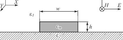
Fig. 1. Optical scheme for nano-strip
Silica glass was considered as a material of substrate. Table 1 shows parameters for the Sellmeier's permittivity model of silica glass [26]:
ε 2
( λ ) =ε ∞ + ∑ m
∆ε m λ 2 λ 2 -λ 2 m - i λη m ,
where λ is a wavelength; ε ∞ ( x, z ) is the permittivity in the limit of infinite frequency; Δε m is the resonance strength; λ m is the resonant wavelength; η m is the Sellmeier damping factor.
Table 1. Parameters for the Sellmeier's permittivity model of silica glass
|
m |
Δε m |
λ m , µ m |
η m , µ m |
|
1 |
0.69616630 |
0.068404300 |
0 |
|
2 |
0.40794260 |
0.11624140 |
0 |
|
3 |
0.89747940 |
9.8961610 |
0 |
|
ε ∞ = 1 |
|||
Silver was considered as a material of nano-strip. Table 2 shows parameters for the Drude-Lorentz's permittivity model of silver [27]:
ε m ( ω ) =ε∞+ ( ω 2 p /( - 2 i ων-ω 2 )) + + ∑ ( A m ω 2 m /( -ω 2 - 2 i ωδ m +ω m 2 )), m
where ω is a frequency; ω p is the plasma frequency; ν is the collision frequency; A m is the resonance strength; δ m is the damping factor; ω m is the resonant frequency.
Table 2. Parameters for the Drude-Lorentz's permittivity model of silver
|
m |
A m |
δ m , , Hz |
ω m , Hz |
|
1 |
7.924697 |
19.68071 |
4.132646 |
|
2 |
0.501327 |
2.289161 |
22.6941 |
|
3 |
0.013329 |
0.329194 |
41.45307 |
|
4 |
0.826552 |
4.639097 |
46.001 |
|
5 |
1.113336 |
12.25 |
102.759 |
|
ε ∞ =1 |
|||
|
ω p =41.94605 Hz |
|||
|
ν =0.243097 Hz |
|||
For the first series of simulation we fixed the strip height equals to h =20 nm, remove the substrate and choose air ( ε 1 = 1) as a medium. After each calculation, we measured the maximum intensity of light at 2 nm above the nano-strip. Fig. 2 shows the SPP's intensity dependence on nano-strip width. These results are consistent with the results of other authors in similar calculations which have been carried out for nano-strips with other dimensions (thickness and width) [23, 24].
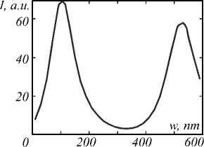
Fig. 2. The SPP's intensity dependence on nano-stip width for incident light at 532 nm
By comparing the simulation results for light propagation through the silver nano-strip of various widths, the resonant width w = 110 nm has been selected. Nano-strip with this width forms a “boundary” SPPs with the highest value of the intensity in the central peak. Fig. 3 shows the intensity distribution obtained at 2 nm above silver nanostrip with width of w = 110 nm.
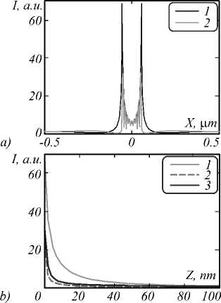
Fig. 3. (a) Intensity distribution at 2 nm above silver nano-strip of width , w = 110 nm placed in air (line 1) and on the silica glass placed in water (line 2). (b) SPP's intensity distribution through the direction of light propagation in the case of using nano-strip placed in air (line 1) and nano-strip on the silica glass placed in air (line 2) and water (line 3)
Two powerful “boundary” SPP (line 1) with high intensity (68 a.u.) and small FWHM (8 nm) can be seen from Fig. 3 a . Fig. 3 b shows the intensity distribution in the SPP along axis of light propagation. Measurement of SPPs “length” showed that the distance of decline to incident intensity through the Z direction is 68 nm, while through the direction of SPPs propagation it is 94 nm (Fig. 3 b , line 1). The inclination angles of straight which were coinciding with the directions of SPPs propagation are 112 ° and 68 ° .
For the next simulations the substrate from silica glass was added. In this case, the direction of SPPs propagation changed and practically coincided with the direction of light propagation (it was parallel to the Z axis). However, the presence of the substrate substantially disrupts the formation of the SPP. It leads to fluctuations at the interface substrate/strip environments, reduces the maximum intensity and “length” till 20 nm (Fig. 3b, line 2) of “boundary” SPPs.
To compensate this effect, water ( ε 1 = 1.78) was chosen as a main medium instead of air. In this case measurement of SPPs “length” showed that the distance of decline to incident intensity through the Z direction is 56 nm (Fig. 3 b , line 3). FWHM of “boundary” SPPs is 75 nm (Fig. 3 a , line 2). The intensity of “boundary” SPPs is 36 times higher than intensity of incident light (Fig. 3 a , line 2). However, the use of such sharply focused light is complicated by the close proximity of these peaks to each other and the presence of the boundary plasmonic lobes, which are formed along the entire nano-strip.
In addition to “boundary” short-range SPPs which have a maximum intensity, there are other SPPs. However, during the study of dependences of SPP's intensity distribution on the width of nano-strip placed in the air shows no possibility to obtain a “long” single SPP in the center of nano-strip. A similar study for the nano-strip placed on the silica glass in an aqueous medium revealed the presence of this “central” SPP. By comparing the simulation results for light propagation through the silver nano-strip of various widths, the width w =215 nm has been selected. Fig. 4 shows the intensity distribution at 6 nm above silver nano-strip with width of w = 215 nm.
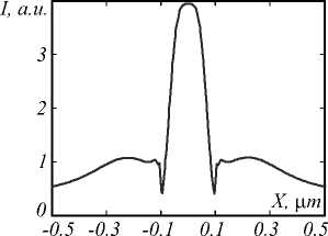
Fig. 4. Intensity distribution 6 nm after silver nano-strip with width of w = 215 nm o silica glass in water
Fig. 4 shows that the “boundary” SPPs is almost completely absent. FWHM of “central” SPP is 138 nm. The intensity of “central” SPP is four times higher than intensity of incident light (Fig. 4). The measurement of SPP “length” showed that the decay length to incident intensity through Z direction is 54 nm. The “central” SPP is also observed on the silver nano-strip with width of w = 215 nm placed on silica glass in air, but “boundary” SPPs are also present and their intensity is comparable with the intensity of “central” SPP.
Formation of SPPs between silver nano-srips
In this part we considered the propagation of a TM-polarized light at 532 nm, which was normally incident on the gap between two metal nano-strips placed on a substrate. The optical scheme is presented on Fig. 5. Height and width of nano-strips are h and w respectively. The width of the gap is w h . The light is propagating along Z axis.
The height of nano-srtips was fixed at 10 nm as in [24]. By comparing the simulation results for light propagation through the gap between two silver nano-strip of various widths, the resonant widths of strips w =55 nm and gap wh =6 nm have been selected. Gap with this width forms a SPPs with the highest value of the intensity in the central peak. Simulations were carried out for both cases in air and in water. Fig. 6 shows the intensity distribution obtained at 2 nm above silver nano-strips.
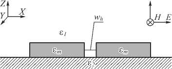
Fig. 5. Optical scheme for two nano-strips
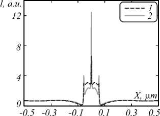
Fig. 6. Intensity distribution at 2 nm above silver nano-strips of width w = 55 nm with gap of 6 nm between them. Strips are on the silica glass placed in air (line 1) or in water (line 2)
Powerful “boundary” SPPs with high intensity (6.2 a.u. in air and 13.3 a.u. in water) and small FWHM (2–3 nm) can be seen from Fig. 6. Unfortunately, measurement of SPPs “length” showed that the distance of decline to incident intensity through the Z direction is near 10 nm. This radiation is “gripped in a vice” of metal strips.
Formation of SPPs on silver nano-ring
In previous part we show the presence of “central” SPP on silver nano-strip with width of 215 nm in aqueous medium. In this part we considered the formation of “central” SPPs on silver nano-ring placed on a substrate. We considered the propagation of light at 532 nm, which was normally incident on the metal nano-ring. The radial polarization is selected to satisfy the condition of formation of SPPs. The optical scheme is presented on Fig. 7. Height of nanoring is h . Width and internal radius (the distance from the centre of symmetry to the center line of the circule) of nano-ring are w c and R respectively. The permittivity of the medium, nano-ring and substrate are ε 1 , ε m and ε 2 respectively. The light is propagating along Z axis. All the simulations were carried out by FullWAVE. Hereinafter, the following simulation parameters were used: steps in space were λ /30 nm, time step was λ /60 nm ( ct ).
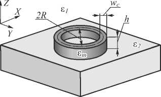
Fig. 7. Optical scheme for nano-ring: light propagates from the bottom up
The incident field was calculated in MATLAB and was set from file into FullWAVE to produce radial polarization. The calculation was carried out by using next equations for each component of the field:
E x
2л/2 • x 8
e
2 2
x 2 + У
<
E y
2V2 • y
2 2
x 2 + У У" e ,
where E x and E y are the components of electric field, δ is the waist of Gaussian beam.
The radius of waist of both Gaussian beams (for E x and E y components) was chosen equal to 0.5 µm and maximum intensity was normed to 1 a.u. Fig. 6 shows the incident light for simulation.
It can be seen from the Fig. 8 that the maximum of input intensity is at the radius of 0.5 µm, so the internal radius R = 0.5 µm is chosen to ensure that the maximum intensity of the radiation fell on the circle.
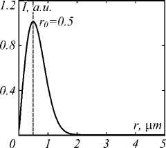
Fig. 8. Input radial polarized light with waist 3 = 0.5 ^m : distribution along the radius r
A similar to previous study for the nano-ring placed on the silica glass in an aqueous medium revealed the presence of this “central” SPP. By comparing the simulation results for light propagation through the silver nano-ring of various widths, the width w =215 nm has also been selected. Fig. 9 shows the intensity distribution at λ / 15 nm above silver nano-ring with width of w =215 nm.
Fig. 9 a shows that the “central” SPP is evenly located on the whole surface of the circle. Fig. 9 b shows that the “boundary” SPPs is almost completely absent. FWHM of “central” SPP is 158 nm. The intensity of “central” SPPs at λ / 15 nm above silver nano-ring is three times higher than intensity of incident light (Fig. 9).
The measurement of SPPs “length” was also carried out. Fig. 10 shows the longitudinal distribution of light (distribution along the Z axis). It shows that the “length” of SPP through Z direction is 100 nm.
Conclusion
In this work the process of SPPs formation on silver nanostrip for TM-polarized light at 532 nm is studied. The spatial characteristics of SPPs like “length” and FWHM were investigated by using (FD)2TD-method. In contrast to the [23, 24], where silver nano-strips were considered to be placed into any media (water or silica glass), we consider them to be placed on a silica glass in air or water. In this case we can use the energy of SPPs for different application as optical tweezers or microscopy while using of scheme from [23, 24] we get this energy in any substrate. Unfortunately the presence of several dielectrics with different values of permittivity in scheme brings a disturbance in the process of SPP's formation. It leads to fluctuations of field of light intensity at the interface sub-strate/strip environments, reduces the maximum intensity and “length” of SPP's. To compensate this effect, the water (£1 = 1.78) was chosen as a main medium instead of air. In this case measurement of SPPs “length” showed that the “length” of SPP through the Z direction is 56 nm (Fig. 3b, line 3). FWHM of “boundary” SPPs is 75 nm (Fig. 3a, line 2). The intensity of “boundary” SPPs is 36 times higher than intensity of incident light (Fig. 3a, line 2).
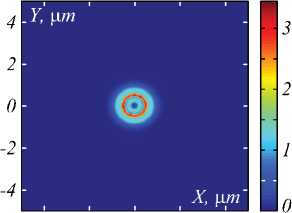
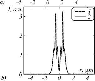
Fig. 9. Intensity distribution λ / 15 nm after silver nano-ring with width of w = 215 nm on the silica glass placed in water: distribution at XY-plane (a) and along the radius r for y= 0.5
(line 1) and x= 0.5 (line 2)
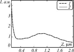
Fig. 10. SPP's intensity distribution through the direction of SPP's propagation in the case of using nano-ring placed on the silica glass in water fixing (x,y) at (0, 0.5) (line 1) and at (0.5,0) (line 2)
Analogous investigation for narrow gap between two nano-strips was carried out. Powerful “boundary” SPPs with high intensity (13.3 a.u. in water) and small FWHM (2–3 nm) was obtained. The intensity of this SPPs is in 1.1 times bigger than the intensity of SPPs in [24] while the nano-strips were considered to be placed on silica glass.
Simulations by (FD)2TD-method showed presence of “central” SPP for silver nano-strip placed in water. FWHM of "central" SPP is 138 nm. The intensity of “central” SPPs is four times higher than the intensity of incident light (Fig. 4). The “boundary” SPPs is almost completely ab- sent. This result was generalized for 3D case for radial polarized light and nano-ring. Simulations by (FD)2TD-method showed presence of “central” SPP for silver nanoring placed on silica glass in water. FWHM of “central” SPP is 158 nm. The intensity of “central” SPPs is four times higher than the intensity of incident light (Fig. 10). The “boundary” SPPs are also almost completely absent. Unlike plasmonic lens with Archimedes spiral slot etched on it [28, 29], a nano-strips and nano-ring are easy to manufacture and also focuses light in a narrower area: the FWHM is 0.26λ (FWHM is 0.35λ in [28, 29]).
Investigation of convergence of solutions was also carried out. Reducing of the dimensions of the grid twice did not lead to significant changes in the results of the simulation. In particular, the FWHM of the focal spot is not changed, and the maximum intensity is slightly decreased.
The results can be used to design devices that allow capturing and moving the particles in water or other biofluidics [30, 31].
References Tight focusing of laser light using a surface plasmon polariton in a silver nano-strip and nano-ring on silica glass
- Bezus, E.A. Phase modulation and refraction of surface plasmon polaritons with parasitic scattering suppression/E.A. Bezus, L.L. Doskolovich//Computer Optics. -2014. -Vol. 38(4). -P. 623-628. - DOI: 10.18287/0134-2452-2014-38-4-623-628
- Bezus, E.A. Low-scattering surface plasmon refraction with isotropic materials/E.A. Bezus, L.L. Doskolovich, N.L. Kazanskiy//Optics Express. -2014. -Vol. 22(11). -P. 13547-13554. - DOI: 10.1364/OE.22.013547
- Soifer, V.A. Diffractive optical elements in nanofotonics devices/V.A. Soifer, V.V. Kotlyar, L.L. Doskolovich//Computer Optics. -2009. -Vol. 33. -P. 352-368. -.
- Kadomina, E.A. Resonant photonic-crystal structures with a diffraction grating for refractive index sensing/E.A. Kadomina, E.A. Bezus, L.L. Doskolovich//Computer Optics. -2016. -Vol. 40(2). -P. 164-172. - DOI: 10.18287/2412-6179-2016-40-2-164-172
- Ma, R.-M. Plasmon lasers: coherent light source at molecular scales/R.-M. Ma, R.F. Oulton, V.J. Sorger, X. Zhang//Laser & Photonics Reviews. -2013. -Vol. 7(1). -P. 1-21. - DOI: 10.1002/lpor.201100040
- Xie, Zh. Plasmonic Nanolithography: A Review/Zh. Xie, W. Yu, T. Wang, H. Zhang, Yo. Fu, H. Liu, F. Li, Zh. Lu, Q. Sun//Plasmonics. -2011. -Vol. 6. -P. 565-580. - DOI: 10.1007/s11468-011-9237-0
- Han, Z. Radiation guiding with surface plasmon polaritons/Z. Han, S.I. Bozhevolnyi//Reports on Progress in Physics. -2013. -Vol. 76(1). -016402. - DOI: 10.1088/0034-4885/76/1/016402
- Atwater, H.A. Plasmonics for improved photovoltaic devices/H.A. Atwater, A. Polman//Nature Materials. -2010. -Vol. 9. -P. 205-213. - DOI: 10.1038/nmat2629
- Ozbay, E. Plasmonics merging photonics and electronics at nanoscale dimentions/E. Ozbay//Science. -2006. -Vol. 311(5758). -P. 189-193. - DOI: 10.1126/science.1114849
- Barnes, W.L. Surface plasmon subwavelength optics/W.L. Barnes, A. Dereux, T.W. Ebbesen//Nature. -2003. -Vol. 424. -P. 824-830. - DOI: 10.1038/nature01937
- Nomura, W. Nanodot coupler with a surface plasmon polariton condenser for optical far/near-field conversion/W. Nomura, M. Ohtsu, T. Yatsui//Applied Physics Letters. -2005. -Vol. 86(18). -181108. - DOI: 10.1063/1.1920419
- Maier, S.A. Experimental demonstration of fiber-accessible metal nanoparticle plasmon waveguides for planar energy guiding and sensing/S.A. Maier, M.D. Friedman, P.E. Barclay, O. Painter//Applied Physics Letters. -2005. -Vol. 86(7). -071103. - DOI: 10.1063/1.1862340
- Berini, P. Characterization of long-range surface-plasmon-polariton waveguides/P. Berini, R. Charbonneau, N. Lahoud, G. Mattiussi//Journal of Applied Physics. -2005. -Vol. 98(4). -043109. - DOI: 10.1063/1.2008385
- Bozhevilnyi, S.I. Channel Plasmon-Polariton Guiding by Subwavelength Metal Grooves/S.I. Bozhevilnyi, V.S. Volkov, E. Devaux, T.W. Ebbesen//Physical Review Letters. -2005. -Vol. 95. -046802. - DOI: 10.1103/PhysRevLett.95.046802
- Bozhevilnyi, S.I. Channel plasmon subwavelength waveguide components including interferometers and ring resonators. S.I. Bozhevilnyi, V.S. Volkov, E. Devaux, J.Y. Laluet, T.W. Ebbesen//Nature. -2006. -Vol. 440. -P. 508-511. - DOI: 10.1038/nature04594
- Krasavin, A.V. Active plasmonics: Controlling signals in Au/Ga waveguide using nanoscale structural transformations/A.V. Krasavin, N.I. Zheludev//Applied Physics Letters. -2004. -Vol. 84(8): -P. 1416-1418. - DOI: 10.1063/1.1650904
- Krasavin, A.V. Active control of surface plasmon-polariton waves/A.V. Krasavin, A.V. Zayats, N.I. Zheludev//Journal of Optics A: Pure and Applied Optics. -2005. -Vol. 7(2). -P. S85. - DOI: 10.1088/1464-4258/7/2/011
- Andrew, P. Energy transfer across a metal film mediated by surface plasmon polaritons/P. Andrew, W.L. Barnes//Science. -2004. -Vol. 306(5698). -P. 1002-1005. - DOI: 10.1126/science.1102992
- Kim, E.S. Surface plasmon-assisted nano-lithography with a perfect contact aluminum mask of a hexagonal dot array/E.S. Kim, Y.M. Kim, K.C. Choi//Plasmonics. -2016. -Vol. 11(5). -P. 1337-1342. - DOI: 10.1007/s11468-016-0180-y
- Luo, X. Surface plasmon resonant interference nanolithography technique/X. Luo, T. Ishihara//Applied Physics Letters. -2004. -Vol. 84(23). -P. 4780-4782. - DOI: 10.1063/1.1760221
- Ditlbacher, H. Spectrally coded optical data storage by metal nanoparticles/H. Ditlbacher, J.R. Krenn, B. Lamprecht, A. Leitner, F.R. Aussenegg//Optics Letters. -2000. -Vol. 25(8). -P. 563-565. - DOI: 10.1364/OL.25.000563
- Kim, S. High-harmonic generation by resonant plasmon field enhancement/S. Kim, J. Jin, Yo.-J. Kim, I.-Yo. Park, Yu. Kim, S.-W. Kim//Nature. -2008. -Vol. 453(7196). -P. 757-760. - DOI: 10.1038/nature07012
- Søndergaard, T. Metal nano-strip optical resonators/T. Søndergaard, S.I. Bozhevolnyi//Optics Express. -2008. -Vol. 15(7). -P. 4198-4204. - DOI: 10.1364/OE.15.004198
- Barnard, E.S. Spectral properties of plasmonic resonator antennas/E.S. Barnard, J.S. White, A. Chandran, M.L. Brongersma//Optics Express. -2008. -Vol. 16(21). -P. 16529-16537. - DOI: 10.1364/OE.16.016529
- Kozlova, E.S. Comparative modeling of amplitude and phase zone plates/E.S. Kozlova, V.V. Kotlyar, A.G. Nalimov//Computer Optics. -2015. -Vol. 39(5). -P. 687-693. - - DOI: 10.18287/0134-2452-2015-39-5-687-693
- Couairon, A. Filamentation and damage in fused silica induced by tightly focused femtosecond laser pulses/A. Couairon, L. Sudrie, M. Franco, B. Prade, A. Mysyrowicz//Physical Review B. -2005. -Vol. 71(12). -P. 125435-125441. - DOI: 10.1103/PhysRevB.71.125435
- Vial, A. A new model of dispersion for metals leading to a more accurate modeling of plasmonic structures using the FDTD method/A. Vial, T. Laroche, M. Dridi, L. Le Cunff//Applied Physics A. -2011. -Vol. 103(3). -P. 849-853. - DOI: 10.1007/s00339-010-6224-9
- Huang, F. Centrally Symmetric Focusing of Surface Plasmon Polaritons with a Rectangular Holes Arrayed Plasmonic Lens/F. Huang, X. Jiang, H. Yuan, S. Li, H. Yang, X. Sun//Plasmonics. -2016. -Vol. 11(6). -P. 1637-1643. - DOI: 10.1007/s11468-016-0220-7
- Liu, J. Focusing surface plasmon and constructing central symmetry of focal field with linearly polarized light/J. Liu, Y. Gao, L. Ran, K. Guo, Z. Lu, S. Liu//Applied Physics Letters. -2015. -Vol. 106. -013116. - DOI: 10.1063/1.4905307
- Porfirev, A.P. Optical trapping and moving of microparticles using asymmetrical bessel-gaussian beams/A.P. Porfirev, A.A. Kovalev, V.V. Kotlyar//Computer Optics. -2016. -Vol. 40(2). -P. 152-157. - - DOI: 10.18287/2412-6179-2016-40-2-152-157
- Porfirev, A.P. Optical capture of microparticles in special traps/A.P. Porfirev, R.V. Skidanov//Computer Optics. -2012. -Vol. 36(2). -P. 211-218. -.
