To the task of controlling a group of objects on the basis of information technologies

Author: Zhalnin D.A.
Journal: Сибирский аэрокосмический журнал @vestnik-sibsau
Section: Информатика, вычислительная техника и управление
Article in issue: 2 т.20, 2019.
Free access
To participate the TPP with cross-section communications in the general primary frequency control, it is necessary to have a working main regulator. The main regulator is designed to maintain the steam pressure in the major steam line of the TPP at a given level, which is a difficult task. At the TPP with cross-connections, the steam produced by the boilers enters the major steam line. To maintain the pressure in the major steam line, it is necessary to control the heat load of the working boilers. Traditional solutions to construct the main regulator found no use, as have a number of disadvantages, not allowing exploiting a system of automatic control. Looking at the steam pressure control system in the major steam line from the bottom to up, it is possible to identify disadvantages that prevent the effective operation of the main regulator at each level. At the lower level of the main regulator, there are controllers of heat load of boilers, built according to the scheme task-heat. Heat load controllers are designed to maintain heat release in the boiler fur- nace at the required level. The heat signal is the sum of the signals for the steam flow of the boiler and the rate of change in the steam pressure in the boiler drum. Such a structure does not allow maintaining the invariance of the heat signal under external disturbances effectively, as sharp changes of the steam pressure in the major steam line lead to a "false" operation of the controllers. At the upper level there is the main regulator itself, which maintains the steam pressure in the major steam line at a given level and corrects the tasks to the controllers of the heat load of the boilers. The simultaneous identical effect on the heat load of the boilers cannot be optimal from the point of view of the criteria for assessing the quality of regulation, since the dynamic properties of the boilers, such as the gain, the transition time constant and the transport delay are individual for each boiler. However, in 2006-2008, the attempt to build an updated main regulator that takes into account the shortcomings of the traditional scheme was made. The basis of the structure of the main regulator is still parametric and, as a result of ten-years’ experience, shortcomings in the operation of the updated main regulator were identified. The shortcomings, in most cases, consist in need of frequent corrections of adjusting coefficients of system because of the change of dynamic properties of an object during the operation. In fact, the same problems related to the parametric structure of the regulator remain. Up-to-date information technologies made it possible to introduce adaptive process control systems that allow to count an extended number of signals entering the system and to form control actions, based on both current and historical data of the technological process. The use of the latest information technologies and modern hardware in the control of complex multi-connected units that solve not only the problems of process control, but also the problem of improving the economic and environmental performance of enterprises, should become a new step in the development of automatic control systems.
Tpp with cross-section connections, main regulator, heat load controller, pressure regulation in the major steam line
Short address: https://sciup.org/148321904
IDR: 148321904 | UDC: 62-533.6 | DOI: 10.31772/2587-6066-2019-20-2-144-152
К задаче управления группой объектов на основе информационных технологий
Для участия тепловых электростанций (ТЭС) с поперечными связями в общем первичном регулировании частоты необходимо наличие работающего главного регулятора. Главный регулятор предназначен для поддержания давления пара в общем паропроводе ТЭС на заданном уровне, что является сложной задачей. На ТЭС с поперечными связями производимый котлами пар поступает в общий паропровод. Для поддержания давления в общем паропроводе необходимо комплексное управление тепловой нагрузкой работающих котлов. Традиционные решения построения главного регулятора не нашли применения, так как имеют ряд недостатков, не позволяющих эксплуатировать такую систему автоматического регулирования. Если рассматривать систему регулирования давления пара в общем паропроводе снизу вверх, можно на каждом уровне выявить недостатки, мешающие эффективной работе главного регулятора. На нижнем уровне главного регулятора расположены регуляторы тепловой нагрузки котлов, построенные по схеме задание - теплота. Регуляторы тепловой нагрузки предназначены для поддержания тепловыделения в топке котла на требуемом уровне. Сигнал по теплоте представляет собой сумму сигналов по расходу пара за котлом и скорости изменения давления пара в барабане котла. Такая структура не позволяет эффективно поддерживать инвариантность сигнала по теплоте при внешних возмущениях, таких как резкое изменение давления пара в общем паропроводе, что приводит к «ложной» работе регуляторов. На верхнем уровне расположен непосредственно сам главный регулятор, поддерживающий давление пара в общем паропроводе на заданном уровне и корректирующий задания регуляторам тепловой нагрузки котлов. Одновременное одинаковое воздействие на тепловую нагрузку котлов не может быть оптимальным с точки зрения критериев оценки качества регулирования, так как динамические свойства котлов, такие как коэффициент усиления, постоянная времени переходного процесса и транспортное запаздывание, индивидуальные для каждого котла. Однако в 2006-2008 гг. была осуществлена попытка построения обновленного главного регулятора, учитывающего недостатки традиционной схемы. Основа структуры главного регулятора по-прежнему осталась параметрической, и в результате десятилетнего опыта эксплуатации были выявлены недочеты в работе обновленного главного регулятора. Недочеты в основном состоят в необходимости частой корректировки настроечных коэффициентов системы из-за изменения динамических свойств объекта в процессе эксплуатации. По сути, остались те же самые проблемы, связанные с параметрической структурой регулятора. С появлением новейших информационных технологий появляется возможность внедрения адаптивных систем управления технологическими процессами, позволяющими обрабатывать расширенное количество поступающих в систему сигналов и формировать управляющие воздействия, основываясь как на текущих, так и на исторических данных технологического процесса. Использование новейших информационных технологий и современных аппаратных средств при управлении сложными многосвязными объектами, решающих не только задачи управления технологическими процессами, но и задачи повышения экономических и экологических показателей предприятий, должно стать новым витком в развитии систем автоматического управления.
Text of the scientific article To the task of controlling a group of objects on the basis of information technologies
Introduction. One of the conditions of participation of thermal power plants (TPP) with cross-section communications in the general primary regulation of frequency (GPRF) is functioning as the main regulator of steam pressure in the major steam line to control the load of the group of boilers participating in GPRF [1]. Traditional automatic control systems (ACS) of the heat load of boilers used at TPP with cross-connection communications are not able to provide the required dynamics of primary power output at a sudden change in frequency, which can be one of the reasons for emergency fan shutdowns in power systems.
Traditional approach. To maintain the steam pressure in the main steam line at the TPP with cross- connection communications, as a rule, a control scheme is used, when one of the boilers, working in the “regulating” mode, maintains the pressure in the main steam line, and the remaining boilers, working in the “basic” mode, support their specified steam loads.
With this control scheme, the automatic change in the total steam load of the station is limited to the range of possible steam loads of the boiler operating in the “regulating” mode, which is usually 70–100 % of the nominal capacity of the boiler.
Such a range of regulation can not provide a change in the electrical power of the station in 10 % of the nominal frequency deviation, which is necessary for the participation of the station in GPRF.
In order to increase the range of regulation in the “regulating” mode, we can include two boilers and more, but then there is an effect of “pumping” loads of boilers. It is caused by different dynamic properties of boiler equipment and the lack of centralized pressure measurement in the major steam pipe, as well as different values for different boilers job. As a result, some boilers are loaded to the maximum, while others are unloaded to a minimum. This approach makes the process of regulation impossible.
Generally accepted structure of the main regulator (MR), which maintains the pressure in the major steam line at a given value [2], in which one correcting regulator influence the task of the heat load controllers (HLC) of several boilers, has not been used at TPP with crossconnection communications for the following practical reasons:
– the pressure extraction point in the major steam line is the one and does not allow to regulate the pressure at different sets of working boilers and turbines effectively, as well as at the withdrawal of sections of the major steam line for repair;
– when changing the set of working boilers requires reconfiguration of the main regulator;
– the values of the setting coefficients of the main regulator for all boilers can not be the same, since the dynamic properties of the cascade regulator “MR-HLC” are different for each boiler.
Attempts to solve. From 2006 to 2008 at Krasnoyarsk TPP-2 of JSC “Yenisei TGC (TGC-13)” the main regulator that resolves a number of shortcomings of the conventional pressure control structure of the main steam line at
TPP with cross-connection communication was implemented [3]. A significant difference between the updated structure of the main regulator is that instead of one corrective regulator acting on a group of boilers, several corrective regulators are used, separately acting on each boiler.
The technological scheme of the major steam line of Krasnoyarsk TPP-2 is shown in fig. 1. It can be seen from the scheme that the boilers can operate both on the main steam line and separately (block). At block inclusion of boiler units or shutdown of any part of the main steam line, it is necessary to maintain constant pressure in in each its separate part.
Before the implementation of the updated main regulator, boilers heat load regulating systems were used under the scheme of task-heat (fig. 2). The “heat” signal is formed from two signals: steam flow rate and pressure change rate in the boiler drum. The main disadvantage of such a structure of the regulator is that when the pressure in the main steam line (external disturbances) changes, the pressure in the boiler drum changes with a significant delay caused by the capacitive properties of the steam path “drum – steam super heater – steam chamber – main steam line”. This effect makes it impossible to achieve invariance of the signal by “heat” to external disturbances.
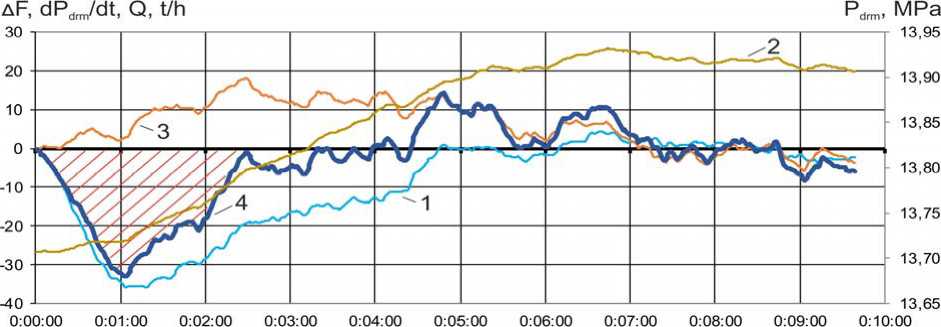
Fig. 3 shows the steam flow rate of the boiler, the steam pressure in the boiler drum, the reduced rate of change in the steam pressure in the boiler drum and the change in the reduced signal by “heat” with the pressure increase in the major steam line by 0.3 MPa (external perturbation).
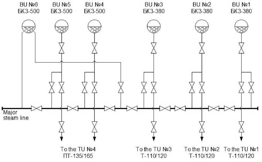
Fig. 1. Major steam line layout of the Krasnoyarsk TPP-2: BU – boiler unit; TU – turbo unit
Рис. 1. Схема общего паропровода Красноярской ТЭЦ-2: КА – котлоагрегат; ТА – турбоагрегат
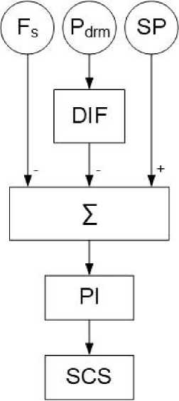
Fig. 2. Structural scheme of the heat load controller:
F s – steam flow sensor behind the boiler; P drm – boiler drum steam pressure sensor; SP – setpoint; DIF – differentiator; ∑ – adder;
PI – regulator with proportional-integral law of regulation; SCS – stepless control station
Рис. 2. Структурная схема регулятора тепловой нагрузки: F п – датчик расхода пара за котлом; P брб – датчик давления пара в барабане котла; ЗУ – задающее устройство; ДИФ – дифференцирующее звено; ∑ – сумматор; ПИ – регулятор с пропорционально-интегральным законом регулирования;
СБР – станция бесступенчатого регулирования
Time, h:mm:ss
Fig. 3. Graphs of transient processes with increasing pressure in the major steam line by 0.3 MPa (external disturbance):
1 – change of steam flow behind the boiler, t/h; 2 – pressure in the drum of the boiler, MPa; 3 – the reduced rate of pressure change in the boiler drum, t/h; 4 – change of the reduced signal by “heat” (the sum of the values of graphs 1 and 3), t/h
Рис. 3. Графики переходных процессов при увеличении давления в общем паропроводе на 0,3 МПа (внешнее возмущение): 1 – изменение расхода пара за котлом, т/ч; 2 – давление в барабане котла, МПа; 3 – приведенная скорость изменения давления в барабане котла, т/ч; 4 – изменение приведенного сигнала по «теплоте» (сумма значений графиков 1 и 3), т/ч
It can be seen from the graphs that the delay in the steam pressure signal in the boiler drum does not allow to adjust the differentiating link to compensate the “failure” in the steam flow rate caused by a change in the pressure in the main steam pipe. As a result, the heat load controller to restore the heat deviation (shaded area on the graph) will increase the fuel supply to of the boiler furnace, although in fact no thermal changes occurred in the boiler. At the same time, to reduce the pressure in the major steam line, it is necessary to reduce the fuel supply of the boiler. This effect of incorrect work of boilers’ heat load controllers significantly complicates the process of regulation of the pressure in the main steam line.
To eliminate the described lack of operation of the heat load controllers in the updated main regulator, the structural schemes of the regulators have been changed. The signal of the rate of change of the steam pressure in the steam chamber was used instead of the signal of the rate of change of the steam pressure in the boiler drum. This allows reducing the delay of the change of the steam pressure at external disturbances.
Diagrams of transient processes of the steam flow rate of the boiler, the rate of change of the steam pressure in the steam chamber and the “heat” signal are shown in fig. 4. The graphs show that when the “failure” of the steam flow of the boiler at 13 t/h, the signal “heat” deviates from the original value by 3 t/h. This significantly reduces the effect of “false” operation of the heat load regulator at external disturbances or even eliminate.
The structure of the updated main regulator allows:
– automatically select the necessary pressure sensors in the major steam line, depending on the mode of operation of the TPP;
– calculate (from the readings of the necessary sensors) the average pressure in the major steam line, which is an adjustable parameter for a group of boilers working on a specific section of the major steam line;
– synchronously form the task for corrective regulators working on a specific section of the major steam line;
– to configure a cascade of regulators of MR-HLC separately for each boiler;
– automatically change the coefficients of the corrective regulators, depending on the number of boilers involved in the regulation of pressure in the major steam line;
– randomly select boilers involved in the regulation of pressure in the major steam line;
– enter/output boilers in the mode of pressure regulation in the major steam line shock-free.
The updated main regulator was tested by a discharge and a set of electric power of 50 MWt, which is more than 10 % of the installed electric power of the station. Diagrams of transients at this set of electric power of the station are shown in fig. 5, 6. To restore the pressure, the total steam load of the boilers was increased by 225 t/h. Such a change in the total steam load of boilers in automatic mode with the previous pressure control schemes in the major steam line was impossible.
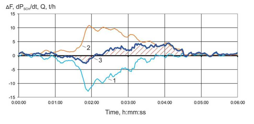
Fig. 4. Graphs of transient processes with the increasing pressure in the major steam line by 0.15 MPa (external disturbance):
1 – change of steam flow of the boiler, t/h; 2 – the reduced rate of change of steam pressure in the steam chamber of the boiler, t/h; 3 – change of the reduced signal by “heat” (the sum of the values of graphs 1 and 2), t/h
Рис. 4. Графики переходных процессов при увеличении давления в общем паропроводе на 0,15 МПа (внешнее возмущение):
1 – изменение расхода пара за котлом, т/ч; 2 – приведенная скорость изменения давления пара в паросборной камере котла, т/ч; 3 – изменение приведенного сигнала по «теплоте» (сумма значений графиков 1 и 2), т/ч
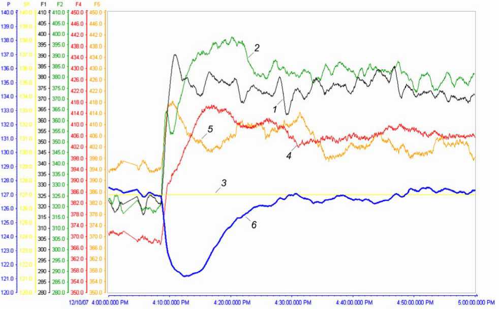
Fig. 5. Graphs of transient processes with increasing electric power output of the Krasnoyarsk TPP-2 by 50 MWt:
1 , 2 , 4 , 5 – steam flow, respectively, of boiler No. 1, 2, 4, 5, t/h; 3 – the set point of the main regulator, bar;
6 – average pressure in the main steam line P М , bar
Рис. 5. Графики переходных процессов при наборе электрической мощности Красноярской ТЭЦ-2 на 50 МВт: 1 , 2 , 4 , 5 – расход пара соответственно котла № 1, 2, 4, 5, т/ч; 3 – задание главному регулятору, кгс/см2;
6 – среднее давление в главном паропроводе P М , кгс/см2
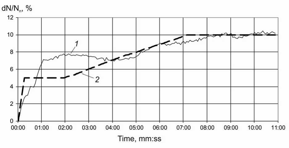
Fig. 6. The graph of the change in the primary power of a TPP when simulating a stepwise decrease in frequency: 1 – station power; 2 – dynamics of primary power output of TPP, according to the technical requirements for generating equipment of the wholesale market participants [1]
Рис. 6. График изменения первичной мощности ТЭС при имитации скачкообразного снижения частоты: 1 – мощность станции; 2 – динамика выдачи первичной мощности ТЭС, согласно техническим требованиям к генерирующему оборудованию участников оптового рынка [1]
In the process of operation of the updated main regulator, the following shortcomings in its work were revealed:
– the dynamics of change of pressure in the major steam line and steam flow outside the boiler, when pressure changes in the major steam line, significantly change when transitioning from winter modes of work to the summer, or when partitioning a major steam line. In these cases, it is necessary to adjust the settings of the regulators, conducting tests with a change in the electrical load of the station and the schedules of electrical power generation;
– the use of the steam pressure signal in the steam chamber of the boiler instead of the steam pressure signal in the boiler drum reduces the influence of external disturbances on the heat load regulator, but also slows down the regulator with internal disturbances and, if necessary, rapid changes in the boiler load;
– since the time constants of the transients on the steam flow rate of the boiler and on the steam pressure in the major steam line are comparable values, the cascades of PI-regulators of MR-HLC have oscillatory properties, which slows down the process of regulating the steam pressure in the major steam line.
Possible solution. Parametric control systems at objects that change their dynamic properties during operation require constant reconfiguration, which significantly complicates their operation.
The procedure of setting up control systems includes several stages:
– annulation of the executive authorities’ characteristics;
– annulation of transient characteristics of the object;
– preliminary determination of the setting coefficients of the ACS;
– experimental setup of ACS at the object;
– testing of ACS.
Characteristics of the executive authorities, as a rule, are annulled once at starting the operation, or after capital repairs. Changes in the characteristics of the executive authorities in the overhaul interval can occur because of wear and tear of the equipment or its failure, which can significantly affect the quality of the parametric control system.
The transient response of the object allows determining its dynamic properties for the calculation of the setting coefficients of the ACS.
The transient response is removed when applying a single disturbing influence. The main parameters for determining the setting coefficients of the ACS are the dynamic characteristics of the object, such as the gain, the transition time constant and the delay time.
Methods for determining the setting coefficients of the ACS can be divided into accurate and approximate, search and non-search, working in real time or not. A list of some methods for determining the setting coefficients of the ACS is below: E. G. Dudnikov's method [4], V. Ya. Rotach's method [5], V. R. Sabanin and N. I. Smirnov’s method [6], method of determining settings by nomograms [7], scaling method [8], Ziegler-Nichols method [9], adaptive method for oscillation by Rotach V. Y. [10], adaptive method using the transient characteristic of V. Ya. Rotach system [11], method based on the technology of reconfiguration of closed systems [12], VTI method [13], direct adaptive control method [14].
Preliminary determination of the setting factors requires further tests of the ACS at the object with their possible adjustments. This stage causes difficulties in the organization of the experiments, since it is not clear how optimal the values of the setting coefficients of the ACS were in their preliminary determination and how many experiments are necessary for the final configuration of the system. This stage can be optimized using model studies of the system, but this requires an accurate model of the object, reflecting its real technological limitations and the state of the executive authorities.
It is a very complicated task to construct the traditional control systems based on the PI-regulators, using an extended number of parameters that affect the change in steam pressure in the major steam line.
To avoid these disadvantages of traditional automatic control systems, the improved steam pressure control system in the major steam line can be applied. It is based on the use of adaptive non-parametric control algorithms, which use the statistical data obtained from the object during its operation while forming controlled actions [15–17]. Modern computer technology allows not only to accumulate and store large amounts of information received from the object, but also to calculate the control actions in real time.
An example of a block diagram of an improved main regulator is shown in fig. 7. All the necessary controlled parameters related to the effective pressure maintenance in the major steam line are supplied as input to the intelligent control device (CD). The control device, using adaptive control algorithms, forms control actions on regulators of thermal loading of boilers.
The structure of the improved main regulator can additionally solve the following tasks:
– to identify the type of disturbance in the boiler equipment (internal or external) and make the decision to change the current load of the boiler (the correction of the false work of the heat load controllers under external disturbance);
-
– to form control actions before the pressure change in the major steam pipeline counting the input/output steam balance along the major steam line;
-
– to distribute the load on the boilers in the most optimal way (in terms of efficiency);
-
– to track the changes in the dynamic properties of the object and adjust the value of control actions.
Conclusion. Despite the fact that automatic control systems at modern industrial enterprises are based on microprocessor controllers, their algorithmic solutions are still rigid parametric structures that are not able to work effectively when changing the dynamic characteristics of the object. The use of the latest information technologies and modern hardware in the management of complex multi-connected objects that solve not only the problems of process control, but also the problem of improving the economic and environmental performance of enterprises, should become a new ыеуз in the development of automatic control systems.
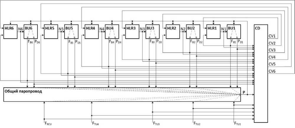
Fig. 7. Block diagram of the improved main regulator:
BU1, BU2, BU3, BU4, BU5, BU6 – boiler units; HLR1, HLR2, HLR3, HLR4, HLR5, HLR6 – boiler heat load regulators;
CD – intelligent control device; N1, N2, N3, N4, N5, N6 – coal feeder speed; F B1 , F B2 , F B3 , F B4 , F B5 , F B6 – steam flow at the boiler outlet; P D1 , P D2 , P D3 , P D4 , P D5 , P D6 – boiler drum pressure; F TU1 , F TU2 , F TU3 , F TU4 – steam flow for turbine units; F RCU – total steam flow for reduction cooling units and other controlled steam outlets; P – main steam line pressure; CV1, CV2, CV3, CV4, CV5, CV6 – control values to boiler’s HLR from the CD
Рис. 7. Структурная схема улучшенного главного регулятора:
КА1, КА2, КА3, КА4, КА5, КА6 – котлоагрегаты; РТН1, РТН2, РТН3, РТН4, РТН5, РТН6 – регуляторы тепловой нагрузки котлов; УУ – интеллектуальное управляющее устройство; N1, N2, N3, N4, N5, N6 – обороты питателей угля; F К1 , F К2 , F К3 , F К4 , F К5 , F К6 – расход пара на выходе из котла; P Б1 , P Б2 , P Б3 , P Б4 , P Б5 , P Б6 – давление в барабане котла; F ТА1 , F ТА2 , F ТА3 , F ТА4 – расход пара на турбоагрегаты; F РОУ,БРОУ – суммарный расход пара на редукционные установки и прочие контролируемые отборы; P – давление в общем паропроводе; УВ1, УВ2, УВ3, УВ4, УВ5, УВ6 – управляющие воздействия на РТН котлов от УУ
References To the task of controlling a group of objects on the basis of information technologies
- Технические требования к генерирующему оборудованию участников оптового рынка от 06 марта 2019. Москва. 193 с.
- Клюев А. С., Лебедев А. Т., Новиков С. И. Наладка систем автоматического регулирования барабанных паровых котлов. М.: Энергоатомиздат, 1985. 280 с.
- Опыт внедрения системы регулирования давления в главной паровой магистрали на Красноярской ТЭЦ-2 / Д. А. Жалнин, В. А. Шорохов, А. Н. Евдокимов [и др.] // Электрические станции. 2009. № 11. С. 18-25.
- Пикина Г. А., Мещерякова Ю. С. Беспоисковый метод расчета настроек ПИД-регуляторов на минимум квадратичного критерия // Теплоэнергетика. 2012. № 10. С. 58-64.
- Ротач В. Я. Теория автоматического управления. М.: Изд. дом МЭИ, 2008. 396 с.
