Trihedral rod pyramid: deformations and natural vibration frequencies

Author: Kirsanov Mikhail Nikolaevich
Journal: Строительство уникальных зданий и сооружений @unistroy
Article in issue: 6 (104), 2022.
Free access
The object of research is a new truss scheme of a statically determinate dome structure. The purpose of the study is to derive formulas for the dependences of the deflection under the action of a uniform load and the first frequency of natural vibrations on the number of panels, sizes, and masses concentrated in the truss nodes. Method. The forces in the truss rods are found from the equilibrium equations of the nodes. The system of equations also includes the reactions of vertical supports located along the contour of the structure. It is shown that the distribution of forces over the structure rods does not depend on the number of panels. The deflection values and stiffness of the truss structure are calculated using the Maxwell - Mohr formula. The lower analytical estimate of the first frequency is obtained by the Dunkerley method, the upper one by the Rayleigh energy method. As a form of truss deflection in the Rayleigh method, the deflection from the action of a uniformly distributed load is taken. Only vertical oscillations of the weights are assumed. Results. The dependence of the solution on the number of panels is obtained by generalizing a series of solutions for trusses with a successively increasing number of panels. The solution uses operators of the Maple computer mathematics system. Graphs of the dependence of the deflection on the number of panels for different truss heights are plotted. The horizontal asymptote of the solution of the deflection problem is found. The value for the first natural frequency is compared with the numerical solution obtained from the analysis of the entire spectrum of natural frequencies of the vertical oscillations of the mass system located in the truss nodes. The frequency equation is compiled and solved using the eigenvalue search operators in the Maple system. It is shown that the lower analytical estimate based on the calculation of partial frequencies differs from the numerical solution by no more than 37%, while the upper estimate has an error of 7%. In this case, the formula for the lower Dunkerley frequency estimate turns out to be more compact. The natural frequency spectrum of the truss is analyzed. Isolines were found in the set of frequencies for a series of regular trusses.
Spatial truss, dunkerley method, maple, induction, frequency spectrum isoline, rayleigh formula
Short address: https://sciup.org/143179859
IDR: 143179859 | UDC: 69 | DOI: 10.4123/CUBS.104.1
Text of the scientific article Trihedral rod pyramid: deformations and natural vibration frequencies
Schemes of spatial regular statically determinate trusses are quite rare [1], [2], Calculation methods using symbolic mathematics, for example, Maple, which has special operators for solving systems of linear equations in the symbolic form [3], apply to such constructions. If the goal is to obtain an analytical solution in the form of a closed formula, then when modeling structures, it is necessary to make several simplifications. As a rule, the construction is simplified to a statically determinate one. In some cases, the construction, for example, a truss, is statically determinate and completely satisfies the designer. If at the same time it is regular, that is, it contains periodically repeating structural elements, then for such a design it is possible to obtain calculation formulas for an arbitrary number of repeating elements. Regular trusses are planar or spatial trusses with the same panels. The number of panels (construction order) can be very large. In this case, the analytical solution has a great advantage over the numerical one, not only due to saving computation time, but also due to the fact that numerical solutions can accumulate rounding errors. This affects the calculations of large-sized systems. The method of induction is used to obtain calculation formulas for deflection, forces in rods or frequencies of natural oscillations for an arbitrary number of panels. Analytical solutions are especially effective in truss optimization problems [4], [5].
Solutions for deformations of planar trusses with an arbitrary number of panels are obtained inductively and some problems on natural frequencies of regular structures are solved [6]–[8]. The lower limit of the first frequency of natural vibrations of a spatial cantilever beam, depending on the number of panels, was obtained by induction in [9]. Jaya's no-parameter algorithm (PFJA) is used in [10] to optimize the size and layout of planar and three-dimensional trusses, subject to natural frequency constraints.
Great contribution to the development of the theory of calculation and optimization of regular rod systems contributed by A. Kaveh [11], [12]. Article [13] proposes multicriteria problems of structural optimization of trusses with a combination of new contradictory objective functions and constraints, such as natural frequencies and load factors, taking into account the overall stability of the structure. In [14], [15] in analytical form, the deflections of planar arched trusses are calculated by induction. The obtained formulas for the deflection after some transformations can also be used to find the natural frequency of oscillations using the Dunkerley method. It has been noted [16] that the lower bound obtained by the Dunkerley method depends on the number of panels and gives less accuracy than the Rayleigh method. Nonlinear oscillations of a rotating circular spatial truss (antenna) subjected to thermal excitation were studied in [17]. An analytical solution can be a convenient way to test numerical solutions, which most often use the finite element method.
Known works that deal with pyramidal trusses usually use numerical calculation methods [18]. In [19]–[21] the properties of pyramidal trusses are studied in connection with the design of structural panels in which trusses act as reinforcement.
In [22] in numerical and experimental form an impact on a sandwich plate consisting of the simplest pyramids is considered.
Very often, for dynamic analysis, simplified models are used, consisting of rods connected in a bundle at the top in the form of a pyramid, but without any lattice [18].
In [23], nonlinear vibrations of a flat steel roof truss were studied during vibrations caused by a sudden failure of one of the load-bearing elements.
There are no analytical studies of deformations and oscillation frequencies of spatial trusses, leading to simple calculation formulas.
In this paper, a new scheme of a statically determined dome-type spatial truss is proposed and formulas are derived for calculating the deflection of the top of the dome and the boundaries of the first natural frequency for an arbitrary number of panels. The spectrum of natural frequencies is studied numerically. The proposed construction can serve as a basis for complicated statically indeterminate systems of this type.
2 Materials and Methods
2.1 Truss scheme
The truss in the form of a regular pyramid 2(h 1 + h 2) high with a triangular base side na contains n s = 18 n rods, including 3( n -1) vertical support posts h 1 high located along the outer contour of the structure and 3( n - 2) posts 2 h 1 high supporting the upper contour (Fig. 1,2).
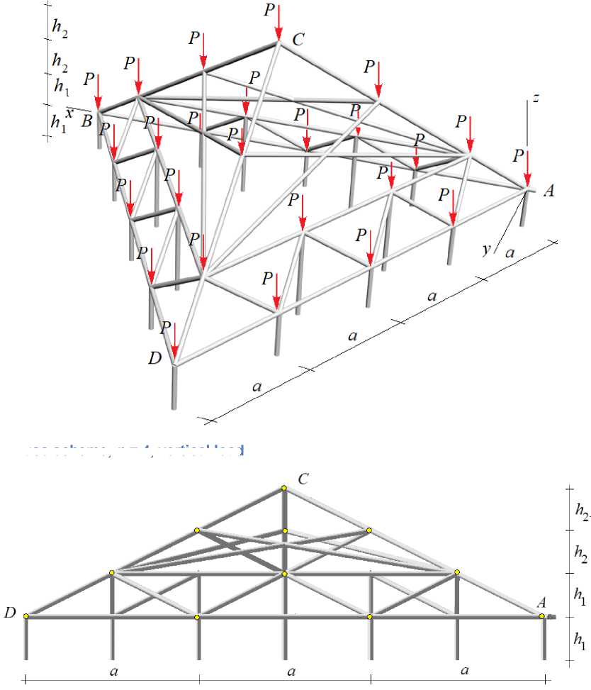
Fig. 2. Truss dimensions, n =3
Fig 1. Truss scheme, n = 4, vertical load
The lower contour consists of 3( n - 2) rods of length a , the upper one consists of 3( n - 1) similar rods. The braces connecting the contours have a length of a2 / 3 + h2 . Corner node A rests on a spherical support hinge, modeled by three mutually perpendicular rods. Node B is a cylindrical hinge corresponding to two support rods, one of which is a vertical post. The following ratios of sizes are chosen: h 1 = h , h 2 = ( n - 1)h / 2. All structure rods are hinged. An analytical calculation of the natural frequencies of a rectangular spatial cover with a similar structure by the Dunkerley method was performed in [24]. The problem of optimizing a spatial truss of 25 rods is solved in [25], [26].
To calculate the forces in the rods, the coordinates of the nodes are entered into a program written in the language of symbolic mathematics Maple [27], taking the origin of coordinates at node A (Fig. 3).
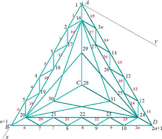
Fig. 3. Numbers of knots and rods of contours
The coordinates of the nodes of the lower contour look like this:
-
x. = a(i — 1), y. = 0, z. = 0,
i , i , xi+n = a(2n — i + 1) / 2, yi+n = a(i — ^V3 / 2, zi+n = 0, x = a(n — i + 1) / 2, y. = a(n — i + 1W3 / 2, z = 0, i = 1,..,n.
i+2 n , i+2 n , i+2 n ,, ,
The coordinates of the nodes of the upper (smaller) contour:
x = a(2i — 1) / 2, y = a(i — 1)V3 / 6, z = h, i+3 n i+3 ni x = a(2n — i) / 2, y = a(3i — 2)V3 /6, z = h, i+4 n—1 i +4 n—1 i+4 n—1
-
x.,t = = a(n — i + 1) / 2, y. „ = a(3n — 3 i + 1W3 / 6, z_ic „ = h , i = 1,.., n — 1.
-
i+5n—2 , i+5n—2 , i+5 n—2 ,, ,
Vertex C coordinate:
x = na /2, y = (y + y„ + y, J/3, z = nh.(3)
6 n—2 6 n—2 v,73 n+1 4 n 5 n—16
The lattice configuration is introduced using special ordered lists of the numbers of the ends of the corresponding rods, by analogy with the assignment of graphs in discrete mathematics. The bars of the lower chord, for example, are encoded by the following lists of vertices
фi = [i,i +1], i = ^..^n — 1,Ф3n = [3n,1].
2.2 Calculation of forces in elements
Upper chord rod coding:
Ф = [i + 3n,i + 3n + 1], i = 1,..,3n — 4,Ф = [3n + 1,6n — 3].(5)
i+3n6
Similarly, other rods are encoded in cycles according to the number of rods.
The system of equations for the equilibrium of nodes in the projection on the coordinate axes has a matrix form GS = T , where G is the matrix of coefficients (directing cosines of the forces calculated from the coordinates of the nodes), S is the vector of unknown forces and reactions of the supports, T is the vector of loads on the nodes. In the elements of the load vector of the form Ф3 i — 2 , where i is the number of the node, the loads on node i in the projection onto the x -axis are written. Elements Ф3 i — 1 contain projections of external forces on the y -axis. Vertical loads are recorded in elements Ф3 i .
Based on the data on the coordinates of the nodes and the structure of the connection of the rods, the projections of unit force vectors in the equilibrium equations of the nodes in the projection on the coordinate axes are calculated
7 - = ( x 7 — x 7 ) / l -, 7 - = ( y r. — y„, ) / l -, 7 - = (z„, — z„, ) / l -, i = 1,..., n + 3,
' x , i Ф , Ф i , 1 y , i Ф Ф i , 1 z , i Ф , Ф i , , , s , ( )
, i ,1 i ,2 , i ,1 i ,2 , i ,1 i ,2
here l = /( x Ф - x Ф )2 + (y Ф - y Ф )2 + (z Ф - z Ф )2 is the length of the rod i . The number of rods also i ,1 i ,2 i ,1 i ,2 i ,1 i ,2
includes three horizontal support rods at corners A and B . The matrix of coefficients of equilibrium equations in projections is filled in rows. Every three lines correspond to the projection equations on the x , y, and z axes, respectively:
G = ч .G . G =.
3Ф ,-2, i ' x , i ’ 3Ф ,-1, i ' y , i , 3Ф ., i ' z , i ,
-
i,1 , , i ,1 , , i ,1 ,,
^ 3Ф ,-2, i 'x , i ’ ^ 3Ф ,-1, i ' y , i ’ ^ 3Ф ,, i ' z , i •
-
i,2 i ,2
Tensioned bars are highlighted in red, compressed bars are highlighted in blue. The thickness of the segments is conditionally proportional to the force modules in the corresponding rods. The force value is given with the sign, referred to the P value, and rounded to two significant digits.
The lower chord is stretched, the upper chord and side ribs are compressed. The braces connecting the chords are not stressed under such a load. The truss has an interesting feature. The forces in the rods from a uniform load do not depend on the number of panels. The compressive forces in the rods of the upper contour for any n are equal to - aP / (6 h ) . The greatest tensile forces are observed in the lower chord: 7 aP / (9 h ) . The most compressed are the lower corner ribs
S = S = S =-- PPc / (9 h ), (8)
6 n -2 7 n -2 8 n -2
where c = V 3 a 2 + 9h 2 .
The forces in the support posts A, B, C do not depend on the dimensions of the structure:
S„ , = S„ , = S, =-10 P / 3. The reactions of the supports of the intermediate posts along the
12 n + 4 13 n + 4 14 n + 4
outer (lower) and inner (upper) contours are equal to P .
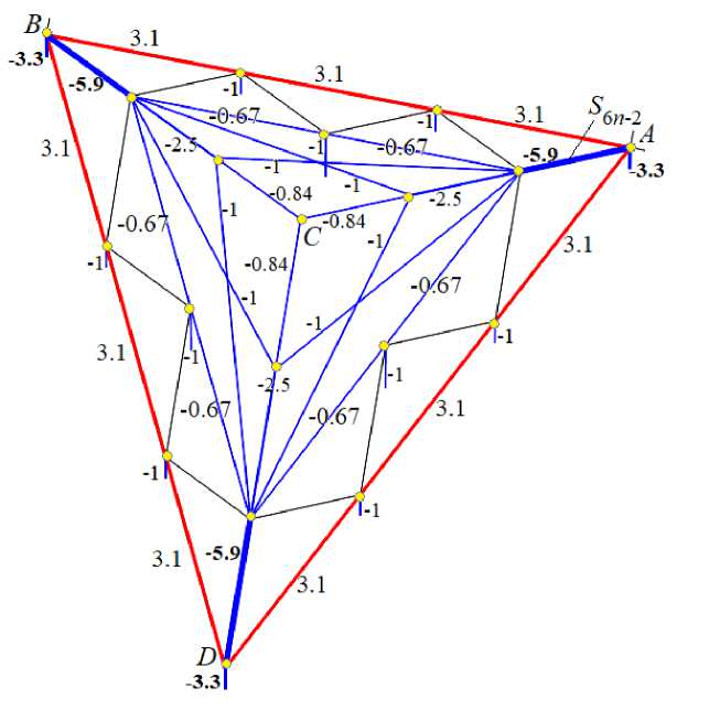
Fig. 4. Distribution of forces in the rods
2.3 Deflection
We derive the formula for the dependence of the deflection of the top C on the dimensions of the structure, the load, and the number of panels. Deflection An refers to the vertical displacement of node C. The Maxwell – Mohr formula hase the form ns Ssl
A = P\—, n EF where Sj is the force in the j-th rod from the action of the load, sj is the force in the rod from the action of a single vertical force applied to the vertex C, lj is the length of the rod, E is the modulus of elasticity of the rods, F is the cross-sectional area. The summation is carried out over all the bars of the structure. It is assumed that the elastic moduli and cross-sectional areas of all rods are the same. The calculation of the deflection of a series of trusses with a successively increasing number of panels gives the following results
A 2 = P(14a 3 + 3 c 3 + 90h 3) / (27 h 2 EF ),
A 3 = P (63 a 3 + 11 c 3 + 270 h 3)/(81 h 2 EF ),
A 4 = P (84 a 3 + 13 c 3 + 270 h 3) / (81h 2 EF ), (10)
A 5 = 5 P (7 a 3 + c 3 + 18 h 3) / (27 h 2 EF ),
A6 = P (126 a 3 + 17 c 3 + 270 h 3) / (81h 2 EF ),...
In the general case, the deflection formula has the form:
A n = P ( c 1 a 3 + C 2 c 3 + C 3 h 3 ) / ( h 2 EF ) . (11)
The coefficients in this expression are functions of the number of panels n . The common members of the sequences they form can be found using the special operators rsolve and rgf_findrecur from the Maple system. Equally effective in finding common members of sequences are the operators of the Mathematica computer mathematics system. The common terms of the sequences of coefficients at n = 2,3,...,7 give the following result
C 1 = 7 n /27, C 2 = (2 n + 5)/81, C 3 = 10/3. (12)
Although the construction under consideration is spatial, the solution for it is much more compact than even for planar trusses [28]. This can be explained by the peculiarity of the stress state of the structure, which does not depend on the number of panels. The same simple solution is obtained in the problem of deflection under the action of one vertical force on vertex C . The coefficients in (11) for such a load have the form
C 1 = n /27, C 2 = n /81, C 3 = 1/3. (13)
Deflection due to the combined action of concentrated and distributed loads can be calculated by a linear combination of solution (11) with coefficients (12) and (13).
Let's build graphs of solution (11), (12) for a distributed load. The total load is fixed
P = P (6 n +1) and the length of the coating side L = na . The dimensionless deflection is denoted as sum
A' = A EF / (P L). In this formulation, the dimensionless deflection decreases with an increase in n sum the number of panels (Fig. 5). The horizontal asymptote of the solution (ultimate deflection) is traced. Using the analytical form of the solution and the operators of the Maple system, the lower limit of the relative deflection is obtained: lim A' = h / (9L).
n -^TO
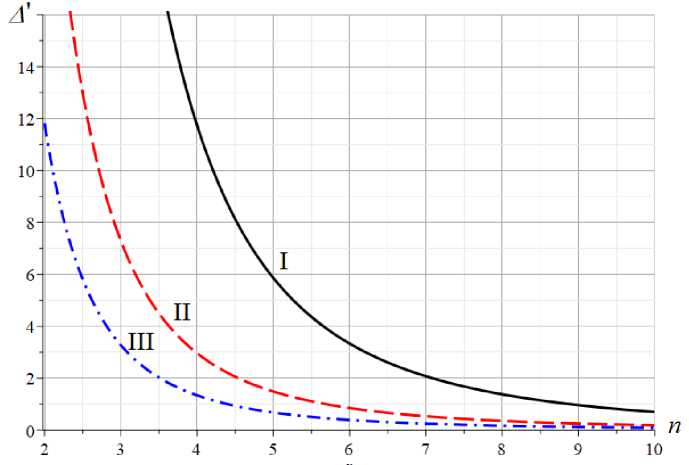
Fig. 5. Dependence of the dimensionless deflection on the number of panels L =50 m; I — h = 0.5m ;
II — h = 1.0 m; III — h = 1.5 m
Solution (11) is easily generalized to the case of different stiffnesses of inclined, vertical, and horizontal truss rods. Taking EF for the stiffness of the chord bars of length a, and EF / 7c for the stiffness of inclined braces and ribs, EF / 7h for the stiffness of vertical support posts, a more general solution with the same coefficients is obtained:
A
n
P (C i a 3 + C 2 C 3 + 7 hC з h 3) h 2 EF
If in the design the rigidity of the belt rods is greater than the rigidity of the other rods, including the supporting ones, то 7 c > 1, 7 h > 1.
2.4 Top displacement due to wind load
Pyramidal structures, having a large windage, are exposed to wind loads. In the case under consideration, such a load can be modeled to some extent by a uniform nodal load along one face of the pyramid (Fig. 6). Nonzero elements of the right side of the equilibrium equation have the form:
^ 3 i - 1 = 1, i = 1,.., n + 1, i = 3 n - 2,..,4 n - 4, i = 6 n - 2,..,6 n.
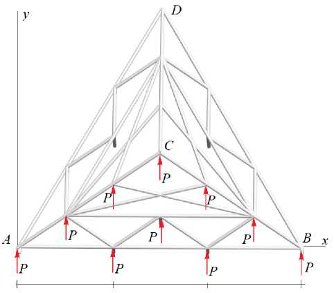
Fig. 6. Wind load y-axis
The dependence of the horizontal displacement 5 n of the peak C in the direction of the wind is being sought. From the analysis of expressions for the deflection of trusses with n =5, 6,.. follows the general form of the solution, similar to (11 ) 5 n = P ( C 1 a 3 + C 2 c 3 + C 3 h 3 ) / ( a 2 EF ) , where the coefficients have the form
C 1 = (5 n 3 - 57 n + 285)/18,
C 2 = (37 n 2 - 79 n + 132)/(162 n ),
C 3 = (4 n 2 - 11 n + 22)/ n .
A distinctive feature of this solution is that it is valid for n greater than 4. Solutions for n =2 and n =3 do not fit into the pattern found.
2.5 Natural oscillation frequency
The value of the first (lowest) frequency of natural oscillations is one of the most important dynamic characteristics of the structure. For this quantity, methods are known for obtaining their upper and lower bounds, free from compiling and solving high-order frequency equations. These methods are based on the calculation of partial frequencies, the values of which can be found analytically. For regular constructions, it is possible to generalize solutions to an arbitrary number of truss panels by induction [7].
The mass of the truss (Fig. 1, 2) is modeled by loads in nodes (hinges). In the simplest formulation, the masses of loads m are the same, the oscillations of the nodes are only vertical. The number of degrees of freedom of the truss weight system of order n is equal to the number of nodes K = 6 n + 1 .
The system of differential equations of cargo dynamics has a matrix form:
M K Z + D K Z = 0, (15)
where Z is the vector of vertical displacements of masses 1,..., K, D K is the stiffness matrix, M K is the inertia matrix of size K x K , Z is the acceleration vector. In the case of identical masses of loads, the inertia matrix is proportional to the identity matrix M K = m I K . The elements of the compliance matrix B K , which is the inverse of the stiffness matrix D K , can be found using the Maxwell-Mohr formula:
n
s
b , = Vs(iS(jl /(EF), i, j / -v a a a a=1
where S ^i ) is the force in the rod a from the action of a single vertical force at node i. Multiplying (15) from the left by B K , taking into account the replacement Z = - ш 2 Z corresponding to harmonic oscillations
zk = uk sin(шt + V0), the problem reduce to the problem of eigenvalues of the matrix BK: BKZ = AZ, where A = 1 / (mш2) is the eigenvalue of the matrix BK, ш is the eigenfrequency of oscillations. Hence foll,ows ш = ^ 1 / (mA).
The forces S(i) in the truss rods included in the elements of the matrix B are determined from a K the solution of the system of equations of the truss nodes, which also includes the reactions of the supports.
It is not possible to obtain analytical solutions for a truss with an arbitrary number of panels.
Consider approximate methods that give estimates of the first frequency from below and from above.
2.6 Energy method. Top rating
The Rayleigh formula, which follows from the equality of the maximum values of the kinetic and potential energies, has the form:
T max
П max
.
The system consists of K identical masses m located at the nodes of the structure. The kinetic energy of the system has the form:
K
T = £ mv2/2.
i =1
According to (17), the vertical velocity of mass i has the form: v = z . = wu sin( wt + у 0) . From here, taking into account that max(sin( wt + ^ 0)) = 1 corresponds to the maximum kinetic energy, it follows:
K
T = w 2mVu 2 /2, (20)
max / v i i=1
where the amplitude of the vertical displacement is calculated by the Maxwell-Mohr formula: nn ss и = V s(pSil / (EF) pV SpSil / (EF) = pu..
i / a a a ' а а аг a=1
Designations are introduced: S ap ) is the force in the rod a = 1,..., n s from the action of the load P distributed over the nodes, S ai ) is the force in the same rod from a single (dimensionless) load applied to the mass with number i , S ap ) = S*ap ) / P . The choice of such a load is determined by the proximity of the deflection form to the oscillation form cargo systems with the first frequency. Thus, (20) takes the form:
K
T = P 2 w 2 У mu /2, (22)
max / г i=1
where U = u / P = У S pS(il /(EF) is the amplitude of mass displacements with the number i i i 1 / a a a a=1
under the action of a distributed load (Fig. 2), referred to the value P .
The potential energy of deformation of the truss rods under the action of a distributed load has nn ss the form: П = УS(p)Al /2 =У(S(p))2l /(2EF). Due to the linearity of the problem max / a a 1 / x a a a=1 a=1
N
S ( p ) = / A s i ) . Hence, a / -v a i =1
n s KKn s N
П = p2У S(p)y S(il /(2EF) = p2У yS(pSiil /(2EF) = p2Vu_ /2.
max / -J a / -J a a > ' / j / J a a a >i a=1 i=1 i=1 ai
From (11), (18), (22) the upper estimate of the first oscillation frequency of the truss follows (the Rayleigh formula):
KK wR = EUi / 2 mu2.
i=1
To obtain the required dependence of the frequency on the number of panels, the displacements u i must also be obtained as a function of n . The solution plan is as follows: 1) calculation of mass displacement with number 1 for different values of n, followed by determination of the common term of sequences u 1( n ) , 2) similar calculation of mass displacements with numbers 2, 3, 4, ... . 3) generalization of formulas UT(n ), U 2( n ), nnn ),... according to the mass number and obtaining the
KK desired dependence йк(n ) , 4) calculation of the common terms of the sums У Ui and У u 2 . i =1 i =1
The calculation of the displacement for trusses with different numbers of panels shows that the K form of the solution У Ui does not depend on n. The numerator and denominator in (24) are i =1
calculated separately. The numerator has the following form: K
У - i = ( g a a 3 + gc 3 + g d d 3 + g ^ h 3) / (324 h 2 EF ), (25)
i =1
or in a more compact form
ЕЛ = Е mm -3/(324h2EF),(26)
i =1 a =[ a , c , d , h ]
where ga = 3(27 + 102n2 - 17n), gc = 8(13n + 1), gd = n - 1, gh = 54(27n2 + 75n + 56).
The denominator (24 ) has a more complex form:
2М = Е mfa0“3 9 3/(243h4 E2 F2), k=1 a, 9=[ a, c, d, h ]
where fa = (3468n3 - 2033n2 + 1782n - 81) / 96, fc = (7n2 + 203n - 14) / 54, fdd = (n - 1)2 / 2592, fhh = 3(90n3 + 297n2 + 507n + 560), fac = (180 - 241n + 845n2)/36, fad = (25n + 3)(n - 1) / 144, (29)
fah = 3(153n3 + 177n2 + 122n + 108) / 2, fdh = 5(n - 1) / 2, fcd = (n + 6)(n - 1) / 108, fc = 63n2 + 134n + 83.
Thus, the upper estimate of the first frequency of the truss, depending on the number of panels, can be obtained by the formula:
w
R
= h
3EF Е g aa 3
a =[ a , c , d , h ]
4 m Е f a9 a 3 9 3
a , 9 =[ a , c , d , h ]
with coefficients (27), (29) depending only on the construction order n .
2.7 Dunkerley score
The lower estimate of the first oscillation frequency is obtained by the Dunkerley formula:
-2
K
D
= E
i =1
where w i is the oscillation frequency of one mass m located at node i . To calculate partial frequencies w i , equation (15) is written in the scalar form:
mz. + D.z. = 0, i ii
where z i is the vertical displacement of the mass, z i is the acceleration vector, D i is the scalar stiffness coefficient ( i is the number of the mass). The frequency of vibrations of the load w i = ^ D i / m . The stiffness coefficient, inverse to the compliance coefficient, is determined by the Maxwell-Mohr formula, similar to (9):
n^ ,.\2
-
6. = 1/ D i = E ( S 7 ) l a /( EF )■ ( 33 )
a =1
Here it is denoted S ai ) — the forces in the rod with the number a from the action of a single vertical force applied to the node i . Arguing in the same way as when calculating the frequencies of a system with many degrees of freedom, one can obtain
K K K K n s 2
w - = E w - = m Е 77 = m Е 6 , = m EE ( S* ) l . /( EF ) = m " n / ( hEF )■ (34)
i =1 i =1 . i =1 i =1 a =1
Let us successively calculate the sums S n
K n s
= h EE ( s a ') ) i i =1 a =1
for n = 2,3,4,5:
S 2
S 3
S 4
561 g 3 + 105 c 3 + 5805h 3 + 2d3
2214 g 3 + 314 c 3 + 26892 h 3 + 9 d3
5658 g 3+677 c 3+71901 h 3+24 d3
1155 g 3+123 c 3+14958 h 3+5 d3
Computing the common terms of the coefficient sequences in these expressions gives:
S = У r a 3, na a=[ a, c, d, h ]
where rg = (73n2 - 60n + 15) / (108n), rc = (6n3 + 23n2 - 20n + 5) / (162n2), rh = (54n3 - 43n2 - 30n + 15) / (6n2), rd = (n - 1) / 324.
When deriving expressions for coefficients (37), the same operators of the Maple system were used when obtaining solution (11) for the deflection. The only complication here was that in the coefficients (37) not only the numerator but also the denominator changes. Direct application of Maple operators to elements of sequences does not allow one to extract common members of sequences. Success was achieved only after the denominator change functions (linear and quadratic in n) were guessed.
The result is the lower limit of natural fre quency accord ing to Dunkerley:
W D =
EF m У r a3 (38)
/ J a a= [ a, c, d, h ]
The structure of the Dunkerley estimate (38) coincides with formula (30) obtained by the energy method, but formula (38) is much simpler. All coefficients for which the inductive method is required are contained only in the denominator (38).
-
3 Results and Discussion
The error of the obtained estimates can be estimated using an example. Let us consider trusses with n panels with dimensions h = 4m, a = 0.3 m. The mass of loads in nodes depends on the number of panels. The total length of all structure bars is equal to L S = 3 ^ 3 n - 4 j h + ^ 3 n - 2 j c + ^ n - 1 j d + 3 ^ 2 n - 1 j .
The mass per one node is calculated by the formula m = L S Fp / (6n +1) , where L S Fp is the mass of all rods, distributed over the nodes. The stiffness of the steel rods of the truss is EF = 3.2 • 10 8 N , the density of steel p = 7900 kg / m3 . The first natural oscillation frequency w R of the truss (30), obtained by the Rayleigh energy method, and the Dunkerley estimate (38) approach the minimum value of the frequency spectrum with a small number of panels (Fig. 7).
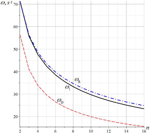
Fig. 7. The first oscillation frequency obtained in three ways depending on the number of panels
The numerical value of the natural frequency of a system with K = 6 n + 1 degrees of freedom found as the minimum frequency of the full frequency spectrum, is very close to the Rayleigh estimate. To refine the estimate of the degree of obtained approximations, it is necessary to introduce the value of the relative error
E D =| ^ D - ^Ш 1 , ^ R =1 W R - - ' / ШГ (39)
Depending on the number of panels, the error of the Dunkerley soluti o n varies from 21% to 34% for a large number of panels (Fig. 8). It is also noted that the degree of approximation of the Dunkerley and Rayleigh estimates is almost independent of the size of the truss.
With an increase in the number of panels, the errors of analytical estimates increase, but at a decreasing rate Rayleigh's estimation error is approximately 7%, and Dunkerley's is 34%.
Higher vibration frequencies are usually not used in engineering calculations, except, perhaps, for studies of resonance cases. The natural oscillation frequency caused by the operation of various devices (machine tools, fans, etc.) can coincide with the natural oscillation frequency of the structure. It is not possible to calculate these frequencies analytically, but the debugged mathematical apparatus in the mode of numerical calculations gives an interesting picture of the sets of spectra of regular systems. In figure 8, ten conditional curves connect the points corresponding to the oscillation frequencies of trusses of orders n = 2,..,10. Each curve corresponds to a truss of a given order, the ordinates of the points on it are the frequencies. The abscissa shows the numbers of natural frequencies in the ordered spectra. The spectrum of the simplest truss at n =2 contains K = 6 n + 1 = 13 frequencies, the spectrum of a truss of order n = 11 consists of 67 frequencies.
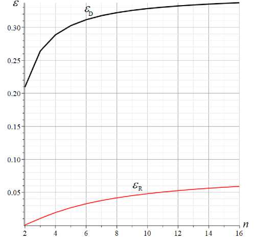
Fig. 8. Dunkerley's and Rayleigh estimation error depending on the number of panels
Some features of the frequency distribution are noticed here. First, all spectra are characterized by sharp, very significant frequency jumps. Regardless of the truss order, the first seven frequencies range from 10 to 350 Hz. The following frequencies also form a certain group (sound frequencies from 2000-2300 Hz). Secondly, many multiple frequencies are found in the system. All higher frequencies for any truss order are multiples. At the same time, regularity can be traced in frequency multiplicity. With n = 2 , the multiplicity of the highest frequency is six (the upper horizontal step on figure 9), with n = 3 already nine frequencies coinciding, with n = 4 there are twelve such frequencies.
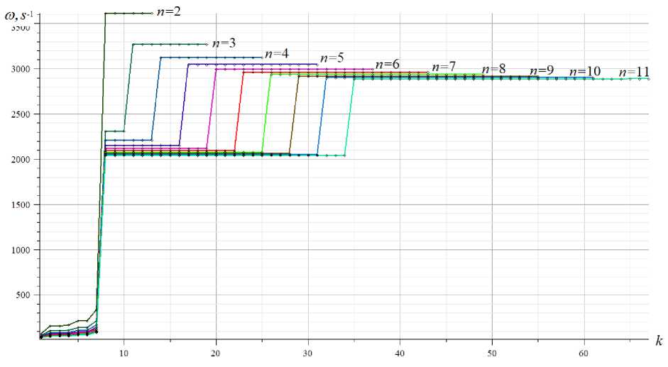
Fig. 9. Frequency spectrum, h = 0.3 m
Continuing further, it can be found that the multiplicity of the highest frequency of the truss of order n is generally equal to 3 n . The same pattern is observed with multiple frequencies in the middle of the spectra. For n = 3, three frequencies are multiples, for n = 4 there are already six of them, and so on. In this group, the general formula for the number of multiple frequencies is different: 3( n -1) . However, there is no exact frequency match here. The frequencies in these groups coincide with very high accuracy and are conditionally called multiples.
In addition, the observed regularity is not universal but is characteristic only for certain values of the truss size. The frequency distribution pattern in the spectra of a group of regular trusses is Kirsanov, M.
Trihedral Rod Pyramid: Deformations and Natural Vibration Frequencies;
especially strongly influenced by the size ratio a / h . The frequency distribution in the spectra of ten of the same trusses, at h = 2.0 m, is shown in figure 10. Here, several groups of multiple frequencies can also be distinguished, with the same regularity for their numbers, as in the previous example.
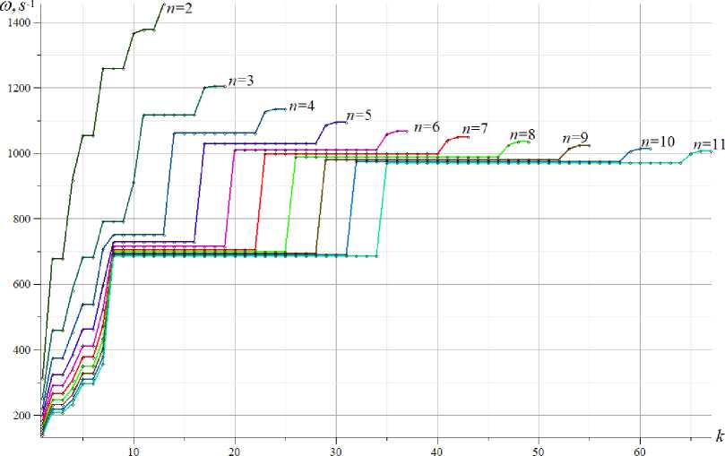
Fig. 10. Frequency spectrum, h =2.0 m
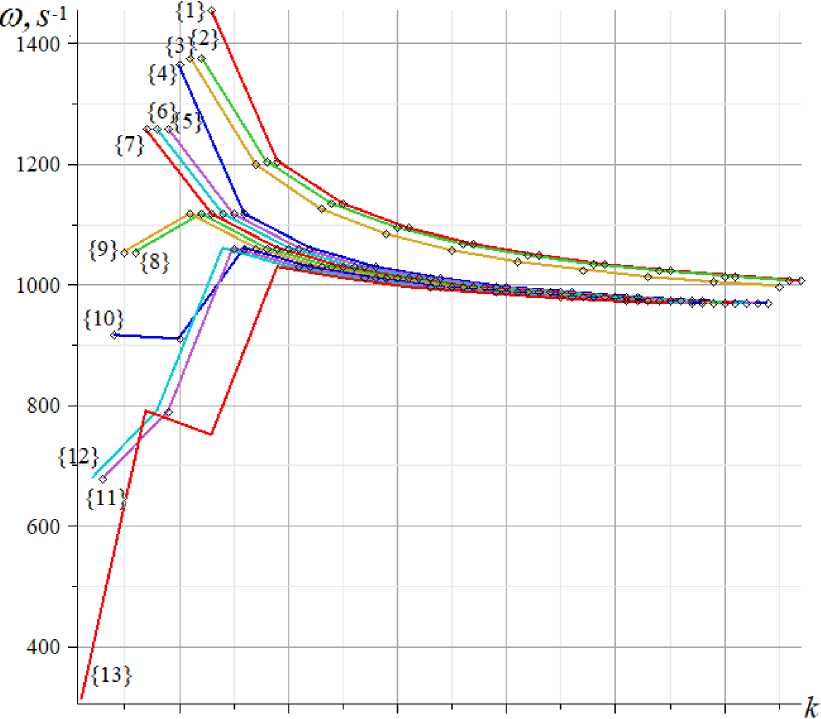
Characteristic repeating groups of three higher frequencies appear on the graphs (except for the case of n = 2), however, in general, the frequency pattern looks almost chaotic. However, one can notice another important feature of the frequency distribution in the spectra. Let us introduce the concept of frequency index — the frequency number in the ordered frequency spectrum of a truss of order n , starting from its end. The frequency index in the spectrum will be denoted by a number in curly brackets.
Thus, there is a relationship between the usual frequency number i , the index { j } and the number of degrees of freedom K : w = w K +1 _ { j }. In particular, the first frequency is the frequency with the index { K }. In the considered truss K = 6 n + 1.
In figure 11, according to the data in figure 10, isolines are plotted — lines connecting frequencies with the same index for trusses of different orders n [29]. The curve with the index {1} passes through the points of higher frequencies of the trusses of order n =2,3,.. 11. The curve {13} consists of the points of the index {13}. For a truss of order n = 2, this is the lowest frequency or the frequency with the highest index in the spectrum. The isolines are ordered into families of curves smoothly converging to some constant frequency, independent of the construction order. Knowing the patterns of frequency distribution in the spectra and their limiting values makes it possible to predict the values of higher frequencies without laborious calculations, which are typical for systems with a large number of degrees of freedom. In this problem, the region of high-frequency concentration is very narrow and is located in the range from 950 to 1050 s - 1 , regardless of the order of the truss.
10 20 30 40 50 60
Fig. 11. Isolines of the frequency spectra, h = 2.0 m
Revealing regularities in the distribution of frequencies in the spectra of regular systems is caused not only by theoretical interest. For practical engineers who design structures that are not subject to possible resonance at higher frequencies, it is important to know in which areas the "clumps" of frequencies are located to take the designed structure out of the dangerous area.
A scheme of a statically determinate spatial coverage truss is proposed. The truss has the shape of a regular trihedral pyramid with two rows of vertical supports - racks along the contour of the lower edge. This design can be used in covering public buildings and structures, such as circuses, arenas, station buildings, and airports.
The truss is externally statically indeterminate. Support reactions can be found only by solving a joint system of equilibrium equations for all nodes simultaneously with the forces in the rods. However, there is a more difficult task here. It is necessary to find the analytical dependence of the deflection of the top of the dome and the first natural frequency on the dimensions of the truss and the number of panels. If the model of a truss or construction with a given number of panels is easy to calculate numerically and even analytically [30]–[32], then for a truss with an indefinite (arbitrary) number of panels, calculation formulas can only be derived by induction on the solutions of several trusses with a successively increasing number of panels. This was done for the considered truss. The formula for deflection as a function of the number of panels turned out to be very simple, due to the property of the truss itself. The calculation showed that the pattern of force distribution over the structure rods does not depend on the number of panels. For example, the number of rods in some belts changes, but the forces in them, as well as the reactions of the supports, remain the same.
If it is quite simple to solve the problem of deflection in symbolic form, then in the general case the problem of frequencies of natural vibrations always reduces to solving the frequency equation — an algebraic equation of order proportional to the number of degrees of freedom. In this problem, the number of degrees of freedom is equal to the number of nodes in which the masses are located, simulating the inertial properties of the structure. It is impossible to obtain an analytical solution to the problem of natural frequencies not only for an arbitrary number of panels but also for a truss with two Kirsanov, M.
Trihedral Rod Pyramid: Deformations and Natural Vibration Frequencies;
panels on the sides. For n = 2, the system already has 13 degrees of freedom. However, sufficiently accurate lower and upper estimates of the first (lowest) natural frequency can be found using the Dunkerley and Rayleigh formulas. Comparison with the numerical solution of the complete problem of the oscillation of a mass system with many degrees of freedom confirmed the well – known fact that the Rayleigh formula for the upper estimate gives much greater accuracy than the Dunkerley method for the lower estimate of the first frequency. The pattern of frequency distribution in the spectra of regular trusses is also shown. The numerical methods of the Maple system were used to calculate the frequencies. An interesting distribution pattern of multiple frequencies and the presence of ordered frequency isolines in the spectra of a family of regular structures have been discovered.
-
4 Conclusions
The main purpose of the work is to develop a project for a spatial regular dome-type structure in the form of a trihedral pyramid. Some requirements were put forward for the design. Firstly, the dome should not rest on central supports, and secondly, the shape of the structure should be regular, which allows the use of inductive methods to derive calculation formulas, taking into account an arbitrary number of panels. In addition, the design must have an architecturally attractive appearance. All these requirements have been met.
Formulas are derived both for deflections and the boundaries of the first frequency. The formulas are practical. They can be used with a very large number of panels, that is, precisely in those cases where the accumulation of calculation errors in numerical form is most likely.
Previously unknown ordered isolines were found in the spectrum of natural frequencies, revealing the region of higher frequency concentration on the plane of the spectra of a series of regular trusses. For the first time, the concept of the natural frequency index in the spectrum is introduced. The closed analytical form of the obtained solutions makes it possible to use all the means of mathematical analysis to identify their features and search for combinations of design parameters that are optimal in terms of strength, rigidity or stability.
-
5 Acknowledgements
This work was financially supported by the Russian Science Foundation 22-21-00473.
References Trihedral rod pyramid: deformations and natural vibration frequencies
- Hutchinson, R.G., Fleck, N.A. Microarchitectured cellular solids - The hunt for statically determinate periodic trusses. ZAMM Zeitschrift fur Angewandte Mathematik und Mechanik. 2005. 85(9). Pp. 607–617. DOI:10.1002/zamm.200410208.
- Hutchinson, R.G., Fleck, N.A. The structural performance of the periodic truss. Journal of the Mechanics and Physics of Solids. 2006. 54(4). Pp. 756–782. DOI:10.1016/j.jmps.2005.10.008.
- Zotos, K. Performance comparison of Maple and Mathematica. Applied Mathematics and Computation. 2007. 188(2). Pp. 1426–1429. DOI:10.1016/j.amc.2006.11.008.
- Feng, J., Sun, Y., Xu, Y., Wang, F., Zhang, Q., Cai, J. Robustness analysis and important element evaluation method of truss structures. Buildings. 2021. 11(10). DOI:10.3390/BUILDINGS11100436.
- Spyridis, P., Strauss, A. Robustness Assessment of Redundant Structural Systems Based on Design Provisions and Probabilistic Damage Analyses. Buildings 2020, Vol. 10, Page 213. 2020. 10(12). Pp. 213. DOI:10.3390/BUILDINGS10120213. URL: https://www.mdpi.com/2075-5309/10/12/213/htm (date of application: 5.02.2022).
- Petrenko, V.F. The natural frequency of a two-span truss. AlfaBuild. 2021. (20). Pp. 2001. DOI:10.34910/ALF.20.1.
- Vorobev, O.V. Bilateral Analytical Estimation of the First Frequency of a Plane Truss. Construction of Unique Buildings and Structures. 2020. 92(7). Pp. 9204–9204. DOI:10.18720/CUBS.92.4. URL: https://unistroy.spbstu.ru/article/2020.92.4 (date of application: 27.02.2021).
- Kirsanov, M., Safronov, V. Analytical estimation of the first natural frequency and analysis of a planar regular truss oscillation spectrum. Magazine of Civil Engineering. 2022. 111(3). DOI:10.34910/MCE.111.14.
- Sviridenko, O. V, Komerzan, E. V. The dependence of the natural oscillation frequency of the console truss on the number of panels. Construction of Unique Buildings and Structures. 2022. 101. Pp. 10101. DOI:10.4123/CUBS.101.1.
- Degertekin, S.O., Yalcin Bayar, G., Lamberti, L. Parameter free Jaya algorithm for truss sizing-layout optimization under natural frequency constraints. Computers & Structures. 2021. 245. Pp. 106461. DOI:10.1016/J.COMPSTRUC.2020.106461.
- Kaveh, A., Hosseini, S.M., Zaerreza, A. Size, Layout, and Topology Optimization of Skeletal Structures Using Plasma Generation Optimization. Iranian Journal of Science and Technology, Transactions of Civil Engineering 2020 45:2. 2020. 45(2). Pp. 513–543. DOI:10.1007/S40996-020-00527-1. URL: https://link.springer.com/article/10.1007/s40996-020-00527-1 (date of application: 4.03.2022).
- Kaveh, A. Optimal analysis of structures by concepts of symmetry and regularity. Optimal Analysis of Structures by Concepts of Symmetry and Regularity. 2013. 9783709115. Pp. 1–463. DOI:10.1007/978-3-7091-1565-7.
- Lemonge, A.C.C., Carvalho, J.P.G., Hallak, P.H., Vargas, D.E.C. Multi-objective truss structural optimization considering natural frequencies of vibration and global stability. Expert Systems with Applications. 2021. 165. Pp. 113777. DOI:10.1016/J.ESWA.2020.113777.
- Rakhmatulina, A.R., Smirnova, A.A. The dependence of the deflection of the arched truss loaded on the upper belt, on the number of panels. Science Almanace. 2017. 28(2–3). Pp. 268–271. DOI:10.17117/na.2017.02.03.268. URL: http://ucom.ru/doc/na.2017.02.03.268.pdf (date of application: 9.05.2021).
- Kazmiruk, I.Y. On the arch truss deformation under the action of lateral load. Science Almanac. 2016. 17(3–3). Pp. 75–78. DOI:10.17117/na.2016.03.03.075. URL: http://ucom.ru/doc/na.2016.03.03.075.pdf (date of application: 9.05.2021).
- Kirsanov, M., Maslov, A. Estimation of the Natural Vibration Frequency of a Triangular Mast. AlfaBuild. 2021. 17(1704). DOI:10.34910/ALF.17.4.
- Chen, J., Zhang, W., Zhang, Y.F. Equivalent continuum model and nonlinear breathing vibrations of rotating circular truss antenna subjected to thermal excitation. Thin-Walled Structures. 2020. 157. Pp. 107127. DOI:10.1016/J.TWS.2020.107127.
- Santana, M.V.B., Gonçalves, P.B., Silveira, R.A.M. Closed-form solutions for the symmetric nonlinear free oscillations of pyramidal trusses. Physica D: Nonlinear Phenomena. 2021. 417. Pp. 132814. DOI:10.1016/J.PHYSD.2020.132814.
- Li, S., Jiang, W., Zhu, X., Xie, X. Effect of localized defects on mechanical and creep properties for pyramidal lattice truss panel structure by analytical, experimental and finite element methods. Thin-Walled Structures. 2022. 170. Pp. 108531. DOI:10.1016/J.TWS.2021.108531.
- Queheillalt, D.T., Wadley, H.N.G. Pyramidal lattice truss structures with hollow trusses. Materials Science and Engineering A. 2005. 397(1–2). Pp. 132–137. DOI:10.1016/J.MSEA.2005.02.048.
- Wang, Y.Z., Ma, L. Sound insulation performance of membrane-type metamaterials combined with pyramidal truss core sandwich structure. Composite Structures. 2021. 260. Pp. 113257. DOI:10.1016/J.COMPSTRUCT.2020.113257.
- Zhang, G., Wang, B., Ma, L., Xiong, J., Wu, L. Response of sandwich structures with pyramidal truss cores under the compression and impact loading. Composite Structures. 2013. 100. Pp. 451–463. DOI:10.1016/J.COMPSTRUCT.2013.01.012.
- Ufimtsev, E., Voronina, M. Research of Total Mechanical Energy of Steel Roof Truss during Structurally Nonlinear Oscillations. Procedia Engineering. 2016. 150. Pp. 1891–1897. DOI:10.1016/J.PROENG.2016.07.188.
- Kirsanov, M.N. Deformations And Spatial Structure Vibrations Frequency of The Rectangular Contour Type Cover: Analytical Solutions. Construction of Unique Buildings and Structures. 2021. 98(5). Pp. 9805. DOI:10.4123/CUBS.98.5.
- Bekdaş, G., Yucel, M., Nigdeli, S.M. Evaluation of metaheuristic-based methods for optimization of truss structures via various algorithms and lèvy flight modification. Buildings. 2021. 11(2). Pp. 1–25. DOI:10.3390/BUILDINGS11020049.
- Bekdaş, G., Nigdeli, S.M., Yang, X.S. Sizing optimization of truss structures using flower pollination algorithm. Applied Soft Computing. 2015. 37. Pp. 322–331. DOI:10.1016/J.ASOC.2015.08.037.
- Buka-Vaivade, K., Kirsanov, M.N., Serdjuks, D.O. Calculation of deformations of a cantilever-frame planar truss model with an arbitrary number of panels. Vestnik MGSU. 2020. (4). Pp. 510–517. DOI:10.22227/1997-0935.2020.4.510-517.
- Kirsanov, M. Trussed Frames and Arches: Schemes and Formulas. Cambridge Scholars Publishing Lady Stephenson Library. Newcastle upon Tyne, GB, 2020.
- Kirsanov, M., Vorobyev, O. Calculating of a spatial cantilever truss natural vibration frequency with an arbitrary number of panels: analytical solution. Construction of Unique Buildings and Structures. 2021. 94. Pp. 9402. DOI:10.4123/CUBS.94.2.
- Goloskokov, D.P., Matrosov, A. V. Comparison of two analytical approaches to the analysis of grillages. 2015 International Conference on “Stability and Control Processes” in Memory of V.I. Zubov, SCP 2015 - Proceedings. 2015. Pp. 382–385. DOI:10.1109/SCP.2015.7342169.
- Goloskokov, D.P., Matrosov, A. V. Approximate analytical solutions in the analysis of thin elastic plates. AIP Conference Proceedings. 2018. 1959. DOI:10.1063/1.5034687.
- Goloskokov, D.P., Matrosov, A. V. Approximate analytical approach in analyzing an orthotropic rectangular plate with a crack. Materials Physics and Mechanics. 2018. 36(1). Pp. 137–141. DOI:10.18720/MPM.3612018_15.
