Ultrasonic C-Scan Image Processing Using Multilevel Thresholding for Damage Evaluation in Aircraft Vertical Stabilizer

Author: Angelika Wronkowicz, Andrzej Katunin, Krzysztof Dragan
Journal: International Journal of Image, Graphics and Signal Processing(IJIGSP) @ijigsp
Article in issue: 11 vol.7, 2015.
Free access
Following the "on condition maintenance" approach used for extending service life of an aircraft one of the major tasks is a nondestructive testing of its critical elements. Considering that many of elements of operated aircraft are manufactured from polymeric composites a special attention should be paid for diagnosing these elements due to their high vulnerability to barely visible impact damage. One of the primary testing techniques used for inspection of aircraft composite elements is an ultrasonic C-Scan technique which application results in planar images of emitted/received wave attenuation and a time of flight map. Due to the complex nature of barely visible impact damage occurrence it is difficult to analyze resulting C-Scan images. Therefore, using assistance based on image processing may help with "big–data" analysis of collected images. In this paper the authors proposed the image processing algorithm for semi-automatic evaluation of such damage distribution in aircraft composite structures. The algorithm is based on multilevel Otsu thresholding and morphological processing. Using the proposed algorithm an extraction of damage visualization from a C-Scan image as well as its characterization and 3D representation is possible. The developed approach will allow supporting diagnosing of composite structures with impact damage using C-Scan technique.
Ultrasonic testing, C-Scan image processing, damage evaluation, multilevel thresholding, composite structures, barely visible impact damage
Short address: https://sciup.org/15013921
IDR: 15013921
Text of the scientific article Ultrasonic C-Scan Image Processing Using Multilevel Thresholding for Damage Evaluation in Aircraft Vertical Stabilizer
Published Online October 2015 in MECS DOI: 10.5815/ijigsp.2015.11.01
Polymeric composite materials have become ones of the most widely applied in various branches of industry due to their superior strength properties with a simultaneous low mass as well as corrosion resistance. These advantages enable application of such composites in the aircraft industry, where high safety and reliability of structural elements is extremely demanded since it may decide about human lives. For this reason, nondestructive testing (NDT) of aircraft structures is very important both at manufacturing stage (defects can be caused by e.g. improper processes or materials used) as well as during their operation (influence of atmospheric conditions, mechanical and thermal impacts, overloads). The typical damage appearing in such structures can be classified into delamination (separation between layers of a composite), disbonds (lack of adhesive), porosity and foreign object inclusions. Polymer composites are vulnerable to impacts, often caused by bird strikes, hailstorms and stone lofting during starting or landing of an aircraft. Such an impact damage is often called Barely Visible Impact Damage (BVID) since it is often invisible on the surface of a structure. However, even low-velocity impacts are dangerous because they may cause extensive internal damage, such as delamination and a complex net of matrix cracking. These delaminated areas may slowly grow under alternating or fluctuating stress which leads to a loss in stiffness and may result in catastrophic failures. For this reason, a special attention should be paid to early detection and identification of BVID to avoid its propagation. Practiced nowadays damage tolerance philosophy in diagnostics of aircraft structures [1] permits the use of composite structures with certain types and degree of damage. Therefore, regular assessment of the structural integrity of an aircraft is required. On-condition maintenance approach is commonly applied, which relies on the capability of detecting failures before they happen so that preventive maintenance can be initiated.
One of the most common methods used for inspections of composite elements of aircrafts is Ultrasonic Testing (UT). This technique consists in observation of the propagation of ultrasonic waves (high frequency sound energy) in a tested structure. The ultrasonic waves propagate uniformly in homogeneous medium (usually water), whereas when they encounter an inhomogeneity or discontinuity, a portion of sound energy is reflected back from the flaw surface. As a result of application of the most common approach in such tests – the C-Scan ultrasonic imaging, planar images of received (or emitted) wave attenuation and wave time of flight map is obtained. Ultrasonic imaging equipment can be portable and thus use in in-field conditions, which is a significant advantage of this method. Many studies on application of this method have been reported, e.g. in condition assessment of composite structures [2-4], wood poles [5], cement based materials [6], marble sculptures [7], inspections of welding quality [8], corrosion detection [9], etc.
Due to the complex nature of BVID occurrence there are certain problems with proper interpretation of acquired measurement data (C-Scans) obtained using UT. A person analyzing ultrasonic images is needed to have a formal certified experience in this area, namely should be very well acquainted with the internal design of a structure (e.g. geometrical properties of internal architecture of a tested structure, location of bolt connections, embedded elements) and potential damage types and their nature. In order to simplify and automate (at least in a certain degree) damage evaluation procedure the application of image processing techniques to acquired C-Scans is necessary [10]. The first studies on application of image processing in evaluation of ultrasonic images are based on simple techniques such as image segmentation [11] and statistical analysis [12]. Various attempts can be found in the literature that are aimed at using image processing methods for aiding or automating an analysis of ultrasonic scans. Kotropoulos et al. [13] proposed an algorithm based on signal-adaptive filters and self-organizing neural networks for processing of ultrasonic images. Bozzi et al. [14] proposed a procedure of detecting porosity defects in materials used in the aerospace industry employing a 2D wavelet transform and feature extraction process. A method of Momtaz and Sadr [15] concerning detection and clustering of defects in ultrasound images is based on image processing with features extraction using rosette pattern. The approach for C-Scan image processing for evaluation of damage proposed by Rashli et al. [16] was based on extraction and analysis of features specific to analyzed damage sites. An original approach of image segmentation using hybrid algorithm of multilevel thresholding and optimization methods was proposed by Ouadfel and Meshoul [17]. Several studies on automation of damage detection on C-Scan images were based on application of Hough transform [18-20]. The same group of authors has also discovered an application of artificial neural networks for damage evaluation in ultrasonic images [21]. Another approach, aimed at delamination detection in carbon fiber-reinforced plastic (CFRP) panels, is based on fuzzy logic and can be found in the paper of Li et al. [22]. The above-mentioned approaches, however, are usually computationally ineffective (when considering the application of image processing algorithms in on-line mode), and often limited to a small group of tested structures and specific parameters of analysis, thus, the main problem of ultrasonic damage evaluation supported by image processing methods and techniques is a lack of universality of developed algorithms.
Several attempts in damage evaluation in aircraft structures using UT have been done by the Air Force
Institute of Technology (AFIT) specialists. In [23], Dragan et al. proposed an algorithm of detection and identification of damage sites on C-Scan images using edge detection technique. Further studies [24,25] were related to application of detected damage sites for construction of finite element models in order to predict structural behavior and residual life of aircraft composite elements after damage occurrence.
As mentioned before, BVID is a special type of damage which is hardly interpretable basing on C-Scan images due to its complex mechanical and geometrical nature. The aim of this study is to present the developed image processing algorithm that allows for effective evaluation of BVID sites using computationally efficient operations which, in consequence, can be applied for online processing of C-Scan images for supporting NDT of composite aircraft structures.
The paper is organized as follows. In section II an overview of UT methodology and equipment as well as description of the tested aircraft structure is presented. Further, the selected C-Scan images with BVID are shown and discussed, and, based on the problem description, the motivation of performed studies is given. In section III the developed image processing algorithm is introduced, and obtained research results with discussion are presented in section IV. The section V concludes the performed study.
-
II. Testing Methodology and Motivation
-
A. Ultrasonic Inspection of Aircraft Stabilizer
One of recently introduced maintenance approaches for aircraft is the “on condition maintenance” (OCM) approach, which guarantees extension of service life of some airplanes in comparison with the previously applied Hour Service Life approach. One of the major tasks of maintaining airplanes following OCM approach is NDT inspection of their critical elements. Following the analysis of types and frequency of damaging of MiG-29 stabilizers reported in [26] the BVID is one of the most often damage types occurred in critical aircraft elements. The comparative analysis of NDT methods applied for testing of aircraft composite structures (resonance technique, shearography and UT) presented in [27] shows that UT is the most sensitive technique, and therefore it was selected for testing of aircraft structures.
The composite skins of the MiG-29 vertical stabilizer were tested in this study. The skins were manufactured as monolithic ones from CFRP with a thickness range of 1.8-3.2 mm. During assembling the skins are joined to the aluminum substructure with use of bolts and adhesive [27]. The variable thickness of the tested composite skins and presence of holes and stiffening ribs complicate further application of UT considerably.
The NDT tests were performed using MAUS® automated UT scanning system manufactured by Boeing company. This mobile system, among other methods (including eddy current testing, Pitch-Catch, Resonance and Phased Array testing), allows inspection using ultrasonic data capturing basing on selected signal gates. The testing setup of the vertical stabilizer of the MiG-29 aircraft using MAUS® system is presented in Fig.1.
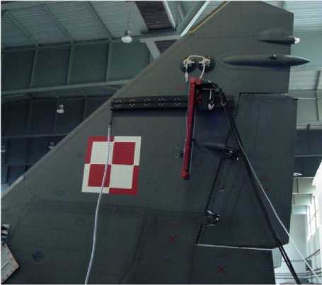
Fig. 1. MiG-29 composite vertical stabilizer during NDT inspection.
The results of UT-based inspection are visualized in the form of C-Scan images that represent a planar map of degree of attenuation or time of flight of emitted/received waves normal to the scanned surface with respect to the planar position of a scanning ultrasonic probe. The degree of attenuation is represented by colors and the sudden local changes of color may indicate sudden changes of a geometry (e.g. stairs-like changes on the thickness), imperfections, foreign inclusions or damage sites. In order to obtain correct results it is important to select appropriate wave generation frequency and consequently the appropriate ultrasonic probe. Considering that CFRP composites are characterized by relatively high damping the 5 MHz transducer was selected for the tests. In order to obtain the best resolution of resulting C-Scan images the highest possible resolution of 0.01” (0.254 mm) per pixel was set up on the device. A Time of Flight (ToF) C-Scan of the complete vertical stabilizer is presented in Fig.2.
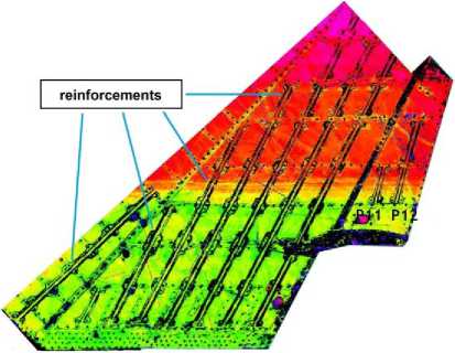
Fig. 2. ToF C-Scan of the tested vertical stabilizer.
The BVID sites are observable in the C-Scan in the form of areas with sudden changes of a color. The color denotes the changes in attenuation, and consequently the damage depth. The monotonic change of a color in the vertical direction is resulted by a change in thickness of the composite skin, while the black regions are the Ω-shaped stiffening ribs (marked in Fig.2 as reinforcements).
-
B. C-Scan Images and Motivation
For the purpose of further analysis three regions with BVID were extracted from the scan presented in Fig.2. The parts of C-Scan considered in further studies are shown in Fig.3. The closer view of the analyzed regions of C-Scan images shows their complex nature, i.e. besides the mentioned color changes the holes for riveted joints are observable.
One can observe that the damaged regions contain many areas colored in different manner which is related to damage existence on various depths. This phenomenon is connected with a specific nature of impact damaging of composite structures, i.e. the damage propagates in such a way that the net of delaminated and cracked areas appears along the thickness direction starting from the impacted surface. Particular damage sites form a characteristic truncated cone due to the distribution of the shear forces.
Considering the physical nature of BVID appearance in composite structures and complexity of resulting coloring of damaged regions an estimation of damage extent and distribution along the thickness direction cannot be performed without application of advanced image processing techniques. The main goal of this study is to separate the damaged regions from ultrasonic C-Scan images and evaluate the damage shape and extent considering distribution of delaminated areas on various depths. Moreover, the developed algorithm should be automated to support NDT inspections of composite structures and further processing of resulting C-Scan images.
-
III. Image Processing Algorithm
The overall scheme of the proposed algorithm, implemented in Matlab®, is presented in Fig.4. The consecutive steps are as follows. Firstly, a C-Scan map is loaded into the workspace as an image (as an example, the second image from Fig.3 is considered). The next operation is the multilevel thresholding with Otsu’s method [28], which consists in quantizing an image using a determined set of threshold values.
The Otsu’s algorithm is a method used for selecting a global threshold value(s) by maximizing separability of clusters in integer-scale images. Let an input image be represented by L gray levels in the range of [0,1,…,L-1]. The number of pixels at level i is denoted by n i and the total number of pixels equals N = n 0 + n 1 + … + n L-1 . For a given gray level image, the occurrence probability of gray level i is given by:
L - 1
pi = i , pi ≥ 0, ∑ pi = 1. (1)
N i = 0
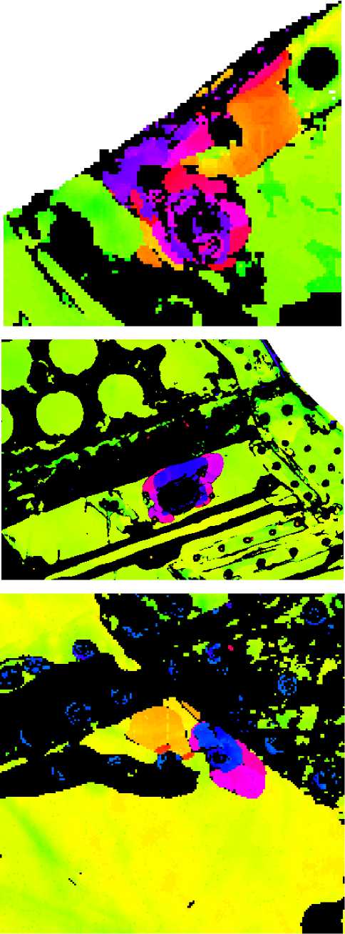
Fig. 3. Parts of ToF C-Scan with detected BVID considered in further analysis.
To segment an image into K predefined clusters (C0, C1, …CK-1) , K-1 thresholds (t0,t1,…,tK-2) need to be defined. The cumulative probability ω k and mean gray level μ k for each cluster C k are given respectively by:
ωk = ∑pi andµk = ∑i⋅ pi/ωk,k∈{0,1,...,K-1}.
i∈Ck
The mean intensity of the whole image μ T and the intra-class variance σ 2 are determined respectively by:
L-1
µT = ∑i ⋅ pi =∑µkωk(3)
i=0
and
K-1
σB2 = ∑ωk(µk -µT)2 =∑ωkµk2 -µT2.( k=0
Following this, the optimal thresholds
0 ≤ t 0 < ... < tK - 2 < L - 1
As an input parameter, 12 levels were assumed which is in relation with C-Scan images scale of wave attenuation. As a result, an image labeled with values of 1-13 is obtained (Fig.5). The subsequent step is the selection of labels, among 12 extracted, representing damage.
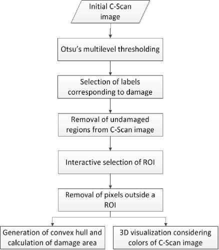
Fig. 4. Scheme of the proposed C-Scan image processing algorithm.
Based on observations on given images it was assumed that in the case of input images with no zero values
(which belong to an empty space in a background in case when a sample is not rectangular) the damage belongs to labels 1-3 and in the opposite case – for input images that contain zeros – labels are offset by one and damage is represented by labels 2-4. This selection of labels is performed automatically by checking the values of an input image. Afterwards, the undamaged regions are removed from the image, i.e. the pixels for which labels are different than the selected ones are assigned to zeros.
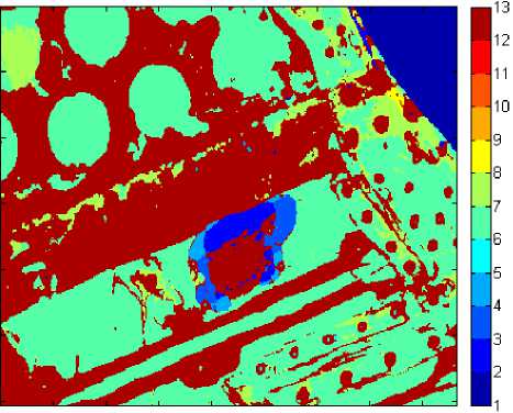
Fig. 5. Image after multilevel thresholding.
The next step is interactive and relies on selecting a region of interest (ROI) by the user (an expert who is able to recognize a damage region) by means of indication of points of a polygon around this region (Fig.6). Then, pixels outside the selected ROI are removed (assigned to zeros) and the positive values inside the ROI are replaced with ones (Fig.7) in order to perform subsequent operations on a binary image. Afterwards, a convex hull of all objects visible in a binary image is generated (in the presented example the objects were taken as one region) and its surface area is calculated using a region properties function. This operation is used in the presented algorithm due to the fact that the interior region of BVID usually represents a damage (massive cluster of cracks or even perforation on the back-side), for which the attenuation is the same as for non-damaged area.
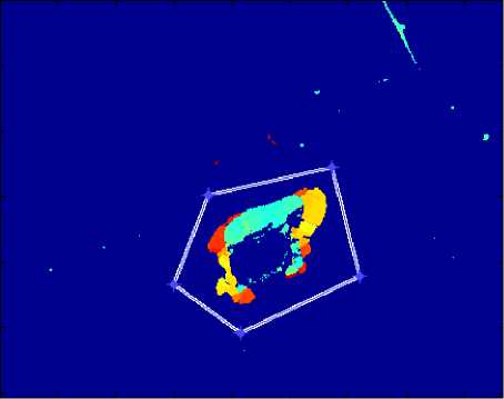
Fig. 6. Interactive selection of a ROI using a polygon.
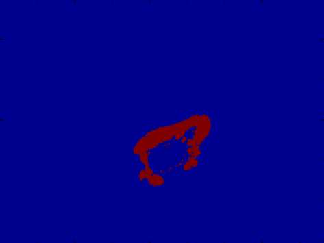
Fig. 7. Extracted region of detected damage.
The convex hull operation guarantees that the whole damage extent is considered during estimation. For the purpose of visual verifying whether the damage was detected properly, boundaries around the detected region are extracted and displayed on the input image. The resulting image is presented in Fig.8.
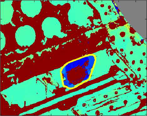
Fig. 8. Extracted boundaries of the region of detected damage.
-
IV. Results and Discussion
The algorithm described in Section III was tested on three available C-Scans and the results are depicted in Fig.8, for the second, and Fig.9, for the first and third image presented in Fig.3, respectively. When comparing the input C-Scans visible in Fig.3 and the results from Fig.9 one can conclude that the proposed method has brought correct results for all considered examples since the extracted boundaries include exactly the damaged regions. The calculated surface area of damage is 27.49 mm2, 60.94 mm2 and 20.55 mm2, respectively for the sequence of the input images presented in Fig.3. These values were obtained for the convex hulls of detected regions in order to obtain information on the overall area of damage that may require repair. Such an approach has one drawback since it may give too mangled results in some cases of shapes of damage sites.
The calculation of only pixels of the detected regions before extracting their convex hulls (e.g. in Fig.7) returned the following surface area: 16.52 mm2, 32.07 mm2 and 15.87 mm2, respectively to the previous results. These results, however, do not give precise information, referring to the real damage, since some undetected pixels inside the extracted regions were not taken into consideration. For this reason, the first approach of calculation seems to be more appropriate for estimating the size of damage.
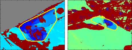
Fig. 9. The results of S-Scans image processing.
sites of different geometrical properties. The obtained results allow concluding about effectiveness of the proposed approach – all analyzed damage sites were detected and evaluated correctly. The detected damage sites were evaluated by determination of damage extent based on planar projections of damage sites. Finally, based on the attenuation levels (different colors on C-Scan images) the 3D graphical representation of damage sites was performed which allows observing the damage extent in particular layers of a composite structure in the thickness direction. The 3D array is reconstructed from planar C-Scans, thus, the damage sites located beyond another ones can be masked which is a disadvantage of this approach. However, among these limitation, the proposed diagnostic approach can be a promising and much cheaper alternative to X-ray computed tomography. Moreover, the achieved preliminary results are planned to be used to other NDT with image data analysis, such as: Eddy Current, Bond Testing, Thermography.
The processed C-Scan images were then transformed to 3D data arrays, where the additional dimension represents colors of damaged regions. Since the color scale is related to the attenuation of emitted/received waves, and thus, the depth of damage location, it was possible to visualize each of considered damage sites considering their locations along the thickness direction. For clarity, the semi-transparent original image (see Fig.3) was merged with the resulting 3D representation of BVID. The 3D visualizations of damage are presented in Fig.10.
The 3D visualizations of BVID allow separating particular delaminated areas caused by an impact and simplify interpretation of C-Scan images. Such an approach enables exact assessment of several delaminated locations, which is necessary for possible structural repair consideration.
The presented approach is the preliminary step of developing a comprehensive algorithm. As it was mentioned before, interpretation of ultrasound images is not easy and requires employing an expert to conclude whether certain regions indicate damage or they result from e.g. an internal design of a structure. Due to the complexity of the considered problem, the presented algorithm need to be further developed.
V. Conclusions
The paper presents the computationally efficient image processing algorithm of damage evaluation of aircraft composite structures based on C-Scan UT technique. Since the complex nature of BVID occurred in such structures and numerous problems of its evaluation and quantization the C-Scan image processing is required. The proposed algorithm is based on multilevel thresholding technique with additional morphological operations which is developed to support diagnostic procedures. The analysis using the algorithm was performed on selected regions of a C-Scan image of the MiG-29 aircraft vertical stabilizer which consists BVID
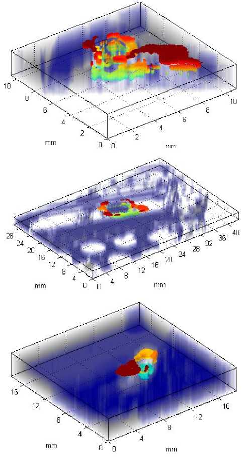
Fig. 10. 3D visualization of detected impact damage sites with backgrounds of tested aircraft structures.
The presented results are the initial part of on-going research. Considering the complex nature of BVID and thus difficulty in interpretation of ultrasonic images the image processing algorithm should be broader elaborated. In further studies the authors plan to develop more sensitive algorithms and their automation as well as hybridization of this diagnostic method with numerical simulations that will allow evaluating residual life of aircraft composite structures.
References Ultrasonic C-Scan Image Processing Using Multilevel Thresholding for Damage Evaluation in Aircraft Vertical Stabilizer
- C.D. Rans, and R.C. Alderliesten, "Damage Tolerance Philosophy for Bonded Aircraft Structures", ICAF 2009, Bridging the Gap between Theory and Operational Practice, pp. 73–90, 2009 [25th Symposium of the International Committee on Aeronautical Fatigue, 2009].
- M.Y. Shiino, M.C.M. Faria, E.C. Botelho, and P.C. de Oliveira, "Assessment of cumulative damage by using ultrasonic C-Scan on carbon fiber/epoxy composites under thermal cycling," Mater. Res., vol. 15, pp. 495–499, 2012.
- A. Katunin, "Stone impact damage identification in composite plates using modal data and quincunx wavelet analysis," Arch. Civ. Mech. Eng., vol. 15, pp. 251–261, 2015.
- A. Katunin, K. Dragan, and M. Dziendzikowski, "Damage identification in aircraft composite structures: A case study using various non-destructive testing techniques," Compos. Struct., vol. 127, pp. 1–9, 2015.
- F. Tallavo, G. Cascante, and M. D. Pandey, "A novel methodology for condition assessment of wood poles usingultrasonic testing," NDT&E Int., vol. 52, pp. 149–156, 2012.
- G. Trtnik and M. Gams, "Recent advances of ultrasonic testing of cement based materials at early ages," Ultrasonics, vol. 54, pp. 66–75, 2014.
- G. Pascale and A. Lolli, "Crack assessment in marble sculptures using ultrasonic measurements: Laboratory tests and application on the statue of David by Michelangelo," J. Cult. Herit., in press.
- ó. Martín, M. Pereda, J.I. Santos, and J.M. Galán, "Assessment of resistance spot welding quality based on ultrasonic testing and tree-based techniques," J. Mater. Process. Tech., vol. 214, pp. 2478–2487, 2014.
- T. Watanabe, H.T.H. Trang, K. Harada, and C. Hashimoto, "Evaluation of corrosion-induced crack and rebar corrosion by ultrasonic testing", Constr. Build. Mater., vol. 67B, pp. 197–201, 2014.
- L. Bechou, Y. Ousten, B. Tregon, F. Marc, Y. Danto, R. Even, and P. Kertesz, "Ultrasonic images interpretation improvement for microassembling technologies characterization," Microelectron. Reliab., vol. 37, pp. 1787–1790, 1997.
- G. Corneloup, J. Moysan, and I.E. Magnin, "Bscan image segmentation by thresholding using coocurrence matrix analysis," Pattern Recogn., vol. 29, pp. 281–296, 1996.
- I. Cornwell, and A. McNab, "Towards automated interpretation of ultrasonic NDT data," NDT&E Int., vol. 32, pp. 101–107, 1999.
- C. Kotropoulos, X. Magnisalis, I. Pitas, and M.G. Strintzis, "Nonlinear ultrasonic image processing based on signal-adaptive filters and self-organizing neural networks," IEEE Trans. Image Process., vol. 3, pp. 65–77, 1994.
- E. Bozzi, G. Cavaccini, M. Chimenti, M. G. Di Bono, and O. Salvetti, "Defect detection in C-scan maps," S. Mach.Perc., vol. 17, pp. 545–553, 2007.
- A. Momtaz and A. Sadr, "Clustering of Ultrasonic C-Scan Images using Rosette Pattern," Int. J. Simul. – Syst. Sci. Tech., vol. 10, pp. 34–39, 2009.
- R. Rashli, E.A. Bakar, and A.R. Othman, "Feature analysis of ultrasonic C-Scan image for nondestructive evaluation," Proc. of the IIEEJ Image Electron. Vis. Comput. Workshop, Kuching, Malaysia, pp. 21–24, 2012.
- S. Ouadfel, and S. Meshoul, "A fully adaptive and hybrid method for image segmentation using multilevel thresholding," Int. J. Image Graph. Signal Process., vol. 5, pp. 46-57, 2013.
- T.M. Meksen, R. Drai, and F. Sellidj, "Pattern recognition in ultrasonic imagery using the Hough transform," Proc. of WCU, Paris, France, pp. 753–756, 2003.
- T.M. Meksen, B. Boudraa, and M. Boudraa, "A method to improve and automate flat defect detection during ultrasonic inspection," Int. J. Adapt. Control Signal Process., vol. 26, pp. 375–383, 2012.
- T.M. Meksen, M. Boudraa, and B. Boudraa, "Automatic detection of circular defects during ultrasonic inspection," Proc. of UKACC Int. Conf. on Control, Cardiff, UK, pp. 1003–1006, 2012.
- T.M. Meksen, M. Boudraa, and B. Boudraa, "Neural networks to select ultrasonic data in non destructive testing," Stud. Comput. Intell., vol. 489, pp. 205–210, 2013.
- S. Li, A. Poudel, and T.P. Chu, "Fuzzy logic based delamination detection in CFRP panels," Informatica, vol. 37, pp. 359–366, 2013.
- K. Dragan, M. Stefaniuk, and P. Synaszko, "Numerical approach for ultrasonic imaging of defects in composites," Compos. Theor. Pract., vol. 12, pp. 105–109, 2012.
- K. Dragan, M. Stefaniuk, A. Czulak, J. Bienia?, M. Dziendzikowski, A. Leski, M. Gude, and W. Hufenbach, "Automated data analysis based on signal processing for two dimensional NDI data of the composite structures," Przetwórstwo Tworzyw, vol. 19, pp. 4–8, 2013.
- M. Stefaniuk, and K. Dragan, "Preliminary approach for an NDT to FEM mapping software used for assessment of delamination-type damage," Proc. of 6th World Conf. Struct. Control Monit., Barcelona, Spain, pp. 2541–2551, 2014.
- K. Dragan, and S. Klimaszewski, "In-service flaw detection and quantification of the MiG-29 composite vertical tail skin," Proc. of European Conference of Non-Destructive Testing, Berlin, 2006.
- K. Dragan, and P. Synaszko, "In-service flaw detection and quantification in the composite structures of aircraft," Fatigue Aircraft Struct., vol. 1, pp. 37–41, 2009.
- N. Otsu, "A threshold selection method from gray-level histograms," IEEE Transactions on Systems, Man, and Cybernetics, vol. 9, pp. 62–66, 1979.
