Underwater sensor networks: an efficient node deployment technique for enhancing coverage and connectivity: END-ECC

Author: Kamal Kumar Gola, Bhumika Gupta
Journal: International Journal of Computer Network and Information Security @ijcnis
Article in issue: 12 vol.10, 2018.
Free access
The deployment of sensor nodes in underwater environment is constrained by some resources of sensor node like: energy, processing speed, cost and memory and also affected by dynamic nature of water. The main purpose of node deployment is to get the sensed data from the underwater environment. One of the major tasks is to cover the whole area in underwater and also there must be a full connectivity in the network so that each sensor nodes are able to send their data to the other sensor node. Some researchers use the concept of node mobility for better coverage and connectivity. This work proposes an efficient node deployment technique for enhancing the coverage and connectivity in underwater sensor network. Simulation results show good performance in terms of area coverage and connectivity.
Underwater sensor networks, sensor nodes, network coverage, connectivity, autonomous underwater vehicles
Short address: https://sciup.org/15015654
IDR: 15015654 | DOI: 10.5815/ijcnis.2018.12.06
Text of the scientific article Underwater sensor networks: an efficient node deployment technique for enhancing coverage and connectivity: END-ECC
Underwater sensor network has gained more interest in the research due to its interesting applications like: environmental monitoring, surveillance, assisted navigation, un-der sea exploration, disaster preventions etc. major equipment’s of underwater sensor network like: sensor nodes, autonomous underwater vehicle, underwater modems and acoustic communication, have play an important role to establish a communication in underwater environment. The major components of underwater sensor node are processing unit, sensing unit, acoustic modem, power unit and communication unit. The sensing unit helps to measure the physical conditions such as pressure and temperature. The processing unit helps to process the data and also convert it in the required signal form. Acoustic modem is used to convert the radio signals into the acoustic signals that help to communicate and power unit provides the required energy to all units to perform their tasks.
There may be hundred or thousand sensor nodes in underwater environment that have ability to communicate with the other sensor nodes. All sensor nodes can also communication directly to the sink node or base station. In current years, underwater sensor network has many applications in the field of environment monitoring, military surveillance, health care, remote sensing etc. [1]. Sensor nodes are used to sense the underwater environment and send the valuable information to the base station. In underwater, sensor nodes use the acoustic signals for communication. The main thing is that all sensor nodes must be able to send the data to the base station that means there must be a full connectivity in the network [2]. The type of deployment reduces overlap problem and improve the network connectivity as well as link quality [3]. For horizontal adjustment, sensor nodes are equipped with floating buoys while for vertical adjustment; sensor nodes are equipped with the floating buoys through wires. These wires are used to control the depth of the sensor nodes. Movement-Assisted Deployment: One or more mobile sensor nodes like: autonomous underwater vehicles (AUVs) or unmanned underwater vehicles (UUVs) are used that assist during deployment and gliders also follow a predefined trajectory for patrolling of a specific region to fulfill some specific monitoring tasks [4].
Following are some major performance parameters that are used to evaluate the performance of the deployment techniques.
Connectivity: it is defined that all sensor nodes must be able to transfer the data to the surface station that means there must be full connectivity in the network which is given by:
Cn= nc/ n (1)
Here n is the number of nodes, n c is the total number of nodes that can communicate to the sink node. If the C n = 1 then all sensor nodes can communicate to the sink node and network achieves full connectivity in the network.
Coverage: it is defined as the ratio of covered area of active sensing to the whole area of Interest which is given by:
Cv = pc / pt (2)
Here p t is total numbers of cube points and p c is covered cube point.
Average Node Degree: it is defined as total number of neighbors of sensor nodes in the network.
Expected Path Length: It is define as number of hops that are available in the path from sensor node to surface station.
-
II. Underwater Sensor Networks Architectures
The architecture of underwater sensor networks is classified into three categories: 1-D, 2-D and 3-D architecture [5]. In 1-D, Sensor nodes are deployed separately and each sensor node is responsible for sensing the data, processing the data and finally transmitting the data packets to the base/remote station. Sensor node may be a floating buoy that can sense the underwater environment. For a particular time period, a sensor node can be deployed in the underwater to sense the information and then again float towards upper to transmit the information to the remote station. Sensor nodes can communicate via nay link like: radio frequency, acoustic or optical communication. In 2-D architecture, sensor nodes fixed at the ocean bottom and communicate with the underwater gateway via acoustic links. The underwater gate-way is responsible to forward the collected data packets/ information to the base station. While in 3-D architecture, multiple autonomous underwater vehicle are used that float at different depth to detect the phenomena. Both architectures consists the several challenges in sensor nodes deployment [6]. Some challenges posed by 2-D architecture are: 1) to determine the minimum number of nodes for communication and target detection, 2) to determine the optimal area for the deployment, 3) to reimburse the link and node failures. Some challenges posed by 3-D architecture that must be resolved are: 1) identify the depth for the node deployment; 2) network cost, 3) connectivity among the nodes to transfer the data packets through multi path.
-
III. Related Works
The design structure of underwater sensor networks has become the most important re-search area for the researchers. One is the node deployment in underwater environment. Many researchers have proposed node deployment techniques for underwater sensor networks. This section shows a detailed survey of node deployment techniques. Table 1. Shows some known deployment techniques with their objective, advantages and disadvantages.
In [7] the authors have proposed a deployment scheme for 3-D architecture having the below components: Sensor node to detect the events, AUV nodes known as autonomous underwater vehicle responsible for collect the data from the sensor node and then relaying that data to the SG (Surface Gateway), lot of SG deployed on the surface of the water to collect the data from the AUV Nodes. A mathematical model is proposed that follow the characteristics of the underwater channel. As this schemes uses the multiple AUV node and SG that overcome the problem of the coverage area of the network and connectivity. A patrolling is done by the AUV node where connectivity is not so strong. It also helps to overcome the problem of interference. In [8] a node deployment algorithm is proposed. This algorithm is based on the connected dominating set (CDS). Sensor nodes are randomly deployed in the three dimension targeted underwater area. Nodes start to move towards the sink node if they are not connected to anyone. This process improves the network connectivity in the network. Sink node finds the CDS and adjust their location. Simulation results show a good performance in terms of network connectivity and coverage rate. In [9] the authors have proposed a routing protocol to cover the maximum area. Here two sink nodes having constant mobility are used for maximum coverage. All sensor nodes send the data packets to the respective sink node when the distance is minimum. These sink node can move clockwise. Simulation results show a good performance as compared to the EBECRP. In [10] a localization based cooperative routing protocol is proposed that maximize the coverage and minimize the localization errors. Here two routing protocols have been proposed. Before the deployment, a GPS system is attached with the autonomous underwater vehicle (AUVs) and these AUVs also act as reference node used to minimize the localization error and maximize the coverage by placing the non-localized sensor nodes. A cooperative mobile autonomous underwater vehicle is also proposed to improve the network throughput. This protocol uses the maximal ratio combining technique to improve the signals. In [11] the author has proposed a self-deployment novel approach in underwater acoustic sensor networks. In this approach, it is assumed that firstly sensor nodes are deployed at water surface. The working of the proposed approach is based on the three phases known as initialization, depth computation and depth distribution to the sensor nodes. In initialization phase, firstly sensor nodes form a tree structure where surface station acts as root and each sensor node sends the location of their respective sub tree sensor nodes to the parent sensor node. In depth computation phase, surface station calculates the depth for each sensor nodes. In last phase, calculated depth is distributed to the sensor node so that each sensor node good performance in terms of area coverage as compared can start the sinking process. Simulation results show a to CDA and CGCA techniques.
Table 1. Comparision of Some Existing Deployment Techniques [12]
|
Ref. No. |
Deployment Type |
Deployment Objectives |
Sensor Types |
Advantages |
Disadvantages |
|
Ref.[13] |
Static Deployment |
To Reduce the overlapping problem |
Underwater sensor node and gateway |
Low energy consumption and low computational complexity |
Complexity is based on the targeted coverage ratio |
|
Ref.[14] |
Static deployment |
To optimize gateway deployment |
Underwater sensor node and gateway |
Redeployment of gateway node, low energy consumption and provide offline service for deployment problem |
High computational complexity |
|
Ref.[15] |
Static Deployment |
To increase the network lifetime |
Cluster head and underwater sensor network |
Multipath data delivery, low energy consumption and reduce the dispute among sensor nodes. |
High computational complexity |
|
Ref.[16] |
Self-Adjusting Deployment |
To Reduce the overlapping problem |
Cluster head and underwater sensor node |
Low computational complexity |
Effect of water current and high energy consumption |
|
Ref.[17] |
Self-Adjusting Deployment |
To maintain the network connectivity |
Underwater sensor node |
Low energy consumption and low computational complexity |
Multihop hierarchical routing |
|
Ref.[18] |
Self-Adjusting Deployment |
To minimize the uncovered area |
Underwater sensor node |
Low energy consumption and maintenance of area coverage |
High energy consumption |
|
Ref.[19] |
Self-Adjusting Deployment |
To maximize the coverage and connectivity |
Dominator node and underwater sensor node |
Guaranteeing connectivity and low computational complexity |
Needs of ultrasonic sensor |
|
Ref.[20] |
Movement-Assisted Deployment |
To maximize the coverage in the network |
Surface gateway and underwater sensor node |
Low computational complexity and prediction of node position |
High energy consumption |
|
Ref.[21] |
Movement-Assisted Deployment |
To drive autonomous underwater vehicle to target |
Autonomous underwater vehicle and underwater sensor node |
Low computational complexity |
High energy consumption |
|
Ref.[22] |
Movement-Assisted Deployment |
To minimize the distance and travel time also |
Autonomous underwater vehicle and underwater sensor node |
Failure detection and recovery, low computational complexity |
High energy consumption |
-
IV. Models
-
A. Node Energy Consumption Model
It is considered that a node consumes low energy for sensing, processing and receiving the information as compared to transmit the information and in moving also [23]. In [24] the same model is used here for transmitting the information.
Ex(d) = P rxTp x A(d) (3)
Where:
E tx ( d ) : Indicates the energy consumption for transmitting the information.
P r : The power threshold of a node that required receiving the information packages.
T p : The transmission time require to transmit the information package. The value of T p is calculated by:
TP = M b / S v (4)
d : Transmission distance
M b : Size of information package
S v : Transmission speed
A ( d ) : Energy attenuation which is calculated by:
A(d=d X x в (5)
Я : Energy spreading factor and the value of X for cylindrical is 1, 1.5 for practical and 2 for spherical spreading and p = 10“(f)/10 is calculated by absorption coefficient “ (f) which is calculated by:
“ f ) = 0.11 ( 10 - 3 f 2 /1 + f 2 ) + 44 ( 10 - 3 f 2 ) /4100 + f 2 ) ^
+ 2.75 x 10 - 7 f 2 + 3 x 10 - 6
Where f is carrier acoustic signal frequency in KHZ and “ ( f ) in dB/m.
Communication energy consumption is defined by:
C = E R\tt (7)
e tx t n
Where t transmitting time for node s, R is communication range for node s and ^ (r ) is communication energy consumption for one information package transmitting.
Movement energy consumption is denoted by:
n
k( Pi) = Z f( PS')
j = 1
Here n is the number of nodes in the network. Function f 0 ( p i ) defines that whether cube point is covered or not.
If f 0 ( p i ) Function value is 1then cube point pi is not covered by any sensor node.
f 0( pi) = {1k( pi) = 0} f 0(Pi) = {1k(Pi) # 0}
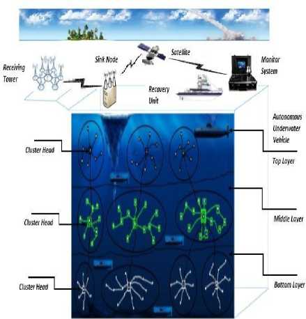
Fig.1. Proposed Model for Underwater Sensor Networks
M = m, xe e d mu
Where m is the movement distance and e is energy d mu consumption per movement distance.
-
B. Node Sensing Model
In [25] the authors have adopted the Boolean sensing model to describe the node sensing.
f (Pi,Si ) = 1 if ( ^( xi - ai )2 +(yi - bi )2 +(zi - ci )2 ) <= R s
f (Pi,si ) = 0 if ( V(xi -ai )2 +(yi -bi )2 +(zi - ci )2 ) > Rs
Here function f (p , s ) defines that whether cube point p can be covered by node s . If the value of this function is 1 that means the cube point is covered by the node and if the value of this function is 0 that means the cube point is not covered by the node.
(x.y .z.) are the coordinates of the node, (a.b.c.) are the coordinates of cube point and s is sensing range.
For the cube point p i , the coverage degree k ( p i ) is defined by given function:
-
V. Proposed Work
-
A. Assumptions
Following are the assumptions that are made during node deployment in underwater sensor network.
-
1- The target region is divided horizontally into three layer like bottom layer, middle layer and top layer.
-
2- All sensor nodes have a same transmission power and equipped with acoustic transceivers.
-
3- Multiple AUVs are deployed at different level of depth and can also be used on behalf of drained node until they are repaired. AUVs are equipped with radio and acoustic transceivers. For underwater communication, AUVs uses acoustic
communication while over water surface AUVs uses radio communication.
-
4- Multiple surface gateways are deployed on water surface and equipped with radio and acoustic transceivers.
-
5- All AUVs maintain their route with the help depth calculation algorithm and location.
-
6- For horizontal adjustment, sensor nodes are equipped with floating buoys.
-
7- For vertical adjustment, sensor nodes are attached to the floating buoys with wires. These wires are used to control the depth of the sensor nodes.
-
B. Network Environment
This work considers a 3-D underwater sensor network architecture where certain numbers of sensor nodes are deployed with equal sensing and transmission range to cover the underwater volume V. The whole network is divided into three layers like: bottom layer, middle layer and top layer. This network environment is having 1) sensor nodes having twofold functionality (sensing and transferring) 2) Multiple Autonomous Underwater Vehicle (AUV) at different depth 3) Multiple Surface Gateway SG on water surface. For underwater communication this work uses acoustic communication while in communication between surface gateway to control center, radio communication is used.
-
C. Description of Proposed Algorithm
Initially all the sensor nodes are deployed at water surface. A tree structure is formed for all the sensor nodes by the surface station. The whole network is divided into layers like: top, middle and bottom layer. The proposed algorithm consists three phase.
Root Selection
-
1- Each sensor node broadcasts a message having Node (id), coordinates(x, y), transmission range, sensing range and energy level.
-
2- Now each sensor node knows these parameters of all other nodes. Here the value of threshold will be defined by surface station. Each sensor node calculates the distance of all other nodes to get the neighbors.
(x2 - x1)2 + (y2 - y1)2 <= T(Range) (12)
Where (x, y) are the coordinates of the sensor node and T_Range is the transmission range.
-
3- Now each sensor node will calculates the total Node_Degree by given formula.
n
ND = ^ Total Numbers of neighbours (13)
k = 0
-
4- Now calculate the total distance for each sensor node by given formula.
n
SV = ^ Total Distance of all neighbours of each node (14)
k = 0
-
5- Calculate the average energy for each sensor node by given formula.
EEAV = 1/SV £ RE (15)
k = 0
Here, RE is the residual energy for sensor node.
RoF = [ ( a * ND ) + ( в * EEAV ) + ( Y * ( 1 / SV ) ) ] (16)
Where α + β + γ =1 α , β and γ are the weighting factors for the corresponding system parameters.
Formation of Tree Structure
After the calculation of root function, sensor node having the highest value of root function will act as root of a tree. A tree request message is broadcast by the root in the network. Only those sensor nodes having one hop neighbours from the root, reply the message and form a connected tree with the root using the concept of binary search tree. If the value of depth function is greater than root then it will place in the right sub tree else place in the left sub tree. Now one hop connected neighbours with the surface station will broadcast a tree request message and again only one hop sensor nodes reply. This process will continue till all the sensor nodes get form a tree structure.
for ( i = 1; i <= n; i + + ) where n is one hop neighbors
{ if (Value of Root Function(Root) <= Value of Sensor Node) {
Add a sensor node in right subtree;
}
Else {
Add sensor node in left subtree;
} }
According to this approach, all sensor nodes have a parent sensor node. Each sensor node computes their depth and sends this information with their ID to their respective parent sensor node.
Calculation of Depth
It is assumed that sensor node having the highest value of root function will be elected as root and always placed at water surface that means for root, the value of z coordinates is set to zero. Suppose if there are three sensor nodes name A, B, C. Sensor node (A) is a root and rest sensor nodes are deployed at water surface. Initially for all the sensor nodes, the value of z coordinate is set to zero. The coordinate for sensor nodes are (A.x, A.y, A.z), (B.x, B.y, B.z) and (C.x, C.y, C.z) respectively.
A.z=0
B.z=0
C.z=0
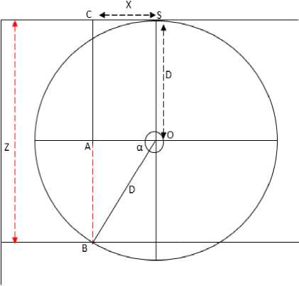
Fig.2. Deployment Based on Signal strength
Where
D is the maximum signal strength.
X is distance at x-axis from sensor node-1 (SN_1)
Z is the total depth from water surface to the sensor node-2 (SN_2).
In above figure CA will be equal to the SO i.e. CA=SO=D and it will also equal to the OB. So the relation is CA=SO=OB=D.
Here we have to find out the distance of AB.
Total depth = Z = f ( d, a )
Z = ( AC + AB )
Sin a = AB/BO = [ ( D2 - ( OA ) 2 ) 1/2 ] /D = [ ( d2 - X2 ) 1'2 ] /D
Z = ( D + [ ( D2 - X2 ) 1/2 ]
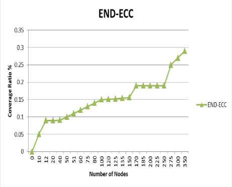
Fig.3. Coverage Ratio vs Number of Nodes
Figure 4, shows the comparision between coverage ratio by varying α=Rt/Rs. The coverage ratio is increase as α increase. It also indicates the scalability of the proposed algorithm being a constant gap (approximate) in the proposed algorithm.
When, X = 0, then Z =
[ ( d + ( D2 )”) ]
= ( D + D ) = 2D
When, X = D, then Z = [ ( d + ( D2 - D2 ) 1/2 ) ] = D + 0 = D
Figure 5, shows the connectivity of the resultant topologies for varying number of nodes. As compared to the existing approach, END-ECC shows good results in terms of connectivity.
For simulation purpose, the depth of water is set to 500m. To evaluate the performance of the proposed scheme, ratio of transmission range and number of sensor nodes vary over the sensing range which is denoted by α=Rt/Rs. In simulation, the transmission range is fixed at 150 m and sensing range at 40 m. hence the ratio α=3.75 and vary the sensor nodes from 50 to 270. The transmission and sensing range of nodes are consistent with the characterstics of the ultrasonic sensors.
Figure 3, shows the comparison between coverage ratios and ratio of transmission range to sensing range for varying number of nodes. According to this figure, the coverage ratio gets decrease as number of node increases while it is expected that it should be increase.
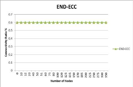
Fig.5. Coverage Ratio vs Number of Nodes
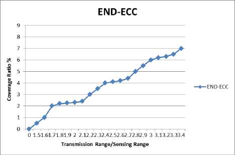
Fig.4. Coverage Ratio vs Transmission Range/Sensing Range
Figure 6, repeated the same experiment for varying α. Again, regardless of α value, proposed approach. Connectivity ratio slightly increases as α increase. END-ECC shows good results in terms of connectivity.
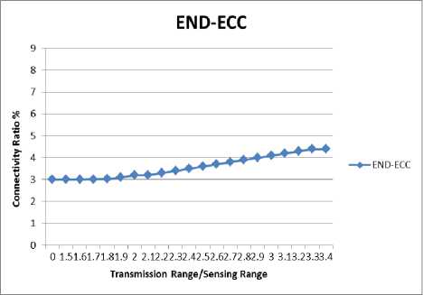
Fig.6. Coverage Ratio vs Transmission Range/Sensing Range
-
VII. Conclusions
In this work, an efficient node deployment technique has been proposed that enhances the coverage and network connectivity in the network. Initially sensor nodes are deployed at water surface. For calculating the depth of all sensor nodes, this work also proposed a depth calculation method. According to the depth, all sensor nodes are deployed at different water level. Simulation results show a better performance in terms of network coverage area and network connectivity rate. The proposed algorithm also de-creases the movement and communication energy consumption during the deployment. For future work, this work can be extend to resolve the problem of coverage overlapping so that a less number of sensor nodes are required to cover the maximum area and also provide the full network connectivity.
-
[6] Cayirci, E.; Tezcan, H.; Dogan, Y.; Coskun, V. Wireless
sensor networks for underwater survelliance systems. Ad Hoc Netw. 2006, 4, 431–446.
-
[7] Manjula R. Bharamagoudra, Sunil Kumar S. Manv,
Deployment scheme for enhancing coverage and connectivity in underwater acoustic sensor networks. Wireless Personal Communications 2016, Vol 89, 12651293.
-
[8] L. Jun, J. Peng, W. Feng, Y. Shanen, S. Chunyue. Node
redeployment algorithm based on stratified connected tree for underwater sensor network. Sensors, 2017, 17, 27.
-
[9] J. Peng, L. Jun, W. Feng, W. Jianzhong, X. Anke. Node
deployment algorithm for underwater sensor networks based on connected dominating set. Sensors, 2016, 16, 388.
Conference, July 28-30, 2015, Hangzhou, China.
-
[11] Z. Arslan, J. Nadeem, A. Mariam, K. Zahoor Ali. A New Routing Protocol for Maximum Coverage in Square Field for Underwater WSNs. IEEE 31st International Conference on Advanced Information Networking and Applications, 2017, Taipei, Taiwan.
-
[12] Tuna G, Cagri Gungor V. A survey on deployment techniques, localization algorithms, and research challenges for underwater acoustic sensor networks. Int J Commun Syst. 2017.
-
[13] J. Nadeem, M. Hammad, W. Abdul, N. Iftikhar Azim, A. Ahmad, A. Atif, and I. Manzoor. A Localization Based Cooperative Routing Protocol for Underwater Wireless Sensor Networks. Mobile Information Systems, Volume 2017, 2017.
-
[14] Senel F. Coverage-aware connectivity-constrained unattended sensor deployment in underwater acoustic sensor networks. Wireless communication and mobile computing, 2016.
-
[15] Pompili D, Melodia T, Akyildiz IF. Three ‐ dimensional and twodimensional deployment analysis for underwater acoustic sensor networks. Ad Hoc Netw. 2009; 7(4):778‐790.
-
[16] Felemban M, Shihada B, Jamshaid K. Optimal node placement in underwater wireless sensor networks, in Proceedings of the Advanced Information Networking and Applications, 2013; 492–499.
-
[17] Han G, Zhang C, Shu L, Rodrigues JCPC. Impacts of deployment strategies on localization performance in underwater acoustic sensor networks. IEEE Trans Ind Electron. 2015; 62(3):1725‐1733.
-
[18] Akkaya K, Newell A. Self‐deployment of sensors for maximized coverage in underwater acoustic sensor networks.Comput Commun. 2009; 32(7 ‐ 10):1233 ‐ 1244.
-
[19] Xia N, Wang C‐S, Zheng R, Jiang J‐G. Fish swarm inspired underwatersensor deployment. Acta Automat Sin. 2012; 38(2):295‐302.
-
[20] Aitsaadi N, Achir N, Boussetta K, Pujolle G. Differentiated underwater sensor network deployment, in Proceedings of the OCEANS —Europe, 2007; 1–6.
-
[21] Senel F, Akkaya K, Erol‐Kantarci M, Yilmaz T. Self ‐ deployment of mobile underwater acoustic sensor networks for maximized coverage and guaranteed
connectivity. Ad Hoc Netw. 2014;
-
[22] Liu J, Han X, Al‐Bzoor M et al., Prediction assisted dynamic surface gateway placement for mobile underwater networks, in Proceedings of the IEEE Symposium on Computers and Communications, 2012;139–144.
-
[23] Hollinger GA, Mitra U, Sukhatme GS. Autonomous data collection from underwater sensor networks using acoustic communication, in Proceedings of the IEEE/RSJ International Conference on Intelligent Robots and Systems, 2011;3564‐3570.
-
[24] Partan, J.; Kurose, J.; Levine, B.N. A survey of practical issues in underwater networks. ACM SIGMOBILE Mob. Comput. Commun. Rev. 2007 , 11, 23–33.
-
[25] Liu, B.; Ren, F.Y.; Lin, C.; Yang, Y.C.; Zeng, R.F.; Wen, H. The redeployment issue in underwater sensor networks. In Proceedings of the Global Telecommunications Conference, New Orleans, LA, USA, 30 November–4 December 2008; pp. 1–6.
M.Tech. Degree from Uttarakhand Technical University in Computer Science and Engineering. Presently he is working as Assistant Professor in Faculty of Engineering, Teerthanker Mahaveer University, Moradabad, India. His main research interests are Wireless Sensor Networks, Algorithms and Security.

Dr. Bhumika Gupta is working as Assistant Professor in Computer Science and Engineering Department, Govind Ballabh Pant Institute of Engineering and Technology, Pauri Garhwal, Uttarakhand, India. She received her B.Tech. degree from Uttar Pradesh
Technical University in Computer Science and Engineering, M. Tech. (Gold Medalist) from Guru Govind Singh Indraprastha University in Information Technology and Ph.D. Degree from IFTM University in Computer Science and Engineering, India. Her research interests are Image Processing, Wireless sensor Networks and Computer Networks.
References Underwater sensor networks: an efficient node deployment technique for enhancing coverage and connectivity: END-ECC
- Garcia, M.; Bri, D.; Sendra, R.; Lloret, J. Practical deployments of wireless sensor networks: A survey. Int. J. Adv. Netw. Serv. 2010, 3, 170–185.
- Bri, D.; Garcia, M.; Lloret, J.; Dini, P. Real deployments of wireless sensor networks. In Proceedings of the Third International Conference on Sensor Technologies and Applications, Athens, Greece, 18–23 June 2009; pp. 415–423.
- Felamban, M.; Shihada, B.; Jamshaid, K. Optimal node placement in underwater wireless sensor networks. In Proceedings of the Twenty-seventh IEEE International Conference on Advanced Information Networking and Applications, Barcelona, Spain, 25–28 March 2013; pp. 492–499.
- Pompili D, Melodia T, Akyildiz IF. Deployment analysis in underwater acoustic wireless sensor networks. In Proceedings of the 1st ACM international workshop on underwater networks, 2006; 48‐55.
- Han G, Zhang C, Shu L, Sun N, Li Q. A survey on deployment algorithms in underwater acoustic sensor networks. International Journal of Distributed Sensor Networks. 2013(2013): Article ID 314049, 11 pages. https://doi.org/10.1155/2013/314049.
- Cayirci, E.; Tezcan, H.; Dogan, Y.; Coskun, V. Wireless sensor networks for underwater survelliance systems. Ad Hoc Netw. 2006, 4, 431–446.
- Manjula R. Bharamagoudra, Sunil Kumar S. Manv, Deployment scheme for enhancing coverage and connectivity in underwater acoustic sensor networks. Wireless Personal Communications 2016, Vol 89, 1265-1293.
- L. Jun, J. Peng, W. Feng, Y. Shanen, S. Chunyue. Node redeployment algorithm based on stratified connected tree for underwater sensor network. Sensors, 2017, 17, 27.
- J. Peng, L. Jun, W. Feng, W. Jianzhong, X. Anke. Node deployment algorithm for underwater sensor networks based on connected dominating set. Sensors, 2016, 16, 388.
- H. Wang Hui, M. Liu, S. Zhang. An Efficient Depth-adjustment Deployment Scheme for Underwater Wireless Sensor Networks. 34th Chinese Control Conference, July 28-30, 2015, Hangzhou, China.
- Z. Arslan, J. Nadeem, A. Mariam, K. Zahoor Ali. A New Routing Protocol for Maximum Coverage in Square Field for Underwater WSNs. IEEE 31st International Conference on Advanced Information Networking and Applications, 2017, Taipei, Taiwan.
- Tuna G, Cagri Gungor V. A survey on deployment techniques, localization algorithms, and research challenges for underwater acoustic sensor networks. Int J Commun Syst. 2017.
- J. Nadeem, M. Hammad, W. Abdul, N. Iftikhar Azim, A. Ahmad, A. Atif, and I. Manzoor. A Localization Based Cooperative Routing Protocol for Underwater Wireless Sensor Networks. Mobile Information Systems, Volume 2017, 2017.
- Senel F. Coverage-aware connectivity-constrained unattended sensor deployment in underwater acoustic sensor networks. Wireless communication and mobile computing, 2016.
- Pompili D, Melodia T, Akyildiz IF. Three‐dimensional and twodimensional deployment analysis for underwater acoustic sensor networks. Ad Hoc Netw. 2009; 7(4):778‐790.
- Felemban M, Shihada B, Jamshaid K. Optimal node placement in underwater wireless sensor networks, in Proceedings of the Advanced Information Networking and Applications, 2013; 492–499.
- Han G, Zhang C, Shu L, Rodrigues JCPC. Impacts of deployment strategies on localization performance in underwater acoustic sensor networks. IEEE Trans Ind Electron. 2015; 62(3):1725‐1733.
- Akkaya K, Newell A. Self‐deployment of sensors for maximized coverage in underwater acoustic sensor networks.Comput Commun. 2009; 32(7‐10):1233‐1244.
- Xia N, Wang C‐S, Zheng R, Jiang J‐G. Fish swarm inspired underwatersensor deployment. Acta Automat Sin. 2012; 38(2):295‐302.
- Aitsaadi N, Achir N, Boussetta K, Pujolle G. Differentiated underwater sensor network deployment, in Proceedings of the OCEANS —Europe, 2007; 1–6.
- Senel F, Akkaya K, Erol‐Kantarci M, Yilmaz T. Self‐deployment of mobile underwater acoustic sensor networks for maximized coverage and guaranteed connectivity. Ad Hoc Netw. 2014; https://doi.org/10.1016/j.adhoc.2014.09.013.
- Liu J, Han X, Al‐Bzoor M et al., Prediction assisted dynamic surface gateway placement for mobile underwater networks, in Proceedings of the IEEE Symposium on Computers and Communications, 2012;139–144.
- Hollinger GA, Mitra U, Sukhatme GS. Autonomous data collection from underwater sensor networks using acoustic communication, in Proceedings of the IEEE/RSJ International Conference on Intelligent Robots and Systems, 2011;3564‐3570.
- Partan, J.; Kurose, J.; Levine, B.N. A survey of practical issues in underwater networks. ACM SIGMOBILE Mob. Comput. Commun. Rev. 2007, 11, 23–33.
- Liu, B.; Ren, F.Y.; Lin, C.; Yang, Y.C.; Zeng, R.F.; Wen, H. The redeployment issue in underwater sensor networks. In Proceedings of the Global Telecommunications Conference, New Orleans, LA, USA, 30 November–4 December 2008; pp. 1–6.
