Unmanned aerial vehicles. Pt. 1: bio-inspired and aerial-aquatic locomotion

Author: Tyatyushkina Olga Yu., Ulyanov Sergey V.
Journal: Сетевое научное издание «Системный анализ в науке и образовании» @journal-sanse
Article in issue: 3, 2022.
Free access
Current Micro Aerial Vehicles (MAVs) are greatly limited by being able to operate in air only. Designing multimodal MAVs that can y effectively, dive into the water and retake ight would enable applications of distributed water quality monitoring, search and rescue operations and underwater exploration. While some can land on water, no technologies are available that allow them to both dive and y, due to dramatic design trade-offs that have to be solved for movement in both air and water and due to the absence of high-power propulsion systems that would allow a transition from underwater to air. In nature, several animals have evolved design solutions that enable them to successfully transition between water and air, and move in both media. Examples include ying sh, ying squid, diving birds and diving insects. In this Part 1, the biological literature described on these multimodal animals and abstract their underlying design principles in the perspective of building a robotic equivalent, the Aquatic Micro Air Vehicle (AquaMAV). Building on the inspire-abstract-implement bioinspired design paradigm, it identifies key adaptations from nature and designs from robotics. Based on this evaluation was proposed key design principles for the design of successful aerial-aquatic robots, i.e. using a plunge diving strategy for water entry, folding wings for diving ef ciency, water jet propulsion for water takeoff and hydrophobic surfaces for water shedding and dry ight. This propulsion mechanism can be used for AquaMAV but also for other robotic applications where high-power density is of use, such as for jumping and swimming robots.
Multimodal locomotion, aquatic micro aerial vehicles, jump-gliding
Short address: https://sciup.org/14126383
IDR: 14126383 | UDC: 004.415.2,
Беспилотные летательные аппараты. Ч. 1: биологический механизм движения в среде "воздух - вода"
Возможности современных микро-летательных аппаратов (MAV) сильно ограничены тем, что могут работать только в воздухе. Разработка мультимодальных MAV, которые могут эффективно летать, погружаться в воду и возвращаться в полет, позволит применять распределенный мониторинг качества воды, поисково-спасательные операции и подводные исследования. В то время как некоторые из них могут приземляться на воду, нет доступных технологий, которые позволили бы им одновременно нырять и летать, из-за серьезных компромиссов в конструкции, которые необходимо решать для движения как в воздухе, так и в воде, а также из-за отсутствия мощных двигательных установок. что позволило бы перейти из-под воды в воздух. В природе несколько видов животных разработали конструктивные решения, которые позволяют им успешно переходить из воды в воздух и перемещаться в обеих средах. Примеры включают летающих рыб, летающих кальмаров, ныряющих птиц и ныряющих насекомых. В данной части 1 описывается биологический механизм движения этих мультимодальных животных и абстрагирует лежащие в их основе принципы проектирования с точки зрения создания роботизированного эквивалента водного микро-летательного аппарата (AquaMAV). Опираясь на парадигму вдохновленного биотехнологиями дизайна «вдохновляй-абстрагируй-внедряй», он определяет ключевые адаптации природы и конструкции робототехники. На основе этой оценки были предложены ключевые принципы проектирования успешных воздушно-водных роботов, т. е. использование стратегии погружения для входа в воду, складывания крыльев для повышения эффективности погружения, водометного движения для взлета воды и гидрофобных поверхностей для сброса воды и сухого полета. Этот двигательный механизм можно использовать для AquaMAV, а также для других роботизированных приложений, где используется высокая удельная мощность, например, для прыгающих и плавающих роботов.
Text of the scientific article Unmanned aerial vehicles. Pt. 1: bio-inspired and aerial-aquatic locomotion
Тятюшкина О. Ю., Ульянов С. В. Беспилотные летательные аппараты. Ч. 1: Биологический механизм движения в среде «воздух - вода» // Системный анализ в науке и образовании: сетевое научное издание. 2022. № 3. С.8-52. На англ. языке. URL:
All UAVs are drones, however, not all drones are UAVs. This introduction details the difference between drones, UAVs, and Unmanned Aircraft Systems (UAS).
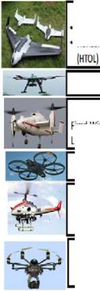
Figure 1 presents a classification [1] of UAVs.
* UAV Classification *
Flight Range:
-
• Low Flight Range: Less than 100 Km
* Medium Flight Range: Between 100-400 Km
' High Flight Range: More than 400 km
Endurance
-
■ Low Endurance: Less than 5 hours
-
■ Medium Endurance: Between 5-24 hours
-
• High Endurance: More than 24 hours
Rotary Wing
Quad-Helicopter
Unmanned Copter:
* VIOL Manoeuvrability
• High Maintenance
Multi-Copter:
* Lightweight/lnexpensive
• Vulnerable to Wind/Rain
Fixed Wing:
■ Long Range Endurance
• Horizontal Take-Off and Landing
Tilt Wing:
Fixed Wing and Vertical Take-Off and
Landing (VIOL) Combined __________
• Micro Weight: 0- 5 kg
• Light Weight: 5 -50 kg
■ Medium Weight: SO-200 kg
* Heavy Weight: 200-2000 kg
• Very Heavy Weight: Above 2000 kg
Wine Load
• Low Wing Load: Less than 50 kg/m2
■ Medium Wing Load: 50 1OO kg/m2
■ High Wing Load :More than 100 kg/m2
Flight Altitude:
■ Low Flight Altitude: Less than 1 Km
• Medium Flight Altitude: Between 1-10 Km
• High Flight Altitude: More than 10 km
Fig. 1. UAV classification
Let us consider the drone types.
-
- Drones . This term is commonly used to refer to remotely (autonomously) guided aircraft. This term also describes various vehicles including submarines or land-based autonomous vehicles. In fact, drones can be classified into three main types, according to their flying mechanisms, as described next.
-
- Multi-Rotor Drones : they are also known as rotary-wing drones. They are based on the Vertical Take-Off and Landing (VTOL) principle. Moreover, due to their maneuverability, they can hover over a fixed location, which allows them to provide a constant cellular coverage over certain areas. Therefore, multi-rotor drones can act as base stations at their intended locations with high accuracy and precision. However, their mobility is very limited and they consume large amounts of energy.
-
- Fixed-Wing Drones : these are more energy efficient than multi-rotor drones. This is due to their ability to glide and travel at a high speed, while carrying heavy payloads. The main drawback of fixed-wing drones is the need for a runway to take off and land, due to their Horizontal Take-Off and Landing (HTOL) nature. Another drawback is their inability to hover over fixed locations, in addition to their expensive software / hardware nature.
-
- Hybrid-Wing Drones : these are fixed / rotary wing drones that recently made it the market. This type of drones is able to reach the destination quickly by gliding over the air and hovering through the use of four rotors.
UAVs . A UAV can fly remotely / autonomously using a controller, mobile phone, computer or even a tablet. They are characterized by their autonomous flight capabilities and ability to operate over long distances with a secure live feed transmission. Moreover, UAVs control can be classified and divided into three main categories:
-
- Remote Pilot Control : known as operator static automation, where all decisions are made by a human remote operator.
-
- Remote Supervised Control : known as adaptive automation. It offers the drones the ability to launch and carry out a given mission process independently, while allowing for human intervention, if needed.
-
- Full Autonomous Control : known as system static automation, where drones can make all required decisions for a successful mission completion, without the need for any human intervention.
UAS . These include UAVs and drones, and the operators controlling them. A UAV is a type of UAS since it refers to a controlled vehicle or aircraft.
RPA . RPA stands for Remotely Piloted Aircraft, which requires intensive skills and training over a long period of time (a couple of years) to operate and control these complex flights.
Drones are used to track down suspects using the aerial bird watch view. This proved to be cheaper and more maneuverable than a helicopter. In fact, drones will soon have the ability to contain thermal, motion, and night vision detection, which can be used to track down suspects at any time of the day. Furthermore, drones can be used to enhance traffic efficiency by offering quick response and identification of road conditions. This helps in avoiding traffic congestion, and in responding to a traffic accident or emergency. Moreover, these drones can be used for surveillance purposes, with the ability to detect suspicious targets hidden within public domains, which proved to be more flexible than fixed cameras. The reason is due to their capability in identifying and recognizing suspects from their height, size, and facial recognition, and thus, making it very difficult for suspects to hide in public.
In fact, according to BBC News, the UK prison service and the police are investing their resources to stop drone pilots from flying drugs, mobile phones, blades, knives, Subscriber Identity Module (SIM) cards, Universal Serial Bus (USBs) etc. into prisons. These drones were being flown over walls and physical barriers. As a result, reports revealed that almost 3m may possibly be spent on the newly assigned task force to overcome this problem. As a result, due to the autonomous and operational nature of drones, they became more and more adaptable and operational. This reduces and replaces the use of choppers, decreasing the response time and needed resources. Drones are capable of capturing a live bird-view of different types of incidents ranging from crimes, theft, to even riots. This leads to a firmer response with a more enhanced plan due to the ability to identify suspects while locating and tracking them down before arresting them. Also, UAVs can be used by the police and other agencies to gather crucial information in dangerous situations with less manpower and money.
Military applications . UAVs became the perfect choice for military usage, especially for intelligence and reconnaissance purposes per-forming Surveillance, Target Acquisition and Reconnaissance (STAR), Joint Surveillance Target Attack Radar (JSTAR), Reconnaissance, Surveillance and Target Acquisition
(RSTA) tasks. Their deployment is a key part to counter insurgency and terrorism, offering the ability to Track and Identify Dismounted Personnel (TIDP) in urban environments, especially in Areas of Operation (AO).
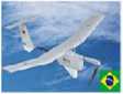
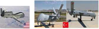
Figure 2 presents a summary about several Drone / UAV types being used in overt/covert military operations, which are described next.
Military UAV Classification
-
1. Miniature-UAV:
■ Scanning Micro-UAV
-
■ <=25 Kg
-
• < 1200 HAGL
-
■ < 100 knots
-
■ LAIE
-
2. Small-UAV;
■ Scanning ■10-50 KG •<3500 HAGL
-
• LALE
-
■ < 250 knots
-
3. Medium-UAV:
■ Scanning
-
■ Surveillance
-
■ 50-500+ KG
-
• Strike Capable
-
• FL180
-
■ MALE
-
4. Tactical-UAV:
-
• Surveillance
-
■ Reconnaissance
-
■ Strike Capable
-
• =>500 KG
■ FL180-FL300t
-
• Autonomous
UACV
-
• MALEIHALE
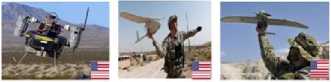
WASP
T*Hawk (Tarantula Hawk)
FT*100 Horus
iX
Bayraktar
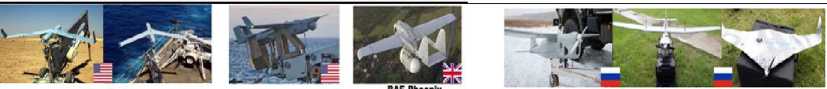
ScanEagle
RQ-21 Blackjack
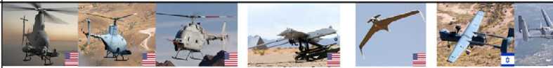
RQ-5 Hunter
MQ-8 FireScout Variants А, В A C
EADS Harfang
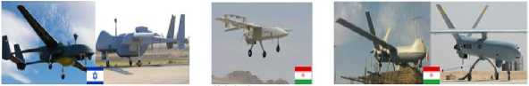
MQ-1S Predator
RQ-4S Global Hawk
ANKAS ANKAS
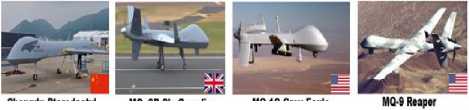
Chengdu Pterodactyl MQ-9B SkyGuardian
MQ-1C Grey Eagle
5.Stealth-UAV:
-
■ Reconnaissance
-
• Autonomous UACV
-
• Strike Capable
-
■ High,Ultra High
Speed
-
■ HALBMALE
-
■ FL300
Taranis
RQ-170 Sentinel
Dassault nEUROn
EADS Talarion
Kratos XQ-58 Valkyrie
BAE Mantis
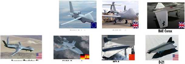
EADS Barracuda
|er
* HAGL: Height Above Ground Level
-
• FL Flight Level
-
• LALE: Low-Altitude Long-Endurance
-
• MALE: Medium-Altitude Long-Endurance
-
• HALE: High-Altitude Long-Endurance
Fig. 2. Military drone/UAV classification [2]
The tremendous increase in the use of drones and UAVs led to a new aviation era of autonomous aerial vehicles in both the civilian and military domains, offering numerous benefits including economical, commercial, industrial, mainly due to their autonomous, flexible and easy-to-use nature, with low cost and energy consumption. However, their use led to the rise of many security, safety and privacy issues, which were manifested through various cyber-attacks, threats and challenges, listed and explained in this paper. Also, it was presented a holistic view of the drones / UAVs domains and provided detailed explanation and classification of their use in various domains and for different purposes, in addition to the different lethal / non-lethal security solutions as part of drones / UAVs countermeasures. Moreover, successful experiments to detect, intercept and hijack a drone through either de-authentication or jamming were highlighted, based on
Сетевое научное издание «Системный анализ в науке и образовании» Выпуск № 3, 2022 год realistic scenarios that follow the traditional hacking cycle and hence, confirming the ease with which drones could be intercepted, especially in terms of UAV communication channels.
In this context, different security suggestions and recommendations were proposed to ensure a safer and more secure use of drones and UAVs. Finally, due to the alarmingly increase in the use of drones by terrorists, further studies and experiments on how to prevent and counter the UAV threats, imposed by terrorists, will be performed and conducted as part of future work.
The advancement in developing one of single rotor helicopters was historically much faster than the development of full-scale coaxial helicopters. This is predominantly because of the staggering intricacy of their swash plate design mechanisms. Be that as it may, the upside of coaxial was acknowledged for maritime vessels and unmanned vehicles, where space is quite restricted. In this design, one propeller is situated over the other on the same shaft and the rotors turn in inverse directions, which make the requirement for a tail rotor unnecessary. Therefore, it makes the helicopter much more compact. A coaxial UAV utilize the residual torque, due to angular speed difference between the two rotors, for the helicopter to move right, left or vertical.
Bio-inspired strategies for aerial–aquatic locomotion
Current Micro Aerial Vehicles (MAVs) are greatly limited by being able to operate in air only. Designing multimodal MAVs that can fly effectively, dive into the water and retake flight would enable applications of distributed water quality monitoring, search and rescue operations and underwater exploration. While some can land on water, no technologies are available that allow them to both dive and fly, due to dramatic design trade-offs that have to be solved for movement in both air and water and due to the absence of high-power propulsion systems that would allow a transition from underwater to air. In nature, several animals have evolved design solutions that enable them to successfully transition between water and air, and move in both media. Examples include flying fish, flying squid, diving birds and diving insects. The biological literature on these multimodal animals abstract their underlying design principles in the perspective of building a robotic equivalent, the Aquatic Micro Air Vehicle (AquaMAV). Building on the inspire–abstract–implement bioinspired design paradigm, can identify key adaptations from nature and designs from robotics.
Most animals use different forms of locomotion to move through a varied environment. This allows them to adapt to find food, escape threats or migrate, while minimizing their energetic cost of locomotion. To do so, animals must use the same locomotor modules to perform specialized tasks that often have opposed requirements. For example, an animal diving into the water to hunt requires a structure that is as lightweight as possible for efficient flight, whilst still being structurally strong when impacting the water’s surface. The complexity of biological systems makes them difficult to replicate artificially, but meeting the demands of two modes of locomotion in a single robotic system has been done. Bioinspired robots have been presented that can both fly and move on land, either by jumping or by walking. Other robots take cues from amphibious locomotion in nature and can move on land and in water.
Transitioning between flying and swimming presents several key design challenges. To analyses them, it is helpful to examine the robot’s mission in the context of distinct mission phases (Fig. 3): first the robot has to perform high efficiency flight, then must transition from air to water when at a target. After transition, it must spend a period moving beneath the surface for water sampling and video footage, before transitioning back to flight from the water [3].
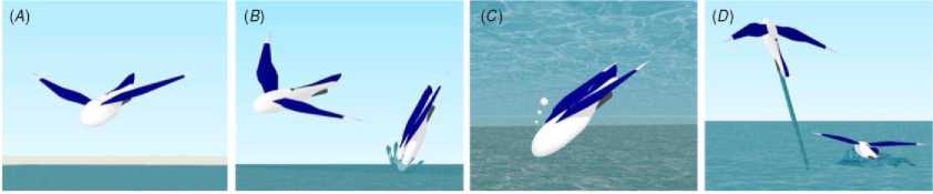
Fig. 3. Every stage of an aerial–aquatic mission poses different key challenges for an AquaMAV: (A) dry flight, (B) water entry, (C) submerged movement and (D) water exit
The key challenge when in flight is the minimization of power requirements. This is achieved by maximizing the aerodynamic efficiency of the vehicle, which becomes more difficult at the small scale. Micro Aerial Vehicles typically operate in the Reynolds number range 104–105, and at these low flight Reynolds numbers the aerodynamic efficiency of flight is reduced due to increased viscous effects, and air perturbations will have a much more significant effect on the vehicle. Furthermore, the design constraints of flight must be satisfied simultaneously with those imposed by the need to swim. These additional constraints come from the need for dual propulsion modes, a stronger superstructure and waterproof design, all of which add to the flight mass.
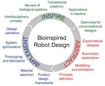
The Inspire–Abstract–Implement paradigm for bioinspired robot design was introduced (Fig. 4), and fo- cus on the Inspire and Abstract phases of the process, examining and evaluating the performance of animals with a view to advancing robotics.
\MSP/^
Bioinspired Robot Design
Design validation
Biomimetic exploration
Experimental analysis
System optimization
Interdisciplinary curiosity
Applications in robotics
Openness for unconventional designs yr Modelling and simulation
Principle definition
Prototyping and fabrication ^"^
Material selection Product design frameworks
Translational
Review of creativity biological systems
Fig. 4. The Inspire–Abstract–Implement paradigm for bioinspired robot design
Over 40 species of marine fish have evolved the ability to perform extended flights above the water’s surface. These animals leap from the water’s surface and glide on enlarged pectoral fins (Fig. 5(A)), and are capable of spending over 40 s airborne.
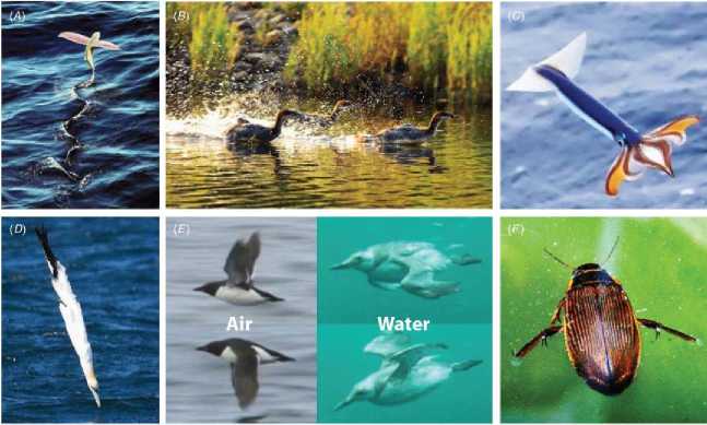
Fig. 5. Strategies for aerial–aquatic locomotion: (A) two stage transition: flying fish, (B) hydroplaning: ducks, (C) jet propulsion: flying squid, (D) plunge diving: northern gannet, (E) morphing wings: common guillemot, (F) Foot propulsion: great diving beetle. Images used with permission from: US NOAA (A), Cappi
Thompson (B), Kouta Muramatsu (C), David Tipling (D)
Beneath the water the oceanic flying fish (family Exocoetidae ) are conventional swimmers, with their pectoral fins folded against their body. But when deployed in flight, these fins form high performance membranous wings. The wing flexibility also allows the fish’s body to rotate relative to its wings, providing further stability, particularly during emergence. The wing itself has pointed tips, which will reduce induced drag without increasing the root bending moment (which must be supported by muscle tension). The wing membrane is supported by many cartilaginous fin rays, with an L-shaped cross section.
This structure will enhance wing stiffness to weight ratio, but also allows tessellation on folding. The deployed wing is also given a non-smooth surface by this structure, which may also offer aerodynamic performance benefits in the low Reynolds number range.
While each animal has a distinct set of locomotion modes, several recurring principles can still be identified. For example, all animals employ a form of hydrophobicity to shed water or retain air, most feature some means of buoyancy control and all fold or modify their wing structure when moving in the water. Here we select from our review several bioinspired design principles, and propose a that a vehicle capable of a jet propelled takeoff, utilizing folding wings and able to plunge dive is the best route for realizing AquaMAV (Fig. 6).
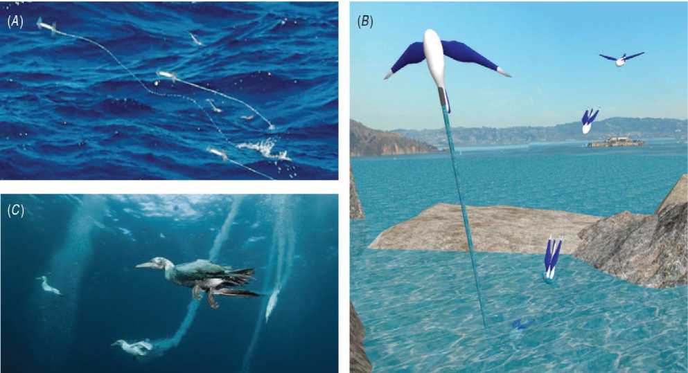
Fig. 7. Bioinspired principles for AquaMAV: plunge diving by gannets (A), jet propelled takeoff by squid (B), plunge diving AquaMAV concept sketch [3]
The most challenging part of an aerial–aquatic mission is to reinitiate flight after diving. A vehicle that has been designed for effectively plunging would still need to be minimally buoyant, in order to maximize its dive depth. This would then make a taxiing takeoff near impossible due to the wave drag acting on a vehicle with high displacement. Flying fish and birds are able to leap directly from the water, and avoid taxiing takeoff complications. However, flying fish must first reach submerged speeds of around 20 body lengths per second. This performance represents an order of magnitude increase over what has been achieved up to this point by biomimetic underwater robots, and the power availability of small-scale mechanical actuation systems cannot yet match that of bird and fish muscle, without prohibitive sacrifices in frequency response or stroke rate.
This will make it hugely difficult to takeoff from the surface of the water by flapping, or biomimetic swimming. However, water jet propulsion has a very rapid thrust response that is difficult, if not impossible to achieve using propellers, flapping wings or beating tails, and as such is ideal for an impulsive takeoff. Compared to flapping and beating, a full power squid escape jet is also mechanically simple. Importantly, it can continue to produce thrust when clear of the water surface and its associated high drag, unlike fin based water surface jumps, which rely on reaction forces from the surrounding fluid.
The high hydrodynamic drag in water makes it uneconomical to launch directly through the surface, and it is better to accelerate when out of the water. However, leaping directly out of the water is far more robust, because it does not rely on a clear expanse of water to accelerate in. In this sense, the flying squid’s jet propulsion strategy achieves the best of both worlds, by being able to produce thrust continuously while transitioning between media. This allows an airborne transition stage without the need for the surface taxiing phase required by birds and fish, and when on water, a jet-propelled method of launch is also robust to environmental conditions, requiring far less takeoff area than taxiing takeoffs (see Fig. 8).
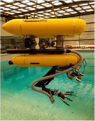
Michigan University’s aquatic UAV The goal: aerial and underwater operations
The successful water-to-air transition aquatic UAV
(A)
(B)
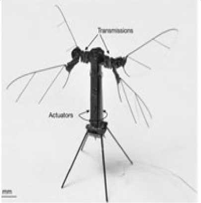
Insect-inspired UAV
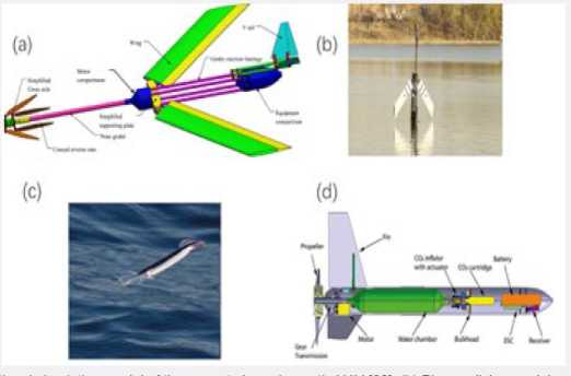
(a) Computational simulation model of the gannet shaped aquatic UAV. (b) Plunge-diving model made by Beihang. (c) Photo of squid. (d) Squid-inspired UAV
(C)
(D)
Fig. 8. Examples of Aquatic Unmanned Aerial Vehicles [3-8]
One mission an AquaMAV would be uniquely able to perform is the collection and rapid return of a water sample from a hazardous area. Because a sample return mission only requires one takeoff from water, the authors suggest that the energy required to create the jet thrust could come from a ‘single-shot’ system using compressed air. The propellant water mass can then be collected in situ after diving into the water, to keep flight mass down. While the energy density of such a system would not match that of a combustible rocket, compressed gas is far less hazardous to its environment. Solid rocket fuels are highly controlled by regulations, are difficult to miniaturize and many situations (an oil rig accident, for example) would preclude the use of fire by exploring robots.
The water-air transition, control system for multi-UAVs, take-off and landing processes, and aquaticaerial communications problems are must discussed as well. Biomimetics have been paid much attention to as well. They developed a lot in recent years which inspire designers to develop biomimetic aquatic UAVs using the revolutionary advantages. Many biomimetic prototypes have been tested to have cross-domains abilities though they cannot dive too deep nor dive too long underwater. But bio-inspired aquatic UAVs will contribute a lot to the ultimate realization of a fully functional aquatic UAV. Like batoid-shaped aquatic UAVs. In the water, the fins will move in a certain way to generate propulsions while in the air the fins can be used as wings to provide lift. This is a promising design for aquatic UAVs and bio robotic aquatic UAVs. There are also many other good designs that can achieve the amphibious goal initially. Most of practicable designs are plane-based aquatic UAVs, which pay more attentions to flying rather than diving. However, there are few good designs in submarine-based aquatic UAVs.
So further work can pay much attention to diving processes. For instance, a submarine equipped with a balloon can fly and dive, but the feasibility is unknown. Another problem with the existing designs is that designers do not pay much attention to flapping wings. In a big aquatic UAV, flapping wings are inefficient, but for small-sized aquatic UAVs, flapping wings are efficient and can adapt to the air and water conditions. The solar cells can provide power for small-sized aquatic UAVs. So small-sized insect-inspired aquatic UAVs with flapping wings should be paid more attention in the next few years. The developments of fully functional aquatic UAVs are promising and achievable. Many partially functional aquatic UAVs have proved the feasibility of a real one.
Bio-inspired vehicles are currently leading the way in the quest to produce a vehicle capable of flight and underwater navigation. However, a fully functional vehicle has not yet been realized. Birds and fish have many features that work together enabling them to fly and swim, respectively. If we simplify the problem to the main forces acting on birds (lift, weight, thrust and drag) and on fish (buoyancy, weight, thrust, drag) we observe that the differentiators are lift and buoyancy. The discussion about forces can be further simplified by noticing that fish and also underwater mammals have a large range of weight/size ratio which indicates that weight is not a major constrain in their mechanics of locomotion. On the other hand, a bird’s weight is a critical constraint in their mechanics of locomotion. We will not consider drag in our simplified analysis, as both birds and fish have mastered drag reduction through clever aerodynamics and streamlined bodies. The question is as follows: can we combine both mechanisms (flight and swimming) into a single vehicle and be able to perform equally well in both mediums during extended periods?
Among all the requirements for a vehicle to perform air and underwater operations, the transition between both mediums is perhaps the most challenging. For birds, this is done by diving directly into water or landing in water and then diving. For fixed wing vehicles, landing and taking off from water has been successfully demonstrated (seaplane). But it is the process for submersion after landing or the process for taking off after returning to the surface that adds complexity and duration to the operation. While such a vehicle has not yet been fully realized, and it wouldn’t be considered a seamless transition if it did, the expectation is that such vehicle is possible and it will be fully functional in the future.
An alternative to a fixed wing vehicle is that of a single or multi-rotor vehicle [9]. One of the advantages of multi-rotor vehicles is their VTOL (vertical take-off and landing) capability. The innovation demonstrated here redefines multirotor VTOL operations to achieve seamless transition between air and water. It uses dual propellers/motors in each vehicle-arm with a column gap between the top and bottom motors that facilitates such transition as described by the sketch in Fig. 9. Each propeller is individually addressable during the seamless transition.
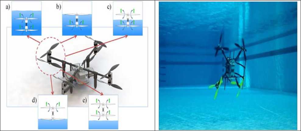
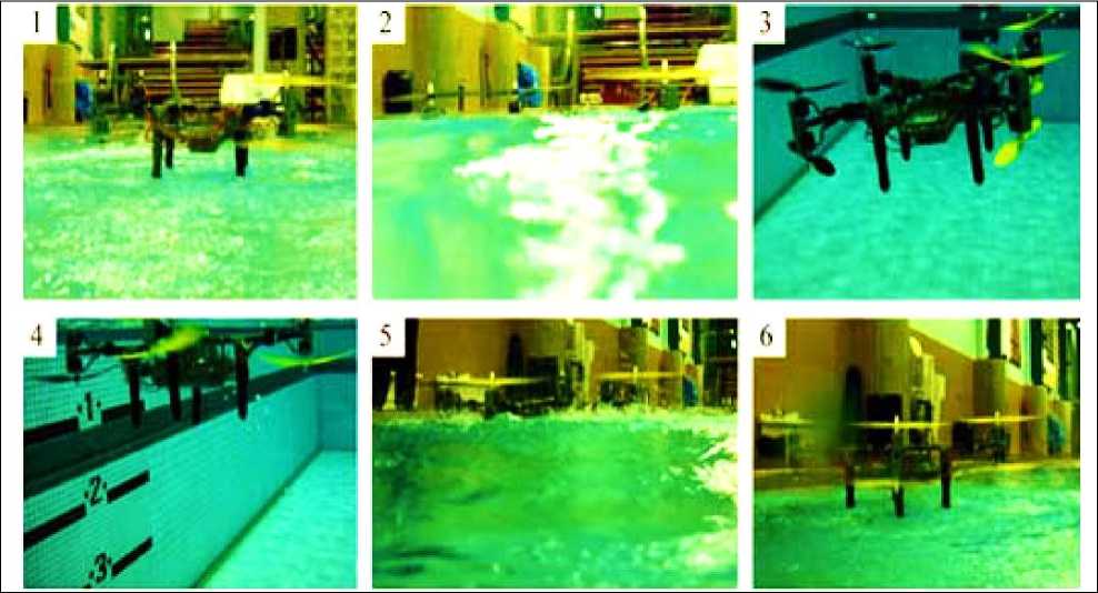
Fig. 9. (left up) Sketch describing the mechanism used for seamless transition between water and air; (right up) Tethered air/underwater multirotor prototype, during horizontal underwater cruise mode; (down) Untethered air/underwater multirotor prototype, performing the air to water transition (1-3) and the water to air transition (4-6)
The dual-propeller system is fully reversible allowing air to underwater or underwater to air transition. The water to air transition is shown in Fig. 9 (down). As the vehicle approaches the surface (water/air interface) both propellers (top/bottom) are generating lift. While going through the interface, the top propellers will momentarily slow down to ensure a smooth transition, and as soon as they are clear of the water, they can accelerate to entrain air and generate lift again. Similarly, as the bottom propellers reach the surface, they will momentarily slow down to ensure smooth transition, and when they clear the water interface, they can start to generate lift again. The advantage of slowing/stopping the propellers right at the air/water interface is to prevent a spike in drag from this complex interaction, where no positive forces can be generated. The sequence of events in Fig. 9 (left up, a-d) is performed in under two seconds, thus realizing the seamless transition. The photograph sequence in Fig. 9 (down) shows the actual vehicle built (Naviator1) during air to water and water to air seamless transition [9].
The majority of a bird’s propulsion system works by a flapping mechanism which generates both lift and thrust. Vehicles capable of flight need to generate these two forces. While the flapping mechanism has been difficult to reproduce beyond the smaller scales, two other methods are widely available. One, produced by fix wing airplanes, uses the wings to generate lift and their propellers to produce thrust. The other, produced by VTOL vehicles (single rotor and multi-rotors), uses the propellers to generate both lift and thrust and the vehicle pitching angle determines how much of the generated force is used for lift and for thrust. This capability from propellers in multi-rotor vehicles will be fully exploited here.
Fish and aquatic mammal propulsion systems can be quite diverse, but in general they all need to generate thrust. In a few species, where their body system cannot be neutrally buoyant, secondary lift forces are required. Underwater vehicles have a similar requirement to be nearly neutrally buoyant, and to generate thrust. This force is commonly generated with a propeller.
Initially, one might not expect that the same propeller system can be able to operate in air in vertical mode and in water in horizontal mode. But as it turns out, not only it is possible but it is the preferred state. Multi-rotor vehicles in air operate in “vertical” mode where part of the force generated by the multi-rotor system is used to carry its weight. When the vehicle hovers, the propellers are vertically aligned, and when the vehicle travels horizontally, the vehicle has a small pitching angle (< 15-20°). A multirotor traveling at higher pitching angles can be considered to be in acrobatic mode and it is more unstable.
Multi-rotor vehicles in water have not been considered to date. Thus, their operation is not known and needs to be evaluated. As previously discussed, a horizontal-aligned propeller is desired in water, as no lift is needed in this medium for a neutrally buoyant vehicle. We have built such a vehicle to test if a multi-rotor vehicle can operate in water in “horizontal” mode. A typical image of the vehicle operating in this mode is shown in Fig. 9 (right up). The tests show this as the preferred state for multiple reasons. First, having the four dual-propellers all aligned nearly horizontally means that the majority of the force being generated is thrust. The vehicle control method is also similar to a multirotor in air, where pitch, roll and yaw are obtained by varying the power to individual arms in the vehicle. However, these are reversed due to the orientation of the vehicle. Also, for our neutrally buoyant vehicle, when travelling horizontally there is no dominant de-stabilizing force. This is critical, as such force would render horizontal mode not possible (or very unstable). In air, unfortunately, the weight of the vehicle is a de-stabilizing force that the propellers and orientation of the vehicle need to be constantly balancing to maintain control flight.
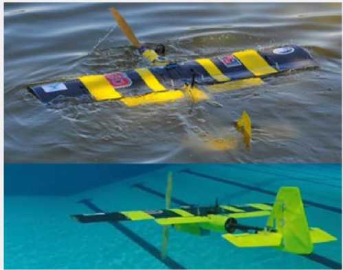
In nature, locomotion strategies are usually highly optimized for one type of environment. But the animal domain has some members that seem to have mastered the transition between those different environments. The northern gannet for example, a bird of 2m wingspan and 3kg body weight, plunge dives 10m under water, hitting the water surface at up to 100km/h, to hunt fish. Another example are penguins. Unable to fly, and with limited mobility on land, penguins are nevertheless very agile underwater, with speeds up to 5.3m/s allowing them to jump from water to land. Modern UAVs can be split into three categories based on their operation principle: fixed-wing aircraft, rotor craft and lighter than air vehicles. Lighter than air vehicles are difficult to submerge under water because of their high buoyancy. In comparison, rotor craft tend to have higher densities, but suffer from limited range in both media and dynamic capabilities underwater. A fixed-wing design, based on flight efficiency and relative simple actuation concept in Fig. 10 demonstrated [5,10].
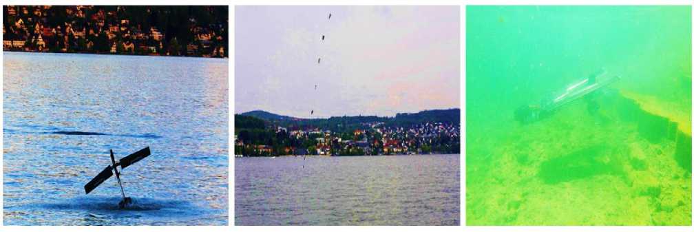
Fig. 10. Dipper platform in different configurations (from left to right): (i) emersion phase, (ii) sequential image during dive-in and (iii) underwater
The main challenge for a vehicle operating in both air and water is the large difference in density between the two media. On one hand, the conductivity and corrosive properties in combination with the high loads subjected to the vehicle by water require the system to be sealed, robust and have minimized displaced volume to reduce buoyancy. On the other hand, fixed-wing flying systems require large lifting surfaces and a minimized mass to remain airborne. This leads to a contradicting set of requirements.
A system which can operate dynamically in the air, during transition phases and underwater with the necessary robustness and capability to carry at least small payloads has yet to be developed. Our proposed solution is a fixed-wing UAV with wing-folding capabilities, powered by a single electric motor (Fig. 11). The potential benefits and promise offered by UAVs in a multitude of applications have captured the attention of both the military and commercial sectors. It is imperative to address UAV mishap rates now so that their full potential is realized. When technology changes rapidly or new and radical designs are introduced, previous accident data may no longer be valid. This assessment of UAV mishaps using a validated hierarchical model of human error linked to the 7 domains of HSI has identified recurring human factors trends which need to be addressed in order to make UAVs more viable in the near and distant future. As noted by Weeks: “because UAVs are just beginning to be adapted into the U.S. military, human factors research is needed not only to help resolve the controversy over operator qualifications but also to support programs similar to those for manned aviation including physical standards, simulator training, and crew coordination training.” Rather than being the solution to human error, UAVs have instead opened a new and critical chapter in aviation human factors [6].
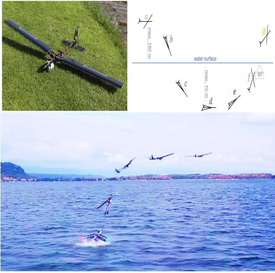
Fig. 11. (left up) Prototype in flight configuration; (right up) Full cycle of flight (a), dive (b; c), swim (d; e) and emersion (f; g); (down) Emersion phase (f; g) followed by flight (a)
The target operation flow can be seen in Fig. 11 (right up). The system flies (a) at cruising speed. To dive (b) the wings are folded backwards parallel to the fuselage and the motor changes direction to drive the underwater screw. Once the impact on the water surface is detected through the pressure sensor, the system opens the wings approximately 10 degrees to increase pitch authority and dives to a preset depth (c), where it levels out (d). To emerge, the system pitches upwards (e) and opens the wings fully (f) to reach the water surface at a preset egress angle of approximately 80 degrees.
Once the surface is detected by the pressure sensor, the motor is set to full thrust with the aerial propeller and the system pulls itself out of the water (g), giving the pilot time to take control for manual flight. Alternatively, the pilot can take over control once the system breaks through the surface, as soon as connection is established. The necessary precision in timing and control of the whole transition phase is not yet sufficient for a jumping dive-out. Therefore, further investigations into the control of the ESC and the general control of the process are necessary to optimize the propulsion system. Nevertheless the system is capable of transitioning between the two media in less than 2 s, resulting in a dynamic and reliable dive out (success rate above 80%), with the most common problem being the direction change of the motor due to issues with measuring the orientation of the rotor with respect to the magnetic field by the ESC in water. In this case the system falls back into the water and can make another dive-out attempt.
To facilitate the testing set up and increase safety, the system started in phase c (underwater). The resulting depth profile measured by the pressure sensor. After staying submerged for about 10 seconds, reach- ing a depth of almost 3 meters, the system rose to the water surface in an angle of 80 degrees and once it broke through the water surface, continued the dive out sequence (Fig. 11, down).
The system is agile and efficient in the air as well as dynamic underwater achieved by an optimized propulsion system and actuation concepts for both areas of operation. The folding wing concept provides a reduced cross-sectional area for the dive-in phase and a shift of the center of lift/buoyancy with respect to the center of mass for ideal trim in all operation modes.
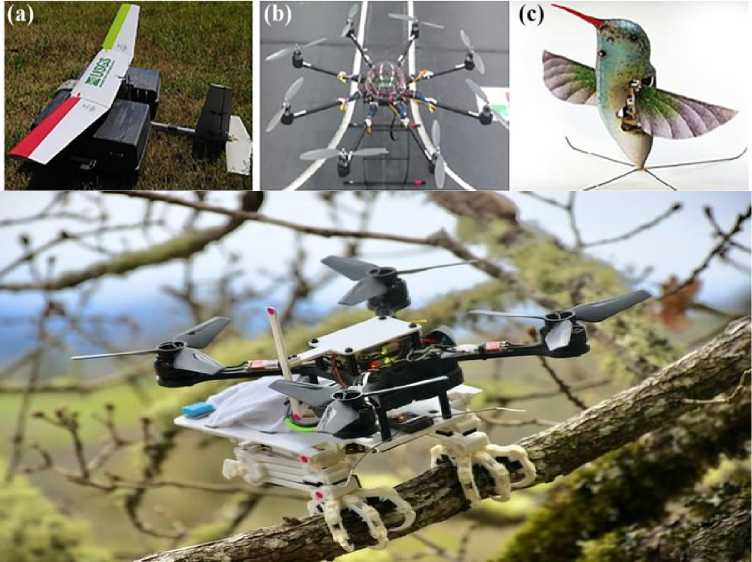
Locomotion in unstructured terrain is a significant challenge to miniature robots operating in an outdoor environment, often requiring operation in water, air and on the ground. The challenges of multimodal locomotion are addressed in many ways in nature, by animals that can adapt their structures and behaviors to address the changing requirements of movement in air and water. Plunge diving birds are a particularly striking example of this, most notably the northern gannet, a predatory seabird able to dive into the water (Fig. 13, a,b) at speeds of up to 60 miles per hour by sweeping its wings fully backward, in order to catch fish beneath the surface.
№ № (с) №
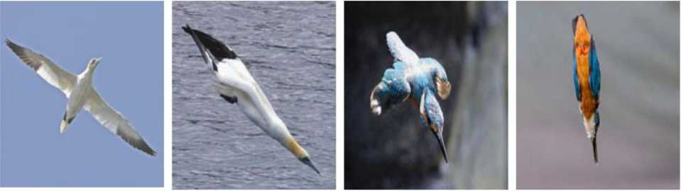
Fig. 12. Plunge diving in nature. (a) Northern gannet (Morus bassanus, 3 kg mass) in flight, and (b) with folded wings about to dive into the water. (c) Common kingfisher (Alcedo atthis, 0.03 kg mass) in a dive with wings partially folded and (d) with wings fully folded. Images reproduced under a creative commons licence, courtesy of: Andreas Trepte (a), Mike Pennington (b), Ryan Cheng (c) and Andy Morffew (d )
Such plunge diving behavior is also observed in pelicans and boobies, and even far smaller birds such as the common kingfisher (Fig. 12,c,d). Reproducing the ability to dive directly through the water surface in a miniature flying robot would allow unique operation in a wide variety of environments, such as tidepools, wetlands or canal systems, enabling autonomous monitoring of contaminants and ecosystem health. However, order to dive into the water, a vehicle must be able to accommodate the increased structural loads, fluid inertia and drag encountered underwater, without compromising the weight and lifting area requirements of flight. To achieve this, a novel robot, called the Aquatic Micro Air Vehicle (AquaMAV) developing that is capable of aerial and aquatic locomotion, able to dive directly into the water at high speeds to achieve initial depth, subsequently retaking flight using a high-powered burst of thrust.
Recently, quadrotor platforms able to move underwater have been demonstrated, using aerial propellers to produce thrust in water. Both robots use aerial propulsion systems underwater, which means that aquatic propulsion will be highly inefficient, owing to the larger torque loads on the motors when in the water. Generally, quadrotors cannot match the efficiency of a fixed-wing vehicle in forward flight, as they must use significant energy to balance their weight, whereas a vehicle producing aerodynamic lift can use less power while moving forward. Quadrotors will also likely be inhibited by the presence of surface waves during takeoff. Instead was proposed that a robust means of take-off from water is an impulsive leap, thrusting through surface perturbations, as demonstrated in Fig. 13.
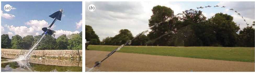
Fig. 13. Jet propelled launch by a previous AquaMAV prototype. (a) The AquaMAV uses a pressurized water jet to escape the water. (b) Timelapse of an AquaMAV launch, with wings opened in the final frame
By folding its wings before take-off an AquaMAV can reduce drag and quickly reach flight speed, before deploying wings and transitioning to flight, in a manner analogous to multimodal jump gliding robots on land. The AquaMAV was launched from an elevated position and steered to impact in front of a camera placed at the water level, with the wings folded and throttle cut manually by a remote operator. While the flight speed cannot be accurately measured, an estimate of the final impact velocity can be made from the final frames of the sequence in which the vehicle flight path is near vertical, with the AquaMAV itself providing a reference length.
Figure 14a shows [10] a composite image of a dive into water, recorded with a static camera at 120 frames s – 1.
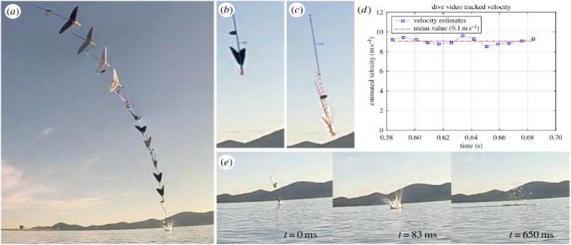
Fig. 14. Preliminary flight test of the AquaMAV outdoors. (a) Composite image of a dive into water, with frames 83 ms apart. The impact velocity was estimated from the later video frames. (b) Calibration frame using vehicle length as reference. (c) Final frame showing tracked points. (d) Velocity estimate from tracked points. (e) Image of the AquaMAV at the point of impact with the water. (f) Image of the AquaMAV fully immersed after a dive [4]
The AquaMAV was launched from an elevated position and steered to impact in front of a camera placed at the water level, with the wings folded and throttle cut manually by a remote operator.
The vehicle speed was estimated using a software automatic tracking routine (OpenPhysics Tracker) which yielded an approximate impact velocity of 9.1 m / s (Fig. 14, b–d).
The vehicle was undamaged by the pictured impact, although it is noteworthy that during a later flight an accidental water impact with open wings resulted in the destruction of one of the wing hinges. For future flights a compact sensing system is under development to allow recording of airspeed and inertial measurements during dives.
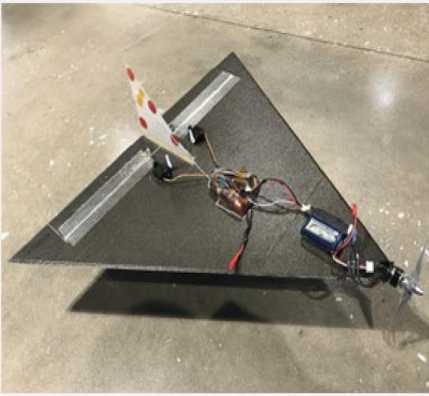
Example. Unmanned aerial-aquatic vehicles (UAAVs) have the potential to dramatically improve remote access of underwater environments. In particular, fixed-wing UAAVs offer a promising means of enabling efficient locomotion in both aerial and aquatic domains through the use of a lifting surface. A propeller-driven delta-wing unmanned aerial-aquatic vehicle design was presented and demonstrated that, given the right parameter values, successful water-exit could be achieved for a given maximum thrust avail- able in water and air. However, unlike other approaches which rely on novel propulsion mechanisms to achieve water-exit, the design relies on the availability of closed-loop feedback control to enable multidomain locomotion. A software-only water-exit solution had the potential to greatly reduce the cost and mechanical complexity of hybrid aerial-aquatic vehicles. A feedback control approach for enabling a water-to-air transition applied. The fully instrumented system can be seen [4] in Figs 15-17.
maneuver
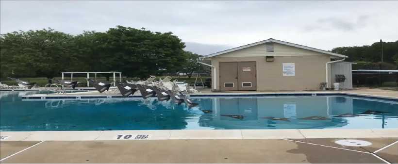
Fig. 17: Successful water-exit to 45-degree prop-hang. Time-step between underwater frames is 1.67s while the time-step between air frames is 0.25s
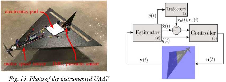
prototype. Figure shows the main electronics pod, motor speed sensor, IMU, and pressure sensor
Fig. 16. A depiction of the closed-loop control system used to execute a water-exit
Remark . In Fig. 16 (a) provides a feasible multi-domain water-exit trajectory, (b) represents the hybrid control system, and (c) is the state estimator for estimating the continuous system state and the mode.
To waterproof the electronics, a waterproof pod was constructed by vaccuum forming a thin plastic shell over the electronics. The overall weight of the instrumented vehicle was 375 grams. To instrument of the vehicle, a HobbyWing RPM sensor along with the Bosch BNO055 IMU and the TE MS5837-30BA pressure sensor applied. A custom autopilot board consisting of an ATMEGA32U4 for sensing and actuation and a Gumstix Overo Cortex-A8 for executing all the control and state estimation on-board. Design relies on the availability of closed-loop feedback control to enable multi-domain locomotion. A software-only water-exit solution had the potential to greatly reduce the cost and mechanical complexity of hybrid aerial-aquatic vehicles. A feedback control approach for enabling a water-to-air transition.
Figure 17 shows a successful water exit, where the vehicle transitioned to a flight regime where it Multimodal robots are able to move effectively in different media (water, ground, air) and transition between them. This remarkable capability, inspired by nature, allows for the advantages of different types of robots to be combined in a single platform. Thus, it becomes possible for the same robot to cover long distances and fly over obstacles, like an aerial vehicle, and move efficiently underwater for long periods of time like a submersible. Aerial-aquatic robots, specifically, could vastly facilitate operations involving water sampling or underwater surveying, which currently rely on manpower (e.g. hand-dropped sensors, rope-access to spaces under oil rigs) or on the complex integration of different vehicles (e.g. ships carrying deployable submarine robots). Using a single multi-purpose vehicle for such tasks instead would lead to more effective data collection as well as improved safety and reduced costs. However, effective operation in – and transi- tioning between – vastly different mediums (water and air) presents a considerable challenge, which continues to hinder the development of aerial-aquatic robots for real-world applications.
Contributions include the following: (i) a novel approach for robotic water sampling, that is simpler and better suited for field testing than available methods, (ii) development of communications, electronics and control frameworks for a symbiotic dual-robot system, (iii) implementation of a new prototype (MEDUSA: Multi-Environment Dual-robot for Underwater Sample Acquisition, shown in Figs 18-20) validating the proposed concept, and (iv) demonstration of the operation of the new system in both a lab environment and outdoor field tests.
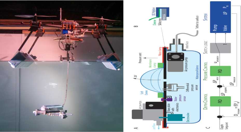
Fig. 19. A. Side view of the underwater pod with its main internal components. B. Seal clamp structure. C. Depth control schematic
Fig. 18. Photograph of the MEDUSA system: the multirotor robot is floating, while the pod has been partially uncoiled and is moving underwater
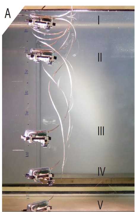
Fig. 20. Vertical actuation and depth control results
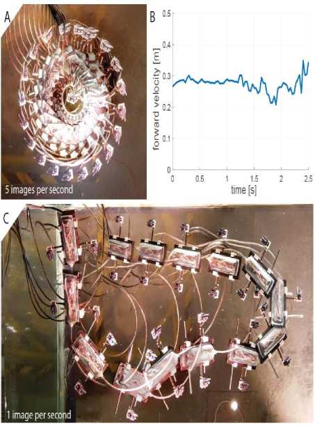
Fig. 21. A. Composition showing maximum rotational control of the robot at 100_/s. B.
Manual control of the horizontal motion of the robot moving forward, turning and returning to base. C. Maximum velocity of the robot with jet thrusters at 100%.
Results show that the jet-based actuation provides sufficient thrust, leading to a manoeuvrability well-suited to the types of missions envisaged for the robot. As shown in Fig. 9 (left), the pod can reorient itself rapidly and perform horizontal turns at up to 100 0/s, as well as reach given target locations within the range allowed by the tether, reaching a speed of up to approximately 0:35 m s – 1 (cf. Fig. 21).
Outdoor field tests were performed on a lake, surrounded by dense forest (cf. Fig. 22).
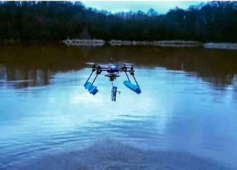
Fig. 22. (Left) The robot is remotely manoeuvred into a confined space with a side opening of 30 cm (Right) The flying dual-robot platform shown during a take-off
The vertical motion of the underwater pod is controlled through pressure-based inflation and deflation of a soft membrane. An important preliminary step is to establish whether this type of actuation mechanism is adequate for stable depth control. To evaluate this, we fed the pod a number of differential pressures setpoints and observed the resulting changes in differential pressure and volume of the deforming membrane. This is equivalent to testing the system with only the inner loop ‘pressure control’ component of Fig. 3.C active. Experiments were conducted outside the water with the pod at rest, so as to provide a clear view of the inflating membrane. The volume of the membrane at each time step was computed based on video footage.
The water conditions were calm, but there were gusty winds. One of the most critical aspects of an aerial-aquatic robot is the transition from air to water and vice-versa. We successfully demonstrate multiple landings and take-offs from the water of the quadrotor carrying the coiling unit and pod. The downwash of the propellers does not create significant spray during take-off and in general no significant difficulties were encountered.
The tests suggest that the robotic concept can function reliably and robustly in realistic and challenging conditions, similar to those that would be encountered in a typical application scenario. Underwater operation of the pod is not shown in the reported field tests due to the low visibility in the pond (less than 10 cm). This would have hindered any visual observation of the position of the pod or any relevant remote video recording.
A hybrid vehicle (HyDrone), which has a focus in both mediums, seeking to achieve a good aerodynamic and hydrodynamic performance with the same structure shown in Fig. 23.
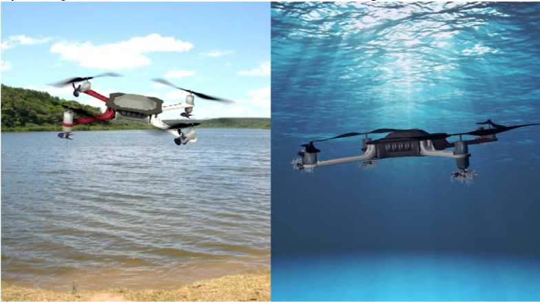
Fig. 23. Simulation of the vehicle HyDrone, our proposed concept of HUAUV for aerial and underwater navigation [11]
The study of Hybrid Unmanned Aerial Underwater Vehicles is an emerging field in Mobile Robotics. In the last decade, the number of contributions to this field has increased significantly, with many proposed concepts and prototypes. Yet, it still has many challenges that need to be addressed, such as media transition control, underwater communication, sensor fusion, and planning strategies. Simulation trials were executed using Matlab language on an Intel CoreTM i7-7500U CPU 2.70 GHz x 4 and 16 GB of RAM under Ubuntu 20.04. Most of them were based on a real-world prototype of the HyDrone (Fig. 24), currently under development on the NAUTEC/FURG, Brazil.
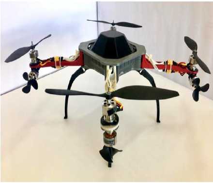
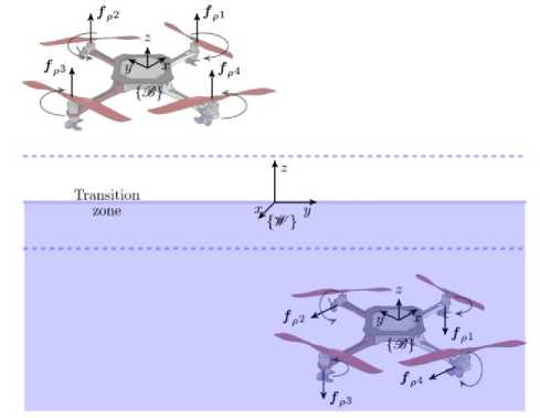
Fig. 24. Hy Drone real-world prototype under development
Fig. 25. Forces and moments generated by the propellers of the vehicle Hy Drone
Figure 25 presents both, aerial and underwater operation modes. In the air, aerial propellers generate forces and moments that make the robot acts like a typical quadcopter UAV, with p and angular movements in к3 occurring in the function of the unbalance in the speed Ω of the rotors. On the other hand, in the water, aquatic propellers operate similarly to a Remotely Operated Vehicle (ROV), with two propellers generating forces fp along the x-axis of the vehicle body, and the other two responsible for providing the thrust along z-axis. Also, between both media, there is a transition zone in which the robot only navigates up or down.
Figure 26 illustrate this expansion process, where the yellow branches are these reference r states, while reds branches are the dynamic models propagate using the correspondent yellow ones [6].
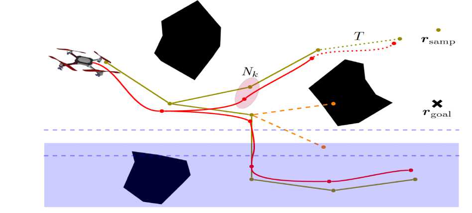
Fig. 26. Tree expansion procedure: each node N in the tree is composed of a reference command (yellow branches) and a propagated state (red branches)
This propagation happens at lines 5, 7 or 10, depending on the conditions of r (t + T ) and rN ( t ). Here, the main idea is to guarantee that, if the reference command propagated in the tree leads to a media transition, then a special action must be taken. This action is randomly chosen between take off or dive beyond the transition zone, as illustrated in Fig. 26.
Thus, addressed the problem of real-time trajectory planning for Hybrid Unmanned Aerial Underwater Vehicles in unknown cluttered environments. To this end, have proposed a variant of the Closed Loop Rapidly-exploring Random Tree approach in which have considered the hybrid dynamics of the system.
Underwater manipulation models
It is natural to wonder: what are the challenges that impede striving the potential of underwater manipulation to a fully autonomous level? Understanding the limitations is key to the prospect of manipulators facilitating the strenuous, or even impossible, human labor in underwater recovery, intervention, and maintenance tasks.
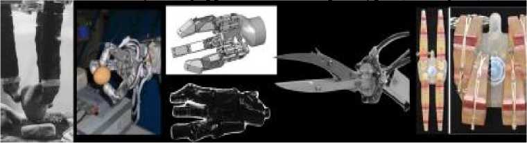
Application-wise, most of the significant advances in the field have been achieved in multi-partnered research projects. Such works include: ALIVE (2001-2004) which was one of the first projects achieving a predefined valve-turning task, TRIDENT (2010-2012) which performed teleoperated manipulation tasks, PANDORA (2011-2015) that aimed at semi-autonomous manipulation, and most recently, OCEAN ONE (ongoing since 2016) which focuses on enhancing the operator experience during manipulation via humanrobot interaction. Examples of the manipulators used in some of these projects [5,12,13] are shown in Fig. 27.
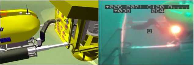
(a) ALIVE [10] (2001-04)
(b) TRIDENT [11], [121(2010-12)
Fig. 27. Examples of underwater robot manipulat
(c) PANDORA [13] (2011-15)
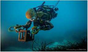
(d) OCEAN ONE [14] (2016-)
In general, I-AUV technology has progressed consider ably since the early 90s, but there is still a long way to go before full autonomy intervention is achieved. Focus on improvements with underwater communication, sensing, data acquisition, and data processing will be the next steps towards increasing levels of autonomy. In the meantime, to overcome these obstacles, state-of-the-art in I-AUVs recovery missions have divided interventions missions into multiple phases. For example, for an object recovery mission, there would be the mapping scene for localization and object detection phases.
For the mapping scene phase, is responsible for surveying the location and collecting images typically using a down-looking camera to achieve photo mosaicking. In another phase, the I-AUV explores the area and identifies objects for recovery. Given the dynamic nature of the underwater environment, multiple-phased missions pose extra challenges. Surveying and identifying a region of interest takes a few hours depending on the area, during which the region may be disturbed by natural occurrences like currents or fauna activities, as well as I-AUV disturbances (if too close to the site). Once deployed for the intervention phase of the mission, the area may have changed slightly. This change can cause a bigger challenge, given that the I-AUV will be returning with processed data to utilize for the mission. Thus, ideally, I-AUVs should be deployed in one single stage where surveillance and intervention are done as part of the same phase. This method can reduce the duration of the mission and the need for more iterations over the area.
Moreover, there are visibility issues. Submerged objects over time become veiled with sand, flora, fauna, rusting and require an increasing degree of intervention to uncover in order to recognize them. Given that object detection and recognition are highly dependent on features like color, texture, contours, and intensity, data collection for computer vision underwater still suffers from image intensity degradation, haze effect, color distortion requiring several pre-processing and post-processing techniques before effectively extracting features.
Up to date, feature extractors like oriented FAST and rotated BRIEF (ORB) have been commonly used. The further study of customized feature extractors can potentiate real-time applicability on object recognition for manipulation purposes.
The collection of delicate deep-sea specimens of biological interest with remotely operated vehicle (ROV) industrial grippers and tools is a long and expensive procedure. Industrial grippers were originally designed for heavy manipulation tasks, while sampling specimens requires dexterity and precision. The grippers and tools commonly used in underwater sampling for scientific purposes, underwater gripping technologies, and identify design trends operated with the possibility of executing typical manipulations of
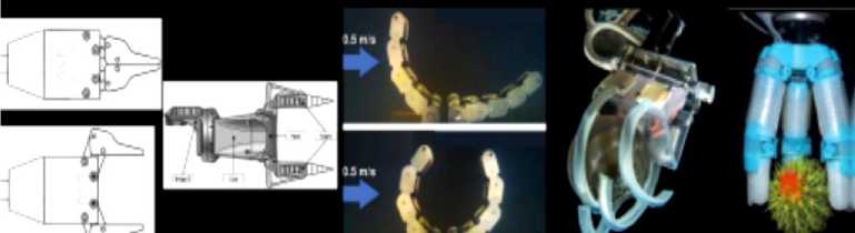
Fig. 28. Grippers and research prototypes [13]
sampling procedures with commonly used grippers and research prototypes (see, Fig. 28
Results indicate that commonly used grippers ensure that the basic actions either of gripping or caging are possible, and their functionality is extended by holding proper tools. Moreover, the approach of the research status seems to have changed its focus in recent years: from the demonstration of the validity of a specific technology (actuation, transmission, sensing) for marine applications, to the solution of specific needs of underwater manipulation.
Unmanned underwater vehicles (UUVs) are generally equipped with one or more manipulators, which allow for interaction with the environment. Presently, marine robotic mobility functionalities are prioritized over object manipulation, with apparently less research done in this field, in comparison to biomimetic locomotion designs and energy provision. Typical tasks are offshore industry operations, archeological campaigns, or sampling specimens to perform biological/geological/ecological analyses. A thorough review of commercially available underwater manipulator is available: although a great number of technological solutions are available, the operation of the manipulator still represents a consistent part of the workload on the pilot. As reported by Galloway et al., most of the commercially available manipulators are designed keeping in mind heavy tasks as pipeline inspection and maintenance. Despite those manipulators not being intended for the collection of delicate structures such as deep-sea biological or archeological samples, the industrial grippers of the manipulators of remotely operated vehicles (ROVs) are nowadays widely employed for scientific sample collection.
The use of UAVs has increased rapidly in recent years. These tools are commonly known as “drones” in daily life and in the literature. The UAV can be defined as a motorized air vehicle that does not carry a human operator on it, can fly by means of a pilot, or autonomously fly by means of microprocessors and sensors on it. UAVs that have autonomous flight capability through predefined programs use aerodynamic forces to takeoff. UAVs can generally show some advantages compared to manned vehicles in terms of their capability to fly in open and closed environments, to be suspended in the air, to ascend and descend to various speed levels, to observe at close distances, and to perform sharp maneuvers. Thanks to these capabilities, they can replace people and perform their tasks successfully, where human intervention is difficult and dangerous. There are many different types of aircraft used today. In general, the mechanisms, configurations, and characteristics of such aircraft may vary. Aircraft can be classified according to their operation, weight, speed, and other characteristics.
Fixed-wing UAVs, similar to migratory birds, fly at close arm length, reduce their drift due to their design, and stand vertically in balance. Fixed-wing UAVs have a great interest in research and development. Fixed-wing UAVs consist of propeller, motor, main body, and wings. While the wings create the lifting force, the propeller is rotated with the help of the motor to produce thrust power for flight and then fixed-wing UAV takes off and starts the flight. Fixed-wing UAVs cannot move backward or perform events such as rotation and hovering. Figure 29(a) shows a model of fixed-wing UAV.
(d)
Fig. 29. UAV types: (a) fixed-wing, (b) rotary-wing, and (c) flapping wing, (d) drone-bird [UAV: unmanned aerial vehicle] [14]
Rotary-wing UAVs are capable of flying by balancing the force generated by the rotors on them. Rotary-wing UAVs continue to be popular in the current UAV market. They have the ability to follow the given trajectory, make vertical landing and takeoff, and hovering. Thanks to these capabilities, revolving-wing UAVs are widely used in aerial robotic research by research centers and universities since they do not need runways or large facilities. Rotary-wing UAVs, which are named according to the number of engines they have, have many varieties, including tricopters, quadcopters, pentacopters, hexacopters, and octacopters. Figure 29(b) shows a model of rotary-wing UAV.
Flapping-wing UAVs are an aircraft inspired by the flapping of birds and insects. Because of the biological structure of insects and birds, flight dynamics are more complex than other UAVs. Most of these types of vehicles are operated manually and perform their forward flights successfully. In addition, it has the potential for a wide range of applications with vertical takeoff and hovering. Flapping-wing UAVs with low power consumption have low load-carrying capacity and low durability. Figure 29(c) shows a model of flapping-wing UAV.
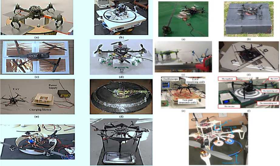
Unmanned aerial vehicle wired charging stations
Wired charging is the process of transferring energy between the UAV and the power source by means of a cable or connector connection. The energy needs of the charging platforms are met through the power lines (copper contacts, connectors, etc.) wrapped in the charging plat-forms in fixed or mobile charging stations. Charging process is carried out by contacting the charging apparatus wrapped in various parts on the UAVs with the charging platforms at the station. Since power lines are connected to fixed positions in the charging platforms, short-circuit problems may occur due to misalignments during landing. To eliminate these problems, charging station has been carried out in different ways. a charging station for autonomous charging of micro-unmanned aerial vehicles (MAVs). The station has been specifically designed for UAVs to perform surveillance flights. The charging stations are located at a fixed point and allow multiple UAVs to be charged at the same time. The charging station is designed to allow the UAVs to land autonomously, charge the battery on the UAV, and resume their duty. The energy is supplied to the station with the power cables at the bottom of the metal plates in the station. The UAVs coming
The batteries are charged with the energy transmitted through the connectors. Three MAVs were used in the system. While any MAV is charging, other MAVs continue the task. The station performed is shown in Fig. 30(a).
(g)
Fig. 30. Wired charging stations for rotary-wing UAVs (a) Mulgaonkar; (b) Cocchioni et al. (c) Song et al. (d) Leahy et al. (e) Valenti, (f) Kemper et al.; (g) Autonomous Quadcopter Charging Station, and (h)
Dynamics-HexHoop Prototype. and (g) Chen et al. UAV: unmanned aerial vehicle
As shown in this figure, the part with the red arm of the UAV must land to the plate covered with a red stripe. There is a risk of short circuit if an incorrect landing occurs.
Cocchioni et al. have realized a study on the charging process of UAVs by collaborating between different devices. By interacting with unmanned ground vehicle (UGV) and UAV, they built a mobile charging station platform that will allow the UAV to charge. A ground control station software was developed to provide coordination and synchronization between UGV and UAV.
During the charging process, fast charging is used instead of a balanced charging. The designed platform is developed as a passive charging mechanism that allows the battery to be charged within 20 min but no full charge. The charger is directly connected to + 12 V DC power. The proposed station is shown in Fig. 30(b) to the charging station are connected to the metal plates in the station by means of metal connectors located at the bottom.
As shown in this figure, charging realizes in the event that the copper plates in the dome-shaped lower region and the connectors on the feet of the UAV come into contact. The fuse is installed to prevent any short-circuit problems in the system. In this study, battery charging is selected instead of battery replacement because of development time, cost, and platform complexity.
Unmanned aerial vehicle battery replacement stations
Charging stations, called battery replacement/swap, are stations for autonomous replacement of the battery on the UAV. Thanks to the mechanical systems in the station, it is detected that the UAV has landed and the position of the battery is determined. After this process, the battery in the station and the battery on the UAV are replaced and the flight mission continues. The process of changing the battery while the UAV is running is called hot swap, and the process of changing the battery while it is stationary is called cold swap. In this type of charging stations, landing operations and mechanical system applications should be done smoothly.
Otherwise, problems may occur during battery replacement procedures. To develop an autonomous system, battery charging should be done automatically. With the charging pads developed for this purpose, UAVs can be charged autonomously with wired or wireless connections. In wired connections, energy is used efficiently, but due to the mechanical contacts in the system affected by environmental conditions, the reliability of the system decreases. In wireless connections, the system is superior in terms of reliability but the efficiency is less. In wireless communication, decrease in energy efficiency can be seen due to the alignment problems of the receiver and transmitter circuit elements. The charging stations for UAVs are different in terms of hardware, technological, mechanical, and usage areas, they have a common purpose. It is to increase the flight times of UAVs by charging or changing batteries autonomously without human touch. In this context, the same process is carried out using different charging station.
Cooperation between Unmanned Aerial Vehicles (UAVs) and Unmanned Ground Vehicles (UGVs)
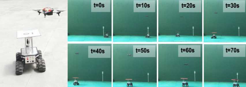
Robot cooperation is key in Search and Rescue (SaR) tasks. Frequently, these tasks take place in complex scenarios affected by different types of disasters, so an aerial viewpoint is useful for autonomous navigation or human tele-operation. In such cases, an Unmanned Aerial Vehicle (UAV) in cooperation with an Unmanned Ground Vehicle (UGV) can provide valuable insight into the area. To carry out its work successfully, such as multi-robot system requires the autonomous takeoff, tracking, and landing of the UAV on the moving UGV. Furthermore, it needs to be robust and capable of life-long operation. In this paper, we present an autonomous system that enables a UAV to take off autonomously from a moving landing platform, locate it using visual cues, follow it, and robustly land on it. The system relies on a finite state machine, which together with a novel re-localization module allows the system to operate robustly for extended periods of time and to recover from potential failed landing maneuvers.
Two approaches for tracking and landing are developed, implemented, and tested. The first variant is based on a novel height-adaptive PID controller that uses the current position of the landing platform as the target. The second one combines this height-adaptive PID controller with a Kalman filter in order to predict the future positions of the platform and provide them as input to the PID controller. This facilitates tracking and, mainly, landing. Both the system as a whole and the re-localization module in particular have been tested extensively in a simulated environment (Gazebo). We also present a qualitative evaluation of the system on the real robotic platforms, demonstrating that our system can also be deployed on real robotic platforms. For the benefit of the community, we make our software open source.
The proposed system in its two versions has been extensively tested on a realistic three-Dimensional (3D) simulated environment (Gazebo) and deployed for qualitative evaluation on real robotic platforms. Figure 31 shows the proposed aerial-ground robot fleet.
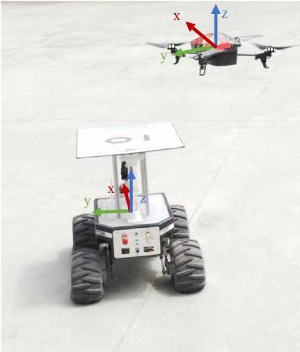
Fig. 31. Cooperation between Unmanned Aerial Vehicles (UAVs) and Unmanned Ground Vehicles (UGVs)
Cooperation can greatly benefit Search and Rescue (SaR) tasks where both long-term operation and a wide aerial view are required. The UAV can travel on top of the UGV (possibly recharging its battery) and, when needed, take off, inspect the area, and land again autonomously.
Two variants for the tracking algorithm were explored. The first one uses the currently estimated 3D position of the landing platform’s centroid relative to the UAV’s body frame as the input cue for a height-adaptive PID controller. The required 3D position is computed by transforming the output of the detectionlocalization algorithm presented to the UAV’s body frame, as detailed in the following subsection. Note that by height-adaptive we refer to the fact that the PID gains are modified continuously depending on the UAV’s flight altitude at every instant. The second variant extends this height-adaptive PID with a Kalman filter to predict the future position of the landing platform. This prediction is then used as the target position for the same height-adaptive PID controller. The implementation of the Kalman filter is based on a work where the prediction was used for tracking pedestrians.
On the real robotic platforms only tested the height-adaptive PID w/o predictive action, since for the predictive system to have worked and would have needed an additional means to localize the landing platform’s position in global coordinates. In the simulated environment, transforming positions to a fixed global frame was straightforward. In the real world, however, this is more complex; implementing a Visual Inertial Odometry (VIO) or even a full visual Simultaneous Localization and Mapping (vSLAM) system would have been required in order to localize the drone in the scene with respect to a fixed frame.
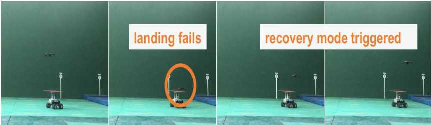
Figure 32, a, b visualizes one of the linear trajectory experiments, and Fig. 32,c shows a sequence of a recovery maneuver [6,11].
(a) (b)
(c)
Fig. 32. Real robotic platforms (a) landing sequence (b) and (c) re-localization maneuver in the real environment
The real experiments were targeted as a qualitative demonstration of how the system can be integrated into real robotic platforms.
A free body diagram method. A free body diagram (FBD) is drawn as in Fig. 33.
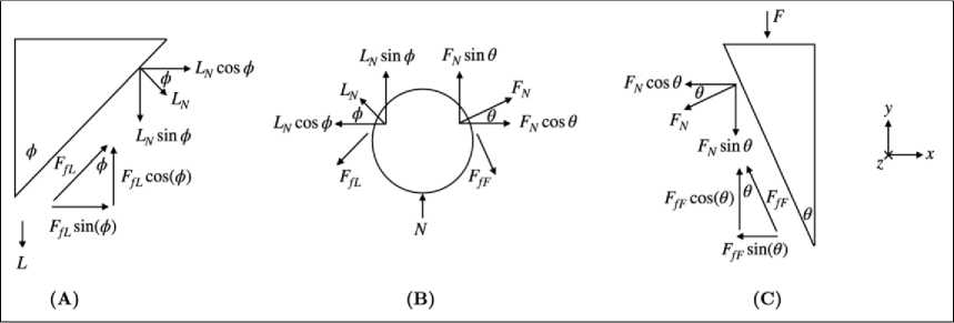
Fig. 33. Quick Connect Free Body Diagram
The FBD is used to solve what servo input force F is required to balance the weight L of a payload. The bearing race’s angle is ф , while the angle of the plunger is 9. The force of friction Ff is a function of the normal force FN or LN and the static coefficient of friction µs between the PLA parts and ball bearings. The normal force acting on the ball bearing in the stepped hole is denoted as N. It is assumed that all forces are evenly distributed across all eight bearings, the system is a static non-deformable body, and the force from the springs in the electrical contacts are negligible. To solve for F in terms of L, the forces in the vertical direction must first be summed using the FBD in Figs 33-A and 33-C. Summing forces from Fig. 33-B in the horizontal direction yields the minimum required input force for the weight of some payload
F = L
( cos ф + ц5 sin ф )( Fs cos 9 - sin 9 ) ( cos 9 + ^ sin 9 )( ^ cos ф - sin ф )
Using this, variables can be substituted for their actual values.
The UAV cannot reliably position itself with millimetre accuracy. However, should the UAV achieve centimetre accuracy, a passive system can align the UAV to achieve millimetre accuracy and allow for the retrieval of a payload using the quick connect system. The passive payload docking station features a broad white background measuring 120 cm x 90 cm to allow for clear detection of ArUco markers. An aluminum extrusion structure holds four 3D printed funnels that allow for inaccuracies of up to 7 cm in the north and east direction and 13_ of yaw. The entire system is fastened to the ground using clear packing tape to limit the effects on the vision system and prevent the system from shifting from rotor wash. A photo of the docking station can be observed in Fig. 34.
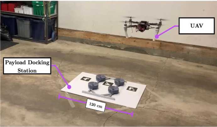
Fig. 34. UAV Payload Docking Station with Approaching UAV
With the UAV system’s layout and quick connect development complete, a novel payload is designed in the following chapter to interface and demonstrate the capabilities of the UAV and its universal payload system (Fig. 35).
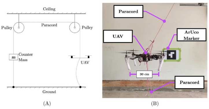
Fig. 35. UAV Tethering System: (A) System Diagram, (B) Tethered UAV During Flight
The UAV system, as observed in Figs 36 and 37, is designed around a 500 mm wheelbase quadrotor MWC X-Mode Alien frame from Afunta.
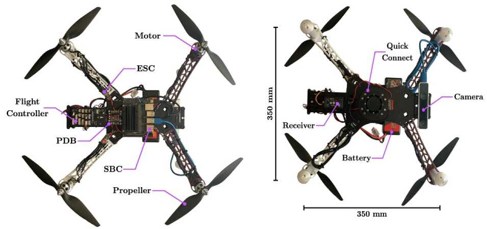
Fig. 37. UAV Bottom View with Labelled
Fig. 36. UAV Top View with Labelled
Components
Components
A quadcopter was selected due to its mechanical simplicity, ability to hover, and maneuverability. The frame selected is optimized for imaging applications minimizing obstructions to the camera and providing ample room for mounting sensors, batteries, and other electronics [11].
Torque Generation
With the selection of the lead screw cap manipulator, a method for applying a torque to the cap had to be considered. Fixing the UAV to the surrounding environment (i.e., a steel gearbox with electromagnets) simplifies the problem in terms of controllability. The problem is simplified because the reaction forces are mechanically constrained, and the focus can be placed on the mechanical apparatus generating the torque rather than designing a controller. Alternatively, the UAV can stay airborne and fix itself to the cap stem’s throat, and a secondary device can be used to introduce torque to the cap. Both methods and any derivatives can produce large torques and are scalable through modifications in mechanical ratios. The constraints with such devices are the many assumptions made of the surrounding environment, leading to limitations in the system’s autonomous capabilities. Additionally, the devices may require multiple actuators and systems, leading to a potentially large and heavy apparatus outside the specifications of the current UAV and quick connect system.
A methodology to counter fixing the UAV to the surrounding environment was to consider a de-sign space that uses the four motors already on the quadrotor UAV. The motors’ use allows for the actuators, or group of actuators, to achieve multiple functions: flight and torque generation.
Although there is a finite amount of torque available, initial estimates projected that the torque would be sufficient for removing or replacing a cap. Additionally, the design space does not limit the autonomous capabilities of the payload. For the concept of removing a cap and introducing a torque with the UAV, it was assumed that the UAV could rigidly fix itself to a cap with the lead screw manipulator.
Fixed-arm multicopters, such as the quadcopter platform, achieve lift by rotating propellers to generate thrust and lift. The direction of rotation of a propeller is opposite to that of its neighbour and is the same as its adjacent counterpart, as depicted in Fig. 38.
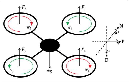
Fig. 38. Free Body Diagram of a Quadcopter While Hovering
The staggering of the propeller’s directions is due to the propeller’s rotation, creating an opposing torque. The staggering of the propeller rotations creates a system that is in a net neutral state in terms of angular momentum.
Therefore, to unbalance the system and maintain level flight, two non-adjacent propellers must spin faster than the other pair of non-adjacent propeller pairs. This difference in the rotation will create a net aerodynamic torque and cause the UAV to rotate in the yaw direction. Using the free body diagram from Fig. 38, clockwise yaw is achieved if F + F > F + F, and counterclockwise yaw is achieved if Fi + F3 < F + F, where Fi is the thrust produced by motor i, and is approximately proportional to the torque generated by a fixed pitch propeller. The relationship is due to the propellers cutting through the air to create thrust and the corresponding opposing torque; the faster the motor spins, the greater the thrust, and the greater the opposing torque. The larger the difference between sets of adjacent propellers, the faster the UAV will yaw, and the greater the torque. However, the system must maintain enough thrust to keep its altitude as 4
^ F; = mg , where Fi remains the thrust produced by some motor i, and mg is the weight of the UAV. i = 1
Additional thrust may be required due to disturbances such as wind; however, in an ideal scenario, a quadcopter will ascend if the summation of forces is greater than the quadcopter’s weight, and it will descend if the summed forces are less than the weight of the quadcopter. Should the cap manipulator provide sufficient gripping strength to hold the UAV without aid from a thrust vector, the maximum ideal torque is achieved when two sets of adjacent motors are operating at 100% while the other pair remains off. Although ideal, only half of the available motors are used to generate a torque as the remaining rotors spin the wrong way and would require reconfiguration to aid in torque generation.
To take advantage of all four actuators, a rotation of the thrust vector was conceptualized. By having the UAV execute a rolling or pitching motion while secured to a cap by a moment arm, the UAV can exhibit a torque to the cap. For example, rolling the UAV will transition the vertical thrust vector to include a horizontal component at an angle _ a s pictured in Fig. 39.
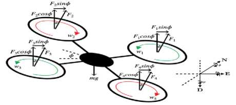
Fig. 39. Quadcopter Executing Positive Roll ф for a Counterclockwise Torque
The maximum counterclockwise torque occurs when ф is equal to 900; however, the UAV should still maintain a vertical thrust vector to sustain flight and minimize the load on the moment arm.
The minimal lifting force required is established ^ F max/ cos ( ф ) = mg , where Fmaxi is the maximum i = 1
thrust produced by motor i, ф is the roll angle, and mg is the weight of the UAV when there is no acceleration.
Collaboration with Ground Vehicles
The MAGMaS fully autonomous operation mode is targeted for when the system evolves in a well-structured fully known environment [12]. It relies on two key components: a trajectory planner and finite state machine (FSM); which together com-pose the task planner. The Tele-MAGMaS is composed by 3 main robotic parts, i) the LBR-iiwa arm, ii) the OTHex aerial manipulator and iii) the Omega.6 haptic interface, commanded by a centralized controller, which is interfaced with a simulator/visualizer. The high-level control of the full system is realized in Matlab-Simulink, linked to the hardware via GenoM3 components (OTHex, Joypad, MoCap, LBR-iiwa) or Matlab S-function drivers (Haptic device, V-REP), which are C++ function natively interacting with Matlab. The Tele-MAGMaS first experiments were showcased at the Hanover Fair 2017, as part of the finals of the KUKA 2017 Innovation Award, see Fig. 40.
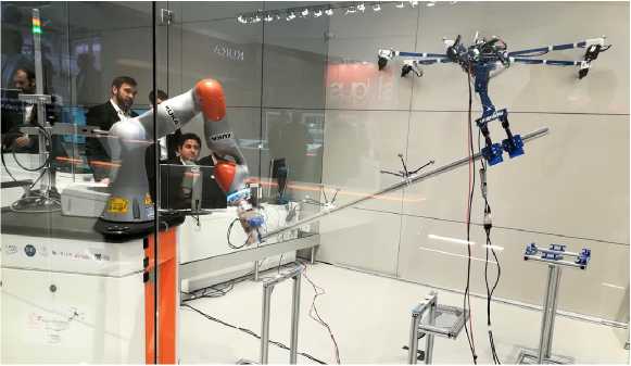
Fig. 40. A snapshot of the cooperative manipulation state of Tele-MAGMaS using bilateral teleoperation approach performed during the KUKA 2017 Innovation Award at the Hanover Fair
The demonstration presented the main features of the Tele-MAGMaS system and a proof-of-concept application. During the fair week, the demonstration was running every hour (or more), thus demonstrating the high reliability of the proposed system and control architecture.
The experiment sequence is depicted in Fig. 41 and consists in the following: at first the OTHex is manually flown to grasp the bar from one of its ends, while the ground robot autonomously grasps the other end.
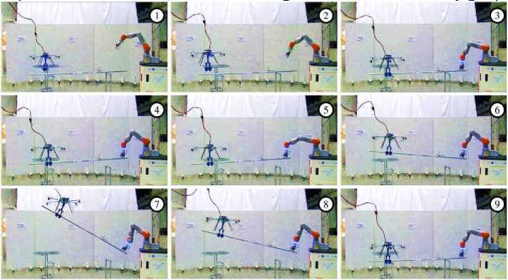
Fig. 41. Time-lapse of a MAGMaS cooperative manipulation task
Both robots are at their initial position (1), approach to the bar (2), grasping the bar (3), cooperative lifting (4), cooperative lateral motion (5), cooperative lifting up to 30◦ (6-7-8) and release of the bar (9). See attached multimedia for the corresponding video of the experiment. Once both manipulators are attached to the bar the co-manipulation is fully autonomous: they lift the bar from its supports, move it twice along a line in the horizontal plane (blue part) and then synchronously lift the bar up to 30◦ (green part). Then they bring the bar back to its starting position.
This new category of systems leverages the advantages of both mobile ground manipulators and aerial manipulators, in order to perform tasks which would be impossible for homogeneous systems. A scenario of object manipulation (pose tracking), out of the working conditions that a single robot could achieve, is enabled through the tele-operation of the MAGMaS.
The originality of the MAGMaS approach is to consider a heterogeneous multi-robot system composed of both ground and aerial manipulators, see Fig. 42, to leverage their individual flaws.
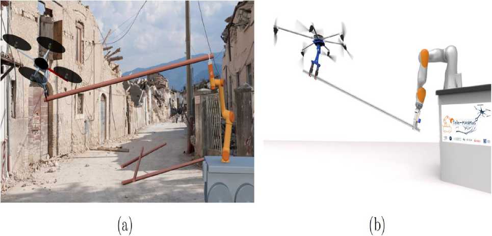
Fig. 42. Potential use cases for MAGMaS of different composition. Left (a) in a USAR scenario with a mobile base and an underactuated AR cooperatively cleaning buildings remains. Right (b) in a decommissioning scenario with a fixed ground robot and a multi-directional thrust AR cooperatively manipulating a pipe
The small payload of the AR is compensated by the strength of the ground manipulator, while the limited workspace and small torque at the EE of the ground manipulator is balanced by the virtually unlimited workspace and the favorable lever provided by AR. Thanks to their large workspace AR can exert force on the load in order to reduce the torque induced at the EE of the ground manipulator by the load weight. With this teaming, AR can act as flying companions helping the ground manipulator to carry long loads by grasping them on another extremity and mitigating torque at the ground manipulator EE while it carries the object, thus allowing manipulation of the load in a cooperative way.
In disaster area such as place which have radioactive leakage or fire accident, there is a need to make a robot which can collect information inside the place while ensuring the safety of the operator. Taking the example, wheeled robots which can be operated manually and move inside Fukushima nuclear power plant have been proposed. Wheeled type robot has a high payload and preferred in many exploring robot’s movements design. However, at disaster site, the environment severe many obstacle that scatter everywhere, even on the middle of the stairs. This condition made wheeled type robot become more difficult to move. To overcome this condition, the use of flying type robot have many advantages, one of them is to open the way when encounter a blocked path. proposed a new method for door opening mission by using aerial robot. Our proposed for flying manipulator is using four rotors as the main actuator for flying and lightweight manipulator using pneumatic actuator. On previous report, opening door mission by perching to the door, push the door using force generated by rotating propeller, and turning door knob using lightweight Access-operation Decoupled Drive-Arm (ADD-Arm) had been reported [12].
Figure 43 shows the overall structure of the aerial manipulator. Total weight is 1700 gr with ADD-Arm mounted on the right side and two micro pumps on the opposite side as counter weight for balancing. It used Ardupilot2.6 as a main controller, standard 2.4 GHz transceiver and 2200 mAh battery with flight time around 5 minutes. Two micro pumps were used for adsorption purpose and for power actuation.
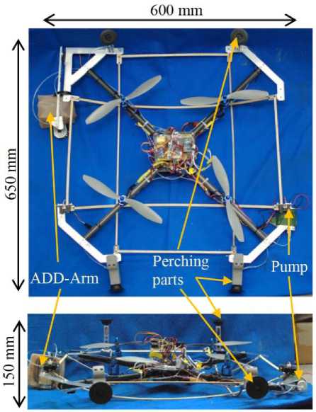
Fig. 43. Overall Structure of Aerial Manipulator
The Process of door opening can be seen in Fig. 44.
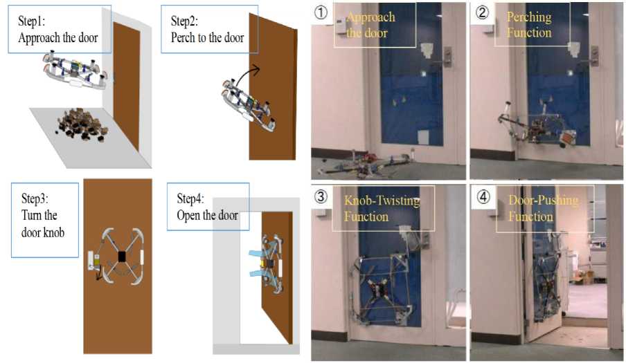
(a)
(b)
Fig. 44. Demonstration of Door-Opening Operation (a) Robot Mission; (b) Implementation of Door Opening Mission [13]
First the robot approaches the door location and locate the door knob position. Second it then perches to the door by sticking the front suction pad and perform attitude changing function until robot orientation parallel with door plane. Third the robot moves the manipulator to the knob position and twist it. Final step, it then pushes the door using force generated by the propeller. The demonstration picture of door-pushing operation is shown in Fig. 44, a.
Сетевое научное издание «Системный анализ в науке и образовании» Выпуск № 3, 2022 год of the door. Second, it then performed perching function to the door by increasing the speed of rear rotor so that it performed pitching motion until parallel with door plane and properly attached with fixed support parts. Third, it then used ADD-Arm to perform door knob-twisting function with help of suction pad and variable restriction mechanism. Last, by rotating all the rotor, it then generated lift force and the force transferred to push the door. It was shown that it was possible to do door opening mission with performing time around 3 minutes.
There are many examples of bio-inspired designs, from a power-controlled jumping robot with agility and power close to that of a galago (the animal with the highest vertical jumping ability), to a biomimetic robotic platform for studying bat flight specialization, and a biorobotic sticky disk for underwater hitchhikers inspired by sucker remoras.
Vehicles capable of acting both in the air and under the water offer a large number of applications in a variety of scenarios, some of them extreme, ranging from the extreme cold of polar regions to the hot and humid climate of rain forests. Operating and transiting between air and water in such challenging environments are difficult tasks, with many setbacks to achieve a good perception and actuation overall. Most of these Hybrid Unmanned Aerial Underwater Vehicles (HUAUVs) were inspired by aerial vehicles, such as quadcopters and hexacopters [3]. These derivations benefit the motion control in the air and underwater, generally eliminating the need for changes in their mechanics and geometry characteristics. On the other hand, the problem is that a design based on aerial vehicles tends to present a considerably better performance in the air than in the water medium. The opposite is also true for those based on underwater vehicles.
Underwater manipulators can be equipped with various types of grippers on the end-effector. The commercial ones come with different interchangeable grippers each of which has their own specific purpose. A common gripper type is one with parallel acting jaws which includes a slot for a standard T-bar handle (ISO 13628–8, 2002), and its primary function is grasping different objects and tools in a variety of subsea operations. Tooling is generally designed with a T-bar exactly for this purpose. Different grippers include three/four finger intermeshing jaws, two/three finger floating jaws, scissor jaws, suction foots, etc. Gripper actuators are usually hydraulic and the gripping force of commercially available grippers ranges from 35 kgf to 652 kgf.
Depending on the nature of the task for which they are designed, underwater manipulators come with different number of degrees of freedom (DOF). Both commercial and experimental underwater manipulators are usually designed with three to six DOFs without taking gripper's mobility into account. The reason for this is that three DOFs are sufficient for achieving an arbitrary position and six DOFs for both arbitrary position and orientation of the end-effector (tool) in the workspace. The term “n-function” is often used in the literature to describe the number of actuators contained in a manipulator and this term includes the gripper's mobility as well, so for example a seven function manipulator means that there are six actuators responsible for manipulator motion that provide six true DOFs plus one actuator for gripper (jaw) mobility. Underwater manipulators with seven or more DOFs (without gripper mobility) are not very common, but they do exist. True seven DOF manipulators are said to be inherently redundant from the kinematic point of view. This feature can play an important role in the automation of manipulators since the redundancy can be exploited for a secondary objective such as obstacle avoidance.
Any robotics application of underwater manipulators requires applying kinematics modeling planning and control algorithms. Underwater manipulators generally have serial-chain mechanical structure similar to industrial robot arms. There is much literature about robot kinematics that can be applied to underwater manipulators.
Gripper structures
In the early 90's a few authors proposed and experimented on sea-water driven actuators for subsea manipulators. Some of the benefits of water hydraulics are low viscosity, high power density, non-flammable properties and zero environmental impact. However, this actuation approach was abandoned over the years due to its various disadvantages such as corrosive and abrasive properties, lubrication and sealing issues, unsuitable working temperature range, etc. Today all the existing commercially available underwater manipulators and most of the experimental/prototype underwater manipulators developed for research purposes run on either oil hydraulic or electric power, both of which have their advantages and disadvantages. Denket
(2006) proposed a hybrid power structure using both hydraulic and electric actuators for a single manipulator in order to have the benefit of both (Fig. 45).
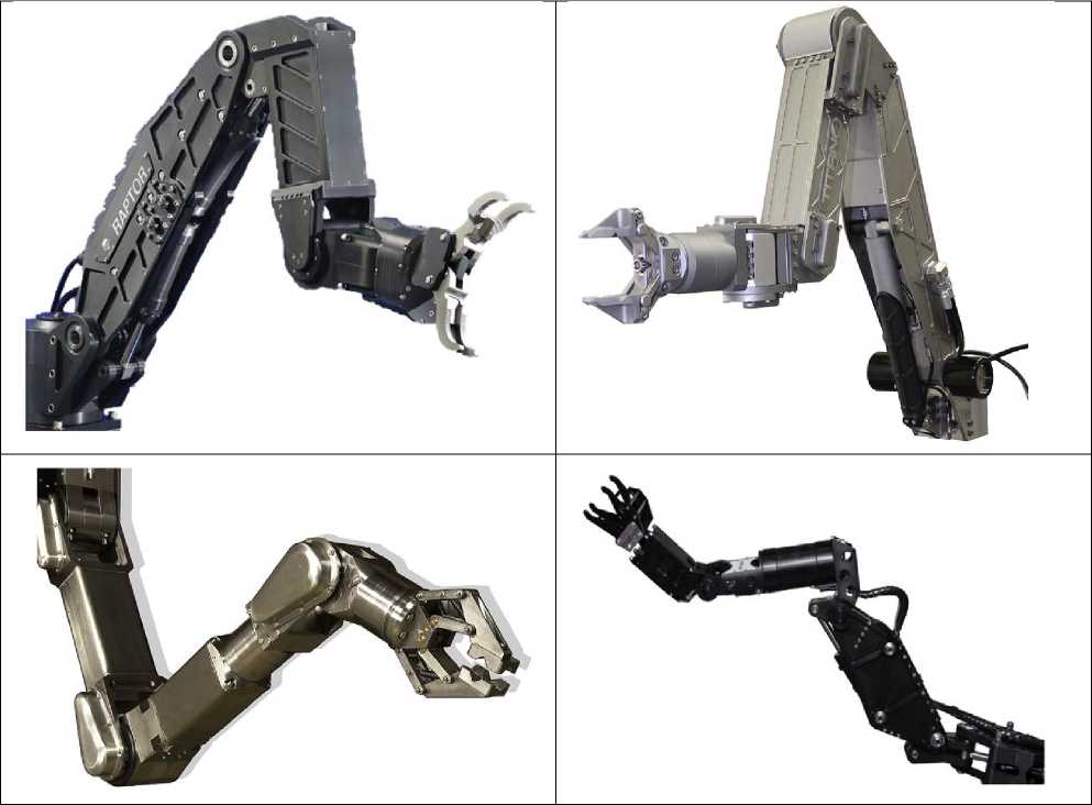
Fig. 45. Gripper structures [5, 14]
However, this actuation method has not yet found use in the commercial sector. Biodegradable fluids have begun to be introduced to minimize the impact on the environment of fluid leaks.
It is necessary to use the three manipulators together to grasp a large object almost the size of the base of the manipulator mount. Together the manipulators are controlled to behave like a broad three-fingered gripper. The object should overlap with all three manipulator regions in order to get a firm grasp, and the object's center of mass should be near to the intersecting point of each manipulator area. The base orientation of each manipulator (yaw angle) is set such that it points outward from the middle of the UAV, creating a triangular grasp to create force closure, equivalent to a three-finger gripper spaced equidistantly. Without considering the gripper, the above grasping posture determines the location of the manipulator tip.
Robotic arms are the most relevant branch of the interaction mechanisms for an aerial manipulation system. Configurations of robotics arms differ by degrees of freedom ranging from 1-DOF to 2-DOF and several DOFs [15-20].
Sample configurations are presented in Figs. 46 and 47.
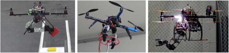
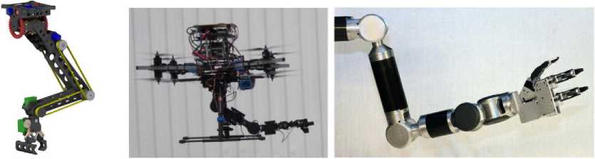
Fig. 46. Robotic arm configurations, (a-b) 2-DOF, (c) 6-DOF, (d) 5-DOF, (e-f) 7-DOF
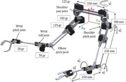
Fig. 47. 10-DOF lightweight dual-arm manipulator
However, depending on the combined angle, the gripper may be configured to maintained either to be open or close, as seen in Fig. 48.
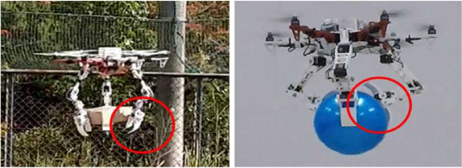
Fig. 48. Two approaches of grasping a large object using all three manipulators in unison. The gripper is kept open or closed based on the relative distance between the UAV and the object while grasping
To grasp smaller objects that are closer to the UAV frame, an open gripper configuration is appropriate. Using the passive compliance joint, a closed gripper configuration adjusts to the rough surface of the objects, in which case a greater force is applied to the object by pulling the tip further towards the object. The dis- tance sensors at the manipulator tip and the directional load input from the actuators of the manipulator are used during the autonomous grasping process to determine whether the object is grasped.
Numerous grasping tests are conducted to assess the different grasping capabilities of the developed UAV system. Similar to landing tests with rope support, initial experiments are performed indoors. Followed by tests for object transportation outdoors.
Figure 49 displays the grasping of some objects using the manipulator grippers.
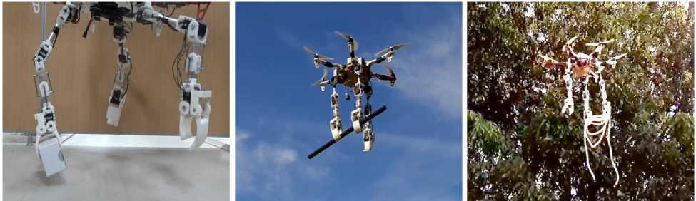
Fig. 49. Grasping objects using the manipulator's gripper. (From left to right) Grasping a small cuboid object using single gripper, a long pipe using two grippers and a bundle of rope being carried between two grippers
A small cuboid shape with a diameter of 50mm x 70mm x 200mm is seen in Fig. 49(left) picked by one of the grippers. Between the grippers, the shorter side of the object (50mm) is grasped. Two of the grippers of the manipulator are seen in Fig. 49(center and right) holding a long bar item and a bundle of rope respectively. An experiment to illustrate the ability to grasp is carried out indoors using all three manipulators in unison. As for the object, a large cylindrical object, about 250mm in diameter and about 100mm in height, was selected. The sequential process is seen from left to right in Fig. 50 during the grasping experiment.
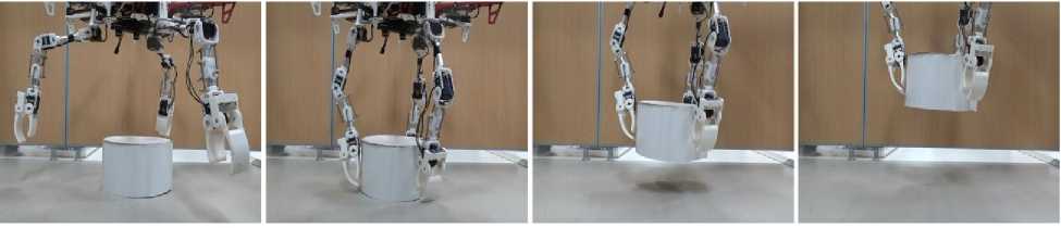
Fig. 50. Experimental process of grasping a large object of diameter about 250mm [20]
For easier positioning control during the experiment phase, the UAV is fixed using rope support (not seen in the figure). The UAV is limited to a height such that the object can be autonomously grasped by the manipulators. The UAV is raised away from the scene after the target is securely grasped.
Another experiment is conducted where the UAV must remain close to the barrier (or a vertical surface). The purpose of this experiment is to conduct a horizontal pushing motion towards an object. One of the manipulators is used to contact the vertical surface, similarly to the preceding experiment. This time, the attitude of the UAV is adjusted so that it travels towards the obstacle after impact with the object while keeping the position of the manipulator steady. The manipulator serves as a spacer between the obstacle and the UAV at this time, so that the UAV body and the propellers do not touch the obstacle. The process for the experiment is seen sequentially from left to right in Fig. 51.
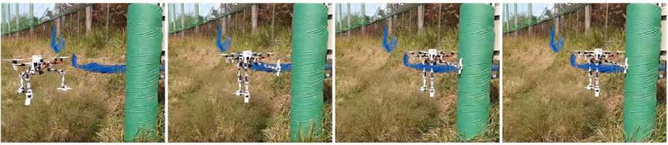
Fig. 51. Making physical contact with a vertical surface using the manipulator and pushing in the direction of the obstacle using the UAV attitude control
To directly maneuver the UAV through a very narrow tunnel like structure, an experiment was conducted. The tunnel was built by inserting two wide parallel wooden planks with a gap of around 1m. The purpose of the experiment was to measure the motion of the UAV during the manipulator's interaction with an obstacle. The UAV was then manually navigated through the tunnel, with the manipulators extended on either ends. The flight series is as shown in the Fig. 52.
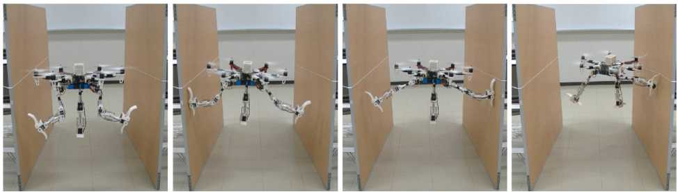
Fig. 52. Navigating the UAV through a very narrow tunnel resulting in a crash [20]
It should be noticed that, directly after entering the tunnel, the UAV moved left, but the left-hand manipulator avoided the obstacle. The UAV then went right, and it was again guarded by the right manipulator. But then, while still preserving its position on the right, the UAV shifted forward. During this time, because of friction, the right-side manipulator, still being in contact with the wall, acted as an anchor point and swung the drone right, resulting in a crash on the tunnel wall.
Rubik’s Cube manipulation
Benchmarks for robot manipulation are crucial to measuring progress in the field, yet there are few benchmarks that demonstrate critical manipulation skills, possess standardized metrics, and can be attempted by a wide array of robot platforms. To address a lack of such benchmarks, we propose Rubik’s cube manipulation as a benchmark to measure simultaneous performance of precise manipulation and sequential manipulation. The sub-structure of the Rubik’s cube demands precise positioning of the robot’s end effectors, while its highly reconfigurable nature enables tasks that require the robot to manage pose uncertainty throughout long sequences of actions. We present a protocol for quantitatively measuring both the accuracy and speed of Rubik’s cube manipulation. This protocol can be attempted by any general-purpose manipulator, and only requires a standard 3x3 Rubik’s cube and a flat surface upon which the Rubik’s cube initially rests (e.g. a table). In [21] was demonstrated this protocol for two distinct baseline approaches on a PR2 robot. The first baseline provides a fundamental approach for pose-based Rubik’s cube manipulation. The second baseline demonstrates the benchmark’s ability to quantify improved performance by the system, particularly that resulting from the integration of pre-touch sensing. To demonstrate the benchmark’s applicability to other robot platforms and algorithmic approaches, presented the functional blocks required to enable the HERB. While all of the benchmarks demonstrate critical aspects of robot manipulation, none of them strenuously measure the robot’s ability to simultaneously perform precise manipulation and sequential manipulation. We therefore propose a Rubik’s Cube manipulation benchmark that requires the robot to perform long sequences of highly precise manipulations, as illustrated by Fig. 53.
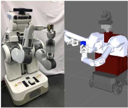
Fig. 53. Rubik’s cube manipulation can be used to benchmark robot manipulation across a wide array of algorithmic approaches and robot platforms, such as the PR2 and HERB [21]
The precision required to manipulate the Rubik’s cube is a product of its own structure. Each of its six faces consists of nine sub-cubes arranged into three rows and three columns. The state of the cube can be altered by rotating one of the rows (columns) around an axis parallel to the columns (rows).
However, given a row (column) to rotate, both of the other rows (columns) of the face must be held in place. Since each sub-cube has a dimension of only 1.9 cm , each rotation requires the robot to position its end-effectors with sub-centimeter accuracy. Achieving this level of manipulation accuracy is difficult in the presence of uncertainty in the Rubik’s cube’s pose with respect to the end-effectors. Uncertainty will exist to varying degrees for all general-purpose robots, and can stem from the inability to perfectly calibrate high degree of freedom arms, imperfect actuators, and a number of other sources.
As shown in Fig. 54, insufficiently precise manipulation can cause under-constrained portions of the cube to be unintentionally rotated, or prevent intended rotations of over-constrained portions of the cube from being executed.
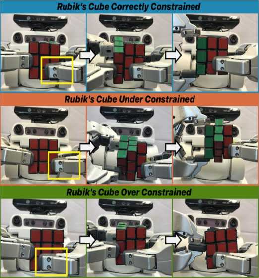
Fig. 54. The robot must precisely position its grippers to rotate the left column of the Rubik’s cube while constraining the middle and right columns in place
[Top Row: The robot correctly positions its grippers: it is constraining the two right columns of the cube. The yellow box highlights the position of the constraining gripper. Middle Row: The robot only touches one column of the Rubik’s cube and therefore fails to constrain its middle column. Bottom Row: The right
Сетевое научное издание «Системный анализ в науке и образовании» Выпуск № 3, 2022 год gripper is touching all three columns of the cube; this prevents the left gripper from rotating the left column of the cube.]
The finite state machine is modified such that each re-grasp of the Rubik’s cube is achieved through a push grasp. Specifically, given a Rubik’s cube face to grasp, the HERB robot’s gripper approaches perpendicularly to the face. The robot’s middle finger is positioned such that once it has made contact with the face, the robot’s gripper has reached a pre-grasp amenable to rotating the face, as shown in Fig. 55.
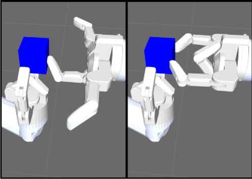
Fig. 55. HERB’s simulated Barrett hands manipulate the Rubik’s cube in blue
[Left: The right gripper uses a push-grasp to make contact with the Rubik’s cube. Upon making contact, the right gripper reaches the desired pre-grasp. Right: The right gripper closes its outer fingers to transition from pre-grasp to grasp.]
The dead reckoning baseline completed Rubiks-1-20 in 463.45 seconds, and it was unable to complete any of the higher single trial tiers. This result indicates that the system has sufficient accuracy to solve a Rubik’s cube given multiple attempts.
The simulated robot is indeed capable of performing all of the trajectories prescribed by the state machine, demonstrating the generalizability of the benchmark beyond the provided baselines.
To increase the payload carrying capacity, many strategies are proposed based on the actuators and evaluation criteria. Some of the early quadruped robots adopted hydraulic actuators due to the high power-to-weight ratio. However, the bulky auxiliary devices in hydraulic system result in the large self-weight of the robot. Therefore, the payload to weight ratio (payload capacity, PLC) and energy efficiency of hydraulic quadruped robots are relatively low. The criterion for energy efficiency, cost of transport (CoT), of Boston Dynamics hydraulic BigDog is 15, which is significantly higher than those of humans or animals of similar scale. Electrically-actuated quadruped robots are developed to make up these shortcomings. By integrating electric motors with the passive dynamics and elastic elements, energy is stored by kinetic or elastic components, and quadruped robot efficiency is improved. CoT ( P = mgv ) metric draws more interests in the highspeed dynamic locomotion, such as jumping, running, back-flipping, etc, while the external payload is not taken into account.
As for the payload capacity (PLC), the existing quadruped robots is usually lower than 1:1 under normal walking speed according to the available reports. For example, walking test on a commercially 12 kg quadruped robot Unitree A1 shows that 10 kg payload is achievable with a speed of 0.1 m/s. 30 kg SpotMini is able to carry 14 kg payload. 50 kg ANYmal can carry 10 kg payload. Baby elephant, electrical-hydraulically actuated with parallel legs, has payload of 100 kg with the PLC of 0.77. PLC of some representative quadruped robots under 150 kg are listed in Fig. 56.
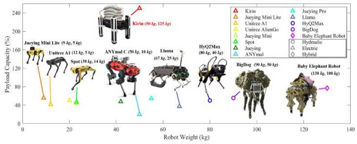
Fig. 56. The overview of PLC, which is the ratio of payload to weight
The reported quadruped robots [22] with varied self-weight below 140 rmkg are listed based on the available information. The first and second value with each robot are the self-weight and the payload weight respectively. At the current stage, the experiment result for Kirin’s maximum payload is 125 kg. Therefore, PLC of Kirin is 250 %. Hydraulic, electric and hybrid actuators are labelled as circle, triangle and diamond respectively. Among the quadruped robots above, HyQ2Max and Big Dog are hydraulically. The quadruped robots below 80 kg are all electrically actuated.
During the Tunnel and Urban Circuits, CERBERUS' core robots were the “ANYbotics ANYmal B” quadruped, and two classes of “Aerial Scouts”, namely multirotors with conventional airframes, as well as the \Gagarin" class of collision-tolerant aerial robots. We have further added a roving robot called “Armadillo”. ANYmal has the most extended endurance compared to all our robots and integrates our multi-modal perception and autonomy solutions. At the same time, ANYmal can also deploy wireless communication nodes. The Aerial Scout, with conventional airframe, is a traditional quadrotor design and acts as a rapid explorer. The Gagarin collision-tolerant Aerial Scout is of smaller size and its mechanical structure enables it to survive contact with surfaces and to make its way through challenging, narrow, multi-branched, and possibly multi-level underground environments. Both aerial platforms integrate the CERBERUS multimodal perception and autonomy pipelines and operate without any human supervision after take-off. Lastly, the Armadillo roving platform primarily deploys a high-gain wireless communications antenna deeper in the underground environment, while maintaining an optical fiber connection to the Base Station. As a fallback role, this roving robot also integrates multi-modal perception capabilities to allow it to detect artifacts.
Figure 57 presents the CERBERUS robots deployed at the Tunnel and Urban Circuits of the SubT Challenge [23].
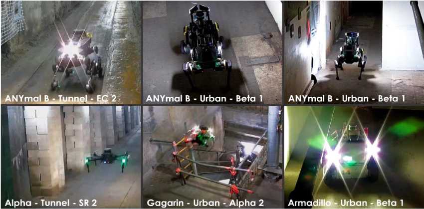
Fig. 57. Instances of deployments of the CERBERUS robotic system-of-systems in the DARPA Subterranean Challenge Tunnel and Urban Circuits. Upper row: ANYmal B on wheels and two standard ANYmal B robots exploring sections of the Tunnel Circuit's “Experimental” Course and Urban Circuit's “Alpha” and “Beta” Courses. Lower row: the Alpha and Gagarin Aerial Scouts in the Tunnel Circuit's “Safety Re- search”Course and the Urban Circuit's “Alpha” Course respectively, alongside the Armadillo rover in the Urban Circuit's “Beta” Course. [Relevant video results are available at ]
To enable perception in low-light environments, all three M100 Aerial Scouts are equipped with Cree LEDs, which are synchronized with their visible light camera's shutter producing a power-efficient flashing behavior (see, Fig. 58).
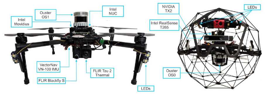
Fig. 58. The Charlie (left) and Gagarin (right) Aerial Scouts
Three robots, named Alpha, Bravo, and Charlie, utilize the DJI Matrice 100 quadrotor as their airframe. For high-level processing, including sensor data collection, localization, mapping, and planning, an Intel NUC Core-i7 computer (NUC7i7BNH) is mounted on each robot, while an Intel Movidius Neural Compute Stick is used for artifact detection. Charlie further integrates thermal vision and thus provides unique localization capabilities in visually-degraded environments, as well as thermal object detection (e.g., for the survivor artifact class).
Conclusions
An aerial manipulator is a robotic system (see. Fig. 59), which has the capacity to fly and at the same time to manipulate objects in its environment by applying reasonable forces and torques [24].
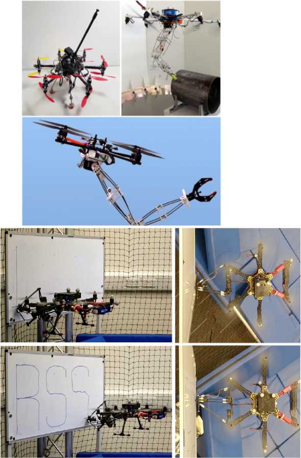
Fig. 59. Types of aerial manipulators and technology operations
Most commonly they consist of a flying robot and at least one manipulator arm. In such robots, the great workspace and the agility of aerial robots meet with the dexterity of conventional manipulators. This system breaks ground to many different robotic applications, e.g., pick and place, aerial physical interaction, and aerial grasping. Although aerial manipulators open new doors for various robotic tasks, their control and motion planning is not trivial, since they are an interconnection of multiple nonlinear robotic systems. For this reason, it is important to analyze their system dynamics and develop control algorithms dealing not only with the problem of tracking the outputs we are interested in, but also with the internal dynamics of the system and how they are coupled with each other (Fig. 60).
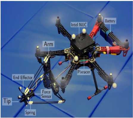
(a)
Fig. 60. The aerial manipulation platform used in the ‘aerial writing’ experiments with its individual components labelled (a); Reference and actual tip position (left) as estimated by Vicon. Blue corresponds to contact segments while orange refers to free flight. Visual error (right) between reference and actual tip position. Similarly, as in the RSS experiment, maximum error does not exceed 1 cm (b); Reference tracking error of the tip position (top), MAV (middle) and measured contact force (bottom). The tracking accuracy of the end effector is significantly greater than that of the MAV, given that they remain in the [-10,10] mm and [-50,50] mm ranges, respectively (c)
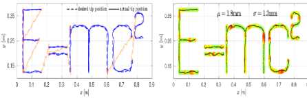
(b)
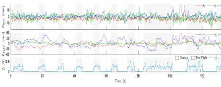
(c)
Most commonly they consist of a flying robot and at least one manipulator arm. In such robots, the great workspace and the agility of aerial robots meet with the dexterity of conventional manipulators. This system breaks ground to many different robotic applications, e.g., pick and place, aerial physical interaction, and aerial grasping. Although aerial manipulators open new doors for various robotic tasks, their control and motion planning is not trivial, since they are an interconnection of multiple nonlinear robotic systems. For this reason, it is important to analyze their system dynamics and develop control algorithms dealing not only with the problem of tracking the outputs we are interested in, but also with the internal dynamics of the system and how they are coupled with each other.
The complexity of biological systems makes them difficult to replicate artificially, but meeting the demands of two modes of locomotion in a single robotic system has been done. Bioinspired robots have been presented that can both fly and move on land, either by jumping or by walking [25,26]. Other robots take cues from amphibious locomotion in nature and can move on land and in water. The compromise necessary to locomote effectively in air and water makes it impossible to define a strategy that is optimal. However, based on the analysis we are able to make several proposals for robotic AquaMAVs, the implementation of which is ongoing. Such vehicles offer very unique functionality and are already sought after in industry and research. The problem of hybridizing aerial and aquatic locomotion has not been well addressed by conventional robot design, but a wealth of successful design principles are used by animals to move in both air and water. By examining and abstracting key biological design principles we will be able to create a new robotic operating paradigm of operation in air and water.
References Unmanned aerial vehicles. Pt. 1: bio-inspired and aerial-aquatic locomotion
- Ducard G.J.J., Allenspach M. Review of designs and flight control techniques of hybrid and convertible VTOL UAVs. Aerospace Science and Technology. 2021. Vol. 118. Pp. 107035.
- Tvaryanas A.P., Thompson W.T., Constable S.H. The U.S. Military Unmanned Aerial Vehicle (UAV) Experience: Evidence-Based Human Systems Integration Lessons Learned. In Strategies to Maintain Combat Readiness during Extended Deployments. A Human Systems Approach (pp. 5-1 5-24). 2005. Meeting Proceedings RTO-MP-HFM-124, Neuilly-sur-Seine, France: RTO. [Available from: http:.www.rto.nato.int/abstracts.asp.]
- Siddall R, Ortega A.A, Kovac M. Wind and water tunnel testing of a morphing aquatic micro air vehi-cle. Interface Focus. 2017. Vol. 7. Pp. 20160085. http:.dx.doi.org/10.1098/rsfs.2016.0085. Launch-ing the AquaMAV: bioinspired design for aerial–aquatic robotic platforms. Bioinspir. Biomim. 2014. Vol. 9. Pp. 031001 (15pp). DOI:10.1088/1748-3182/9/3/031001.
- Moore J. Closed-Loop Control of a Delta-Wing Unmanned Aerial-Aquatic Vehicle. arXiv:1906.01532v1 [cs.RO] . 4 Jun 2019.
- Aldhaheri S. et al. Underwater Robot Manipulation: Advances, Challenges and Prospective Ventures. arXiv:2201.02954v1 [cs.RO]. 9 Jan 2022.
- Pinheiro P.M. et al. Trajectory Planning for Hybrid Unmanned Aerial Underwater Vehicles with Smooth Media Transition. arXiv:2112.13819v1 [cs.RO] 27 Dec 2021.
- Suming Q., Weicheng C. An Overview on Aquatic Unmanned Aerial Vehicles. Ann Rev Resear. 2019. Vol. 5, No 3. Pp. 555663. DOI: 10.19080/ARR.2019.05.555663
- Ma Z. et al. Configuration Design and Trans-Media Control Status of the Hybrid Aerial Underwater Vehicles. Appl. Sci. 2022. Vol. 12. Pp. 765. https://doi.org/10.3390/app12020765.
- Maia M.M. et al. Demonstration of an Aerial and Submersible Vehicle Capable of Flight and Underwa-ter Navigation with Seamless Air Water Transition. arXiv:1507.01932 [cs.RO]. 2015.
- Rockenbauer F.M. et al. Dipper: A Dynamically Transitioning Aerial-Aquatic Unmanned Vehicle. Robotics: Science and Systems 2021. Held Virtually, July 12-16, 2021.
- Debruyn D. et al. MEDUSA: a Multi-Environment Dual-robot for Underwater Sample Acquisition. IEEE Robotics and Automation Letters (RAL) paper presented at the 2020 IEEE/RSJ International Con-ference on Intelligent Robots and Systems (IROS) October 25-29, 2020, Las Vegas, NV, USA (Virtual).
- Staub N. et al. The Tele-MAGMaS: An Aerial-Ground Co-manipulator System. IEEE Robotics and Automation Magazine. 2018. Vol. 25, No 4. Pp.66-75. DOI: 10.1109/MRA.2018.2871344. hal-01935127
- Daimetry A. AERIAL MANIPULATOR WITH DOOR OPENING FUNCTION. Proceedings of the 9th JFPS International Symposium on Fluid Power, Matsue, 2014 Oct. 28 - 31, 2014. Pp. 195-200.
- Sivčev S. et al. Underwater manipulators: A review. Ocean Engineering. 2018. Vol. 163. Pp. 431–450.
- Jing X., Xiao S. Configuration Design and Trans-Media Control Status of the Hybrid Aerial Underwater Vehicles. Appl. Sci. 2022. Vol. 12. Pp. 765. https://doi.org/10.3390/app12020765.
- Ucgun H. et al. A review on applications of rotary-wing unmanned aerial vehicle charging stations. Intern. J. of Advanced Robotic Systems. 2021. No 1. Pp. 20. DOI: 10.1177/17298814211015863.
- Paul H. Development of a Versatile Three-arm Aerial Manipulator System. Doctoral Thesis. Doctoral Program in Advanced Mechanical Engineering and Robotics Graduate School of Science and Engineer-ing Ritsumeikan University. March 2021.
- Ollero A. et. al. Past, Present and Future of Aerial Robotic Manipulators.IEEE TRANSACTIONS ON ROBOTICS. 2022. Vol. 38, No. 1. Pp. 626-645. Preprint version final version at http://ieeexplore.ieee.org/. 2021
- Yılmaz E. Modeling and Nonlinear Adaptive Control of an Aerial Manipulation System. Submitted to the Graduate School of Engineering and Natural Sciences in partial fulfillment of the requirements for the degree of Master of Science Sabanci University, July, 2019.
- Paul H. et al. TAMS: development of a multipurpose three-arm aerial manipulator system. Advanced Robotics. 2021. Vol. 35. No 1. Pp. 31-47. DOI: 10.1080/01691864.2020.1845237.
- Yang B. et al. Benchmarking Robot Manipulation with the Rubik’s Cube. arXiv:2202.07074v1 [cs.RO] 14 Feb 2022.
- Zhou Y. et al. Kirin: A Quadruped Robot with High Payload Carrying Capability. arXiv:2202.08620v1 [cs.RO] 17 Feb 2022.
- Tranzatto M. et al. CERBERUS: Autonomous Legged and Aerial Robotic Exploration in the Tunnel and Urban Circuits of the DARPA Subterranean Challenge. arXiv:2201.07067v1 [cs.RO] 18 Jan 2022.
- Tzoumanikas D, еt al. Aerial Manipulation Using Hybrid Force and Position NMPC Applied to Aerial Writing. Robotics: Science and Systems 2020 Corvalis, Oregon, USA, July12-16, 2020.
- Brunner M. et al. Energy Tank-Based Policies for Robust Aerial Physical Interaction with Moving Objects. arXiv:2202.06755v1 [cs.RO] 14 Feb 2022.
- Fishman J. et al. Dynamic Grasping with a “Soft” Drone: From Theory to Practice. arXiv:2103.06465v1 [cs.RO] 11 Mar 2021.
