User's Profile Replication Tree and On Demand Replica Update in Wireless Communication

Author: Prem Nath, Chiranjeev Kumar
Journal: International Journal of Computer Network and Information Security(IJCNIS) @ijcnis
Article in issue: 3 vol.5, 2013.
Free access
Replication strategy is mostly useful for replicating the called mobile user's profile at selected locations where some caller mobile users have higher calling rate. It plays important role in personal communication services (PCS) in order to reduce call setup cost and call setup time. In prior replication schemes, replicated sites (visitor location registers) have no inter relationship. We have proposed a novel and innovative replication tree which is buildup from replicated VLRs (visitor location registers). VLRs are replicated based on effective replication probability of caller mobile user. Home location register (HLR) keeps update replica at root VLR in the replication tree and root VLR forwards update replica to a VLR in the replication tree on demand. The main objective of the proposed scheme is to reduce call setup time and call setup cost by enabling replication of called mobile user's location profile at certain visitor location registers (VLRs) where caller mobile user roams. We have presented analytical modeling which shows that setting inter-relationship among the replicated sites helps in further reducing the call setup cost.
Location Management, Replication Tree, User's Profile Replication, Effective Replication Probability
Short address: https://sciup.org/15011175
IDR: 15011175
Text of the scientific article User's Profile Replication Tree and On Demand Replica Update in Wireless Communication
To facilitate the tracking of mobile nodes, PCS network is partitioned into many registration areas (RAs) and each RA may include tens or hundreds of cells, also known as paging area (PA). A cell is a basic unit of area served by a base transceiver station (BTS). The base stations of a RA are connected via wire lines to a service switching point (SSP) [1]. Each RA is serviced by a VLR which is associated with mobile switching center (MSC). An HLR is associated with tens or hundreds of VLRs. Mobile nodes communicate through wireless link via base transceiver station (BTS). All the BTSs belonging to a paging area (PA) are wired-connected to a mobile switching center (MSC). It has been observed that, even the communication areas are very large and there are hundreds of cells, the set of communication areas from which calls are made to a mobile node is relatively static and confined. For example, a study on e-mail traffic patterns indicates that about eighty percent of mails are from three most frequently calling communication sites [2]. So, if we place called user’s location profile (replica) at these three sites, we can reduce the search cost and call setup cost significantly. These results also suggested that by using replication scheme, a significant call latency and network cost can be eliminated.
In personal communication services (PCS), services to the mobile users are provided irrespective of their location and movement. In order to set up a call, a mobile user should be tracked and located. Keeping the location updated of a mobile user in a PCS networks is expensive because many signal flows and database queries are needed to achieve the task [3, 4, 5, 6, 7]. A well-known basic and simple scheme is two-tier HLR/VLR (home location register / visitor location register) scheme to update the location of mobile users using HLR (home location register) and VLR (visitor location register). The two-tier HLR/VLR location management scheme is used in Interim Standard 41 (IS-41), Global System for Mobile Communications (GSM) and also adopted by Internet Engineering Task Force (IETF) in mobile IP. When mobile user A calls user B, the lookup algorithm must initiate a remote query (lookup) to the HLR of B, which may be at a remote site. Since performing remote queries can be slow due to high network latency, therefore current PCS systems usually improve the lookup to HLR by maintaining location profile of called user B at current VLR of caller A. There are several enhancements of basic two-tier schemes like per mobile node based location profile caching/replication [6, 8, 9, 10, 11], forwarding pointer schemes [12, 13, 14], and hybrid scheme [15]. But there is no interrelationship among the replicated sites proposed in the prior schemes. Most of schemes rely on deferred update of replica and hold “loose” form of replica most of the time which is not useful in call setup. Immediate update of replica is necessary whenever called mobile user changes its location. For example, in hybrid scheme [15], replicas are updated only when forward chain of VLRs is reset (threshold reached). There is possibility that called mobile user changes its location before chain is reset in caller mobile user’s network. In this situation, “loose” replica might be there in caller VLR and call setup request will be failed. Caller VLR has to get call setup information from HLR of called mobile node which results in more call setup cost and more call setup time.
Replicating user’s location profile can reduce lookup time significantly, since the location of the called user is more likely to be obtained by a single query on the local database (VLR) rather than a high latency remote query to HLR of called user. However, the associated cost of replication is the update cost incurred in maintaining consistent replicas every time a mobile user moves in the foreign network. In traditional distributed databases, replica consistency is maintained by using distributed locking protocols, which can be very expensive. Every time a user moves, the user's HLR must initiate updates to all the replicas of the user's profile which results in extra cost. It is more for those users who have high mobility rate. Hence, the larger the number of replicas, the more work performed by the HLR to keep update the replicated VLRs. Another approached is the deferred update of the replicas. But in this approach, the replicated sites (VLRs) have “loose” form of replica which could result in miss tracking of called mobile user and consequently results in more call setup cost. We have proposed a tree which is formed over replicated VLRs. Threshold has been imposed on the number of replicated VLRs in order to limit the network activity and work performed by the user's home database.
In next generation of wireless communication networks, a series of new technologies have been developed to facilitate the high-quality broadband services to mobile users (MUs). Examples of these technologies are: IMT-2000, UMTS, GPRS, EDGE, CDMA-2000, W-CDMA, HSPA, and LTE. Although there are some new functional entities introduced in these new technologies but the basic notion for location management has not changed significantly. One of the changes is the smaller registration areas (RAs). In LTE systems, where smaller cells deployment is expected, MU with high mobility will be able to access different wireless networks frequently. It will increase traffic overhead. This signaling includes not only location update signaling but also security association signaling [19, 20]. So, home agents/HLR could be signaling traffic bottleneck for such future mobile networks with high-mobility users. Since the smaller size cells deployment and reduction of registration area (RA) size can improve the system performance in terms of packet loss and MU localization, but it may also degrade the performance in terms of signaling traffic load due to frequent change in location induced by smaller RAs. Therefore, some mobility databases must be designed to store at caller MUs location that can be retrieved for the future service delivery.
We have proposed a replication tree scheme. The replicated sites (VLRs) are interlinked in tree notion to localize location update of caller mobile user. The HLR updates the location profile of called mobile user at root VLR. We have analyzed the different situation as per CMR values of caller and caller mobile users in the following section and according update of replica and location update of caller have been proposed. But whenever updated replica of called mobile user is not present in the root VLR, HLR should be queried to find out the exact location of called user. We use expression “mobile node” and “mobile user” interchangeable in this paper. The rest of this paper is organized as follows. Section 2 contains the location management procedure involved in hybrid scheme [15]. Section 3 elaborates the proposed scheme. Section 4 contains the analytical modeling and performance evaluation of proposed scheme and hybrid scheme. Section 5 contains the numerical results illustration and performance discussion. Section 6 ends with conclusion and future study.
-
II. Related work
Hybrid scheme [15] applies forwarding pointer and user’s profile replication strategies together and maintains optimal number of chain length ( η ) and replicas (k) in order to minimize overall location management cost. When caller mobile user has high call rate (CMR is high), more number of replicas are beneficial in reducing the lookup time of the location of the called mobile user. Otherwise when caller mobile user has high mobility rate (CMR is low), using forwarding pointer technique is beneficial in minimizing the frequent home registration.
The location update under hybrid strategy [15] proceeds as follows. Whenever there is location registration request by a mobile user, the threshold ( η ) value of forwarding chain length is checked. If threshold ( η ) is reached, η is reset and a new chain of VLRs is started and location replica of called mobile node is replicated at k numbers of VLRs. Location of caller mobile node is updated to HLR. Otherwise mobile node registers to the new MSC/VLR ( mobile switching Center / visitor location register ) and new MSC/VLR links with old MSC/VLR in the forwarding chain. The threshold η is incremented by one. The old MSC/VLR sends the profile of mobile node to the new MSC/VLR and acknowledgement is exchanged. The threshold ‘ η ’ and ‘k’ are selected based on value of CMR.
The call setup in hybrid scheme [15] takes place as follows:
-
1. The calling user sends a call setup request to its current serving MSC/VLR
-
2. The current MSC/VLR checks if it has a location replica of the called mobile node. If a replica is found, the caller’s VLR sends a routing message directly to reach the first VLR in the forwarding pointer chain. Otherwise,
through BTS (Base Transceiver Station) .
-
(a) The HLR of called mobile node is contacted which sends a routing request
message to the first MSC/VLR of the called mobile node in the forwarding pointer chain.
-
(b) The query message propagates to thecurrent MSC/VLR of called mobile node following the MSCs/VLRs in chain one by one.
-
(c) The current MSC/VLR sends routing information to the calling MSC/VLR (if it is a replica hit) or HLR (if it is a replica miss). In case of replica miss, HLR stores and forwards the routing information to the calling MSC/VLR.
-
3. Now, the calling MSC/VLR sets up a call connection to the called mobile node via the SS7 signaling network.
-
III. The Proposed REPLICATION tREE
We have observed that in most of the prior schemes, specially proposed in [6, 10, 11, 12, 13, 14, 15, 16] CMR plays big role in selecting a particular location management scheme. If CMR value of called mobile user is higher, forwarding pointer schemes are selected otherwise replication schemes are selected. But we have proposed a replication tree scheme which can be used in both conditions; either CMR is low or high. We have considered the number of calls to a mobile user made by a caller mobile user and total number of calls made by caller in certain time period (T) to define the effective replication probability ( ρ erp ). Effective replication probability shows that how much probability of a VLR has to keep location profile replication of a called mobile user. The number of replication (k) to different VLRs is decided based on the ρ erp .
Algorithm 1: Calculation-Effective Replication
Probability ( ρ erp )
Suppose a mobile node MN i is currently under VLR m and a correspondent node CN j is under VLR n . There are mtc m,n number of calls from CN j to MN i in time period T. Following steps are adapted while deciding the location profile replication of MN i :
-
1. HLR accesses the total mobile node’s working profile of CN j in time T and it decides the effective replication probability ( ρ erp ) of VLR n as follows:
Ретр^
mtcmn EU mtcn,t Where,
-
(a) mtcm , nis the number of calls made by CN j (VLR n ) to mobile user MN i (VLR m ) and
-
(b) 2 t=o mt cn , t is the total number of calls
made by CN j in time T.
If VLR n has higher effective replication probability, location profile of MN i is replicated at VLR n .
The proposed replication tree model has been shown in Fig. 1. The location profile of a mobile user is replicated at k number of VLRs by the HLR based on effective replication probability. A replication tree is constructed from the replicated VLRs (Algorithm 2). This replication tree is adjusted dynamically. Replication is done only when the cost of accessing a HLR is more than the accessing cost of user’s profile by VLRs in the tree.
-
A. Creation of Replication Tree
Suppose there are k VLRs namely VLR 1 , VLR 2 , VLR 3 , …, VLR k which have been visited by caller in foreign network and where called mobile user’s location profile is to be replicated. Suppose these VLRs are visited by caller in the sequence given above and effective replication probabilities of these VLRs are ρ erp,1 , ρ erp,2 , ρ erp,3 , …, ρ erp,k respectively. The proposed replication tree is dynamically adjusted when threshold (k) is reached. As shown in Fig. 1, there are k VLRs where mobile user’s location profile has been replicated. The root VLR 1 maintains a table which contains all the VLRs under it and the location of mobile user. The information stored in this table is used for forwarding the location of mobile node.
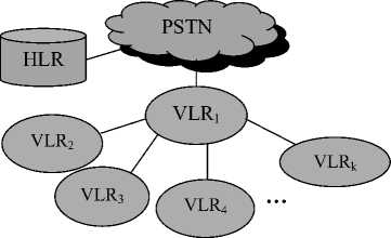
Fig. 1 Proposed Replication Tree Model
Algorithm 2: Create-Replication-Tree
-
1. Make the first visited visitor location register VLR 1 as root of the replication tree and initialize the counter, i = 1.
-
2. Repeat until i ≤ k
-
(a) If caller enters a new VLR, suppose VLR i , make this VLR as child of root VLR and
-
(b) i = i+1
-
3. If the counter ‘i’ reached the threshold ‘k’, then remove the old VLR and place the new VLR of caller in the tree.
-
B. Location Update in Proposed Scheme
Whenever there is change in the location of caller mobile node, it registers to new MSC/VLR. The new MSC/VLR informs the root VLR. The location update of caller mobile node is carried out as shown in Fig. 2.
Location Update Procedure:
-
1. The mobile node sends a location update (RQ-LU) message to the serving BTS.
-
2. The serving BTS sends location update message (RQ-LU) to new MSC/VLR.
-
3. The new MSC/VLR informs (INFO-LU) to root VLR. The root VLR updates its database and sends acknowledgement along with copy of location replica of called caller.
-
4. The new VLR sends location deregistration message to old VLR.
-
5. If new VLR is not in the tree, the root VLR sends location update message to the HLR and updates the threshold value (k). If threshold is reached, old VLR is replaced by new VLR and replication is made to new VLR.
-
C. Call Setup in Proposed Scheme
The call setup time is dependent on copy of the location profile of called mobile user stored at current VLR of caller mobile user. If current VLR does not store the replica, root VLR is queried. If root VLR does not contain the updated copy of the replica, HLR is queried and current location of called mobile is obtained. The call setup is carried out as per following algorithm:
Algorithm 3: Call-Setup
-
1. The caller mobile user sends a call request message to its MSC/VLR through current BTS.
-
2. If the serving MSC/VLR stores a location replica of called node, it contacts the called node’s serving MSC/VLR directly and gets the routing information. Otherwise
-
(a) The current MSC/VLR sends a location request message to its root VLR.
-
(b) If root VLR stores called mobile node’s location profile, it forwards to the caller MSC/VLR. Otherwise,
-
(c) The caller MSC/VLR sends a location request message to the HLR of called mobile node.
-
(i) HLR transmits a location request message to the current serving MSC/VLR of the called mobile node.
-
(ii) The MSC/VLR of called mobile node locates the called mobile node and assigns a temporary location directory number (TLDN) for it and sends the TLDN to the HLR.
-
(iii) The HLR updates its database and forwards the TLDN to the calling MSC/VLR.
-
3. A connection is established from the calling MSC/VLR to the called MSC/VLR by using the received TLDN.
-
D. Update of Location profile of Called Mobile User
It is very important to update the location replica of a mobile node whenever mobile node changes its location. We analyzed the conditions (i) and (ii) and we found that reducing the location update cost and replica update cost are necessary to reduce the overall cost of location management.
It is due to frequent change in the location of both the users. Analyzing the condition (iii) we have observed that location update frequency of both the users is low and therefore overall cost is not as much as cost incurred in conditions (i) and (ii). As we have discussed the proposed location update procedure in section III that mobile user updates its location to the root VLR. So, keeping the update replica at root VLR is beneficial and root VLR can forward this to new VLR at time of acknowledgement to location registration. The root VLR also monitors the presence of mobile user in a VLR. So, if mobile user stays in a VLR for longer period and root VLR gets replica update from HLR in that period then root VLR sends this update replica to the current VLR of caller.
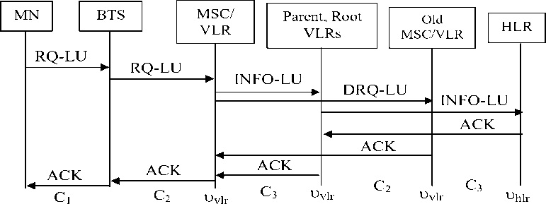
Fig. 2 Location Update Procedure
-
IV. ANALYTICAL MODELING AND PERFORMANCE ANALYSIS
We have presented analytical modeling and performance analysis in this section for both the schemes, proposed and hybrid [15]. The variables/references and their values used [5, 10] are given in Table 1.
We assume that the mobility rate of MN is λm and residence time in a subnet is Gamma distributed with mean 1⁄ and the call arrival rate λc is a Poisson process.
λ
The residence time of a MN is a random variable with general density function (t) and the Laplace transformation:
А ∗ ( S )
=∫ (t)e stdt
■)t=o
Table 1: Variables/References Used
|
Variable/ Reference |
Description |
Value Used |
|
C 1 |
Cost of message transfer between mobile node and BTS |
0.1 |
|
C 2 |
Cost of message transfer between BTS and MCS/VLR |
1 |
|
C 3 |
Cost of message transfer between two VLRs |
5 |
|
C 4 |
Cost of message transfer between VLR and HLR |
25 |
|
υ vlr |
Cost of updating/accessing location database by a VLR |
0.1 |
|
υ hlr |
Cost of updating/accessing user profile database by HLR |
0.2 |
|
k |
Number of VLRs to be replicated |
Varies |
|
η |
Number of VLRs in the chain (Threshold value) in Hybrid scheme |
Varies |
The Laplace transform of a Gamma distribution is as follows:
A ∗ ( s )=( γµ ) γ (3)
+ γµ
Therefore, Д∗(λ )=( γλ ) , the residence time is λ γλ exponentially distributed and for γ = 1,
λ
Cost of Location Update:
Suppose caller mobile user and called mobile user cross ‘i’ and ‘j’ number of subnets (VLRs) between two consecutive calls. The probability of crossing ‘i’ number of subnets between two consecutive calls as expressed in (7) is ρ m . . The cost of location update π L in proposed scheme is calculated as follows:
f'∗( λ )= λ + λ = 1+ CMR
Where call-to-mobility ratio CMR = λ λ
Now we define the probability ρ p of one or more incoming call between two subnets (VLRs) crossings and the probability ρ m of crossing ‘i’ number of subnets between two consecutive calls as suggested in [5, 7, 17, 18] as follows:
1. Cost of Location Update:
π
ρ (2 Cl +2C2 +4C3+5 υ ■Jr )
=∑і ρ [ +(1- ρ ) +5 υ )
i=0 ×(2 Ci +2 C2 +4 C3 +6 υ7lr +2 c. + υUr )
ρ
ρ
λ . _ CMR
λ + λ 1+ CMR
= λ + λ ( λ + λ )= ρ p (1+CMR) (6)
where i=0, 1, 2, 3…
We assume that k and N are the VLRs under the
+∑ϳ ρ ×(2 C, + υ „ )
Suppose =2 +2 +4 +5 υ , so we have
π =∑і ρ [ ρ inX +(1- ρ ) ]
×(2 + υ?lr + υ + )]
proposed tree where location profile of a mobile user has been replicated and total number of VLRs in the foreign network respectively. We define the probability ( ρ in ) that next movement of MN is under the same proposed tree in terms of k and N as follows:
к -1
ρ = (7)
It is discussed earlier that the proposed replication tree system is useful when the cost of accessing the HLR is less than the cost of cost of accessing the root VLR and updating ‘k’ VLRs in the proposed tree. Other constraints like bandwidth, processing load on root VLR should be also taken into consideration. We assume that root VLR
has enough storage and processing capacity. So, subject to the bandwidth constraint, the value of threshold (k) imposed on number of VLRs in the proposed tree can be calculated as follows:
3 C4 +2 υ Ur + C3 к ≤
Сз + υ ■Jr
+∑ϳ ρ (2 C, + υ „)
7=0
= ∑і ρ +(2C4 + υ7lT + υUr )∑і ρ (1- ρ )
1=0 ^ 1 = 0
+∑ϳ ρ (2C4 + υ „)
7 = 0
GO
= ∑і ρ p(1+ CMR ) +(2 C. + υ ,lr + υUr )
co
×∑іρ . (1+ CMR )(1- ρ )
CO j
+∑ϳρ . (1+ CMR ) (2 C. + υUr )
j=0
(2 C4 + υ 71Г + υ llr )(1- ρ ) 2 C4 + υ Ur
= + +
2 Ci+2c2 +4C3+5 υ7lr
A. Location Management Cost in Proposed Scheme
Location management in proposed scheme has been discussed in section 3. It includes location update cost of caller mobile user, replica update cost, and call setup cost as discussed in section 3.
CMR
(2 C4 + υ 7lT + υ llr )(1- ρ ) 2C4 + υil;
+ +
2 Cl +2 c2 +4 c3 +4 c4 +6 υ7lr +2 υUr
CMR
(2 C4 + υ 71Г + υ llr ) ρ
-
CMR
The call setup cost π C is calculated as follows: nc = 2^ + 2C2 + 2C3 + 3 u „ ir (10)
And the total cost π T is calculated using (10) and (11) as follows:
П = 2C i + 2C 2 + 2C 3 + 3 U i r
(2C 4 + u „, r + UM r ) p in
—
+
CMR
2 C i + 2C2 + 4 C+ + 4 C 4 + 6 и i r + 2 и ^
CMR
-
B. Location Management Cost in Hybrid Scheme [15]
The location update cost of hybrid scheme has been discussed in section II. It includes the costs of location update of caller mobile user in forwarding pointer manner, replicating called mobile user’s location profile at k VLRs if threshold reached, and call setup. Suppose caller mobile node is presently under jth VLR (j=1, 2, 3, …, η ) in the hierarchy and it crosses ‘i’ number of subnets (VLRs) between two consecutive calls. So, caller mobile node will update ^—J times and ( i — [~]) times to HLR and previous VLR respectively. Therefore, the location update cost π L/Hybrid as suggested in [15] is calculated as follows:
n L/Ну bri d
Z r I i + 71 ( 2 C i + 2 C 2 + 2 C 3 +
'• [| y 1 { 2( к +1)C 4 + (к + 4) и ,r + ( к + 2) и ,r i = 0
-
+ (i — F+Ф (2Q + 2C 2 + 2C 3 + 3 U ir )]
=У p - [I T 1 {2(к+1)C 4 +(к+ r + ■+r }
+ i(2C i + 2C 2 + 2C 3 + 3 uvi r )]
2 C i + 2C 2 + 2C 3 + 3 и i r
}
CMR
+
У p ^ | ( 2»+1 ) C 4 + »+1 )
+ (k + ^)uh ir )
Ulr
i=o
Let i = n y + m, where n=0, 1, 2, 3, ...« and 0 < m < y. Then ^— J = ^ ^^Ш J and 0 < (m + j) < 2 y. We have considered the values of ‘m’ and ‘j’ together which is greater than zero and less than 2 n . So, [—J = ^ n y +m+’ J = n + 1, if (m+j) is considered maximum and (12) and (6) are expressed as:
2 Ci + 2C2 + 2C3 + 3 и ir nL/Ну br i d =
CMR
у у ( n + 1)
+ y p™ y x{2(к + 1)C4+ (к + 1)^r+ (к + 2)uMr} n=0
i \ny(i \ pm pp (i+сMR/ \i+СMR/
Therefore, we have
2 Ci + 2C2 + 2C3 + 3 и ir nL/Ну Гт i d =
CMR
+pP {2(к + 1) C4+ (к + 1)u„ir+ (к + 2)uM r} co x У(п + 1) (---1---) У (---1)
yv v (1 + CMR) y (1 + CMR)
n=0m=0
2 C i + 2C 2 + 2C 3 + 3 и i r
CMR
+pP {2(к + 1) C4+ (к + 1)uvlr+ (к + 2)uMr} x f ( 1 f [(1 + CMR)n — 11
y(n+ )( 1 + cMR) I (1 + CMR) n I n=0 L J
(1 + CMR\
X ( CMR )
Let X = (-----) , so we have
\U-CMR/
2 Ci + 2C2 + 2C3 + 3 и ir nL/Hybrid = CMR
+{2(к + 1)C4+ (к + 1)u i r+ (к + 2)Ui r} хУ(п+ 1)(Xn —Xn + i)
n=0
2 C i + 2C 2 + 2C 3 + 3 и i r
CMR
+{2(к + 1)C 4 + ( к + 1) u v ir + ( к + 2) u }Q _ ^ + x) 2Ci + 2C2 + 2C3 + 3 u vir
CMR
+{2( к + 1)C 4 + ( к + V)u i r + (к + 2) U ir } x (--------1--------+-----1-----} (13)
I (1 + CMR) t — 1 (1 + CMR) T v J
The call setup cost consists of cost of message from current VLR of caller to the current VLR of called mobile node (if replica found) or cost of message to HLR to find out the current location of called mobile node (if replica miss). In both cases (replica hit or miss), current VLR of called mobile node is approached through chain of VLRs. We assume that average chain length ( η /2) is accessed to setup a call. So, the call setup cost π C/Hybrid as suggested in [15] is calculated as follows:
n c/Hybrid = p n { 2C i + 2C 2 + u ir + ^(2C 3 + 2 u ir )}
+ (1 — pi n ){
2C i + 2C 2 + 2C 4 + u M r + Ц , ir + 2x П (2C 3 + 2 u i r )
I
= P n {2C i + 2C 2 + yC 3 + ( y+ 1) u I r }
+ (1 - p n ){2C i + 2C 2 + 2C 4 + u M r + 2 yC 3 + (2 y
+ 1) u I r }
The total π T/Hybrid for a call setup in hybrid scheme using (13) and (14) is as follows:
2 C i + 2C 2 + 2C 3 + 3 и i r
П Г /Ну b ri d =
CMR
+ P n {2C i + 2C 2 + yC 3 + ( y+ 1) u I r }
+ n J2C i + 2C 2 + 2C 4 + u Mr)
+ (1 P n ){ +2 y C з + (2 y +1) u i r }
+{2( к + 1)C4+ (к + 1)uvir+ (к + 2) Uir} x|. + 1 .1
I (1 + CMR) у — 1 (1 + CMR) T
-
V. RESULTS AND OBSERVATIONS
The total cost comparison of the proposed scheme and the hybrid scheme have been shown in Fig. 4, Fig.5, Fig. 6, Fig. 7, Fig. 8, and Fig. 9. Referring to Fig.4, the threshold values ‘k’ and ‘ η ’ are fixed at 4 and the value of CMR varies from 1 to 100. Probability ρ in is considered 0.5. The total cost in the proposed and hybrid schemes are reducing as CMR is increasing. But total cost in proposed scheme is higher than hybrid scheme for CMR ≤ 2 (mobility is higher). It is due to high percentage of replications (k=4) made and consequently their update cost. Generally when MN has higher mobility rate (CMR is low), frequency of location update is high therefore having less number of replications is beneficial. The total cost in hybrid scheme is less than the proposed scheme for CMR =1 because more number of VLRs in forwarding pointer is used to reduce home registration by enabling local registration to the previous VLR and has very low percentage of replication. The main objective of the proposed scheme is to reduce call setup cost and time by replicating the location profile of the called mobile node when calling rate is high (high CMR).
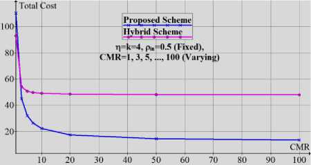
Fig. 4 Total Cost Comparison Varying CMR
In Fig. 5, the value of CMR is fixed at 1 for both the schemes. The threshold values ‘k’ (in proposed scheme only) and ‘ η ' are equal and varying from 1 to 50. The total number of VLRs (N) in foreign network has been considered 50. It has been observed from the illustration shown in Fig. 5 that upto threshold 7, total cost in hybrid scheme is decreasing. But for higher threshold ( η ≥7), total cost in hybrid scheme is increasing. The total cost in proposed scheme is less than hybrid scheme for threshold ≤ 5 and threshold ≥12. When mobility rate of caller mobile user is higher, less number of replication is beneficial and having more number of replications results in more cost (hybrid scheme) as it is obvious from illustration shown in Fig. 5. The total cost in proposed scheme is decreasing with increase in threshold.
In Fig. 6, the value of CMR is fixed at 1 for both the schemes. The threshold value ‘η' for forwarding pointer is fixed at 4 and number of replication ‘k’ is varying from 1 to 50. The total number of VLRs (N) in foreign network has been considered 50. It has been observed from the illustration shown in Fig. 6 that total cost in hybrid scheme is increasing with number of replications. But the total cost is decreasing in proposed scheme as ‘k’ is increasing. The total cost in proposed scheme is higher for 1 ≤ k ≤ 7. So, providing more number of VLRs under replication tree, proposed scheme performs better than hybrid scheme. It has been observed from the illustration shown in Fig. 6 that proposed scheme performs better when CMR is low by having more number of VLRs in the proposed tree.
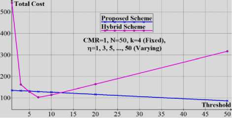
Fig. 5 Total Cost Comparison Varying Threshold
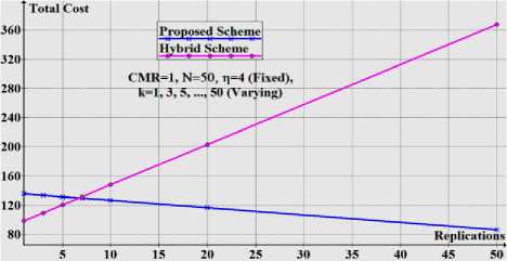
Fig. 6 Total Cost Comparison Varying Replications
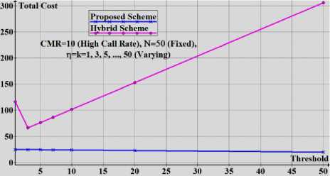
Fig. 7 Total Cost Comparison Varying Threshold
Fig. 7, the value of CMR is fixed at 10 for both the schemes. The threshold values ‘k’ and ‘ η ' are equal and varying from 1 to 50. The total number of VLRs (N) in foreign network has been considered 50. It has been observed from the illustration shown in Fig. 7 that upto threshold 3, total cost in hybrid scheme is decreasing. But for higher threshold ( η ≥3), total cost in hybrid scheme is increasing. The total cost in proposed scheme decreases with increase in threshold but overall it is less than hybrid scheme. The growth rate of total cost in hybrid scheme is much high. It indicates that when mobility rate of caller mobile user is very low and calling rate is high; having more number of replication is beneficial rather than more number of VLRs in chain.
In Fig. 8, the value of CMR is fixed at 10 for both the schemes. The threshold value ‘η' is fixed at 4 and threshold ‘k’ is varying from 1 to 50. The total number of VLRs (N) in foreign network has been considered 50. We have considered these parameters to show how proposed scheme and hybrid scheme perform when calling rate is high and more number of replications is made. It has been observed from the illustration shown in Fig. 8 that the total cost in hybrid scheme is slowly increasing whereas the total cost in proposed scheme is slowly decreasing as number of replication increases. Although the growth rate of the total cost in hybrid scheme is very low, but the total cost in hybrid scheme is much higher than the total cost in proposed scheme. It means that when calling rate of mobile user is high, more number of replication is useful.
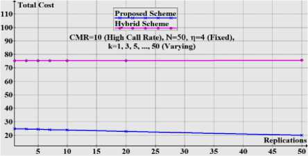
Fig. 8 Total Cost Comparison Varying Replications
In Fig. 9, the value of CMR is fixed at 10 for both the schemes. The threshold values ‘k’ (number of replications) and ‘ η ’ are fixed at 4. The cost of message transfer between VLR and HLR is varying from 25 to 50. We have considered the situation when caller mobile user is far away from its home network and message transfer to HLR is higher. The growth rate of total cost in proposed scheme is very low whereas growth rate in hybrid scheme is high. It indicates that when calling rate of mobile user is high and it is far away from its home network, proposed scheme performs better than hybrid scheme.
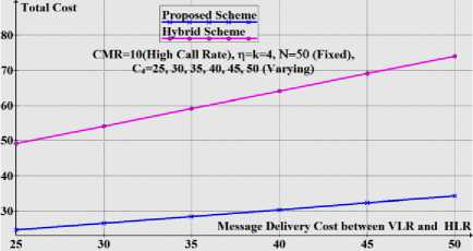
Fig. 9 Total Cost Comparison Varying C4
-
VI. Conclusion and Future Scope
Today the radio spectrum is scarce in wireless communications. For next-generation wireless communication systems, size of cells become smaller and smaller in order to exploit the radio resource efficiently and provide MUs with high QoS. The consequence is the increase in location update messages which consume a lot of bandwidth. As the numbers of MUs are increasing day by day, so location management is still a bigger challenge in the next-generation wireless communication systems. The proposed scheme has been discussed in context of GSM HLR/VLR networks but it is equally useful for next generation networks. The main purpose of the proposed scheme is to reduce call setup cost when calling rate of a mobile user is high. It has been achieved by proposing a replication tree model in which VLRs are attached as per their effective replication probability. It has been observed from the illustrations shown and discussed in section 5 that the proposed scheme outperforms the prior scheme (Hybrid Scheme) in most of the conditions. Further, the proposed scheme adapts immediate update protocol to update the replicas whereas hybrid scheme replies on deferring the update till threshold (no. of VLRs in forwarding pointer chain) reached. The proposed replication tree scheme provides on demand update option of replica at a VLR where mobile user registers its location. The performance of root VLR under heavy traffic load can be considered for further study.
References User's Profile Replication Tree and On Demand Replica Update in Wireless Communication
- R. Jain, Y.B. Lin, C. Lo, and S. Mohan, "A Caching Strategy to Reduce Network Impacts of PCS", IEEE Journal Selected Areas in Communications (1994), Vol. 12, No. 8, pp. 1434-1444.
- N. Shiva Kumar, J. Jannink, and J. Widom "Per-User Profile Replication in Mobile Environments: Algorithms, Analysis and Simulation Results", ACM-Baltzer J. Mobile Networks and Nomadic Applications (MONET) (1997), Vol. 2, No. 2, pp. 129-140.
- Chien-Hsing Wu, Lin Huang-Pao, LanLeu-Sing, "A new analytic framework for dynamic mobility management of PCS networks", IEEE Transactions on Mobile Computing 1 (3) (2002), pp. 208–220.
- Q. Alejandro, G. Oscar, P. Samuel, "An alternative strategy for location update and paging in Mobile networks", Computer Communication 27 (2008), pp. 1509–1523.
- W. Xian, F. Pingzhi, Li Jie, Yi-Pan, "Modeling and cost analysis of movement based location management for PCS network with HLR/VLR architecture, general location area and cell residing time distribution", IEEE Transactions on Vehicular Technology 57 (6) (2008), pp. 3815–3831.
- Md. Mohsin Ali, Md. Ziaur Rahman Khan, and Md. Ashraful Alam, "A Profile-based Two-level Pointer forwarding Cache Scheme for Reducing Location Management Cost in Wireless Mobile Networks", International Journal of Computer Applications (2010), Vol. 3, No.7, pp. 12-18.
- Jie Li, Yi Pan, and Xiaohua Jia, "Analysis of Dynamic Location Management for PCS Networks", IEEE Transactions on Vehicular Technology (2002), Vol. 51, No. 5, pp. 1109-1119.
- Po-Jen Chuang, Shien-Da Chang and Tun-Hao Chao, "Location Tracking in PCS Networks Using Enhanced Caching", Tamkang Journal of Science and Engineering (2009), Vol. 12, No. 1, pp. 29-44.
- Yu Liu, Qiang Shen, Zhijun Zhao and Hui Tang, "Proactive Location Service in Mobility Management", Journal of Networks (2011), Vol. 6, No. 4, pp. 670-677.
- K. Kong, "Performance Analysis of Profile-based Location Caching with fixed local Anchor for Next-generation Wireless Networks", IEICE Transactions on Communications (2008),Vol. E91-B, No. 11, pp. 3595-3607.
- Jinkyung HWANG and Myong-Soon Park, "Adaptive Service Profile Replication Scheme for Next Generation Personal Communication Networks", IEICE Trans. Communication (2003), Vol. E86-B, No. 11, pp. 3344-3351.
- C.R. Kant, P. Arun, and N. Prakash, "Two-level Single-chain Pointer Forwarding Strategy: a new Scheme for Location Management in Mobile Communication", IET Communications (2007), Vol. 1, No. 6, pp. 1224–1229.
- Wenchao Ma and Yuguang Fang, "Two-Level Pointer Forwarding Strategy for Location Management in PCS Networks", IEEE Transactions on Mobile Computing (2002), Vol. 1, No. 1, pp. 32-45.
- Y.B. Lin, "Location tracking with distributed HLR's and pointer-forwarding", IEEE Transaction on Vehicular Technology 47 (1) (1998), pp 58–64.
- Ing-Ray Chen and Baoshan Gu, "Quantitative Analysis of a Hybrid Replication with Forwarding Strategy for Efficient and Uniform Location Management in Mobile Wireless Networks", IEEE Transactions on Mobile Computing (2003), Vol. 2, No. 1, pp. 3-15.
- Wenchao Ma and Yuguang Fang, "A Pointer Forwarding Based Local Anchoring (POFLA) scheme for Wireless Networks," IEEE Transactions on Vehicular Technology (2005),Vol. 54, No. 3, pp. 1135-1146.
- Y. Fang, I. Chlamtac, and Y. B. Lin, "Portable movement modeling for PCS networks," IEEE Transactions on Vehicular Technology (2000), Vol. 49, No. 4, pp. 1356–1363.
- Jyh-Cheng Chen, Jui-Hung Yeh, Shao-Hsiu Hung, Fu-Cheng Chen, Li-Wei Lin, & Yi-Wen Lan, "Reconfigurable Architecture and Mobility Management for Next-Generation Wireless IP Networks", IEEE Transactions on Wireless Communications (2007), Vol. 6, No. 8, pp. 3102-3113.
- 3GPP-TR-23.882, "3GPP System Architecture Evolution: Report on Technical Options and Conclusions (Release 8)," Technical Report, Sept. 2008.
- 3GPP-TR-33.922, "Security Aspects for Inter-Access Mobility between Non 3GPP and 3GPP Access Network (Release 8)," Technical Report, Sept. 2008.
