Using Delaunay triangulation for fingerprint template generation

Author: Gudkov V.Yu., Lepikhova D.N., Gavrilova M.L., Zymbler M.L.
Section: Информатика и вычислительная техника
Article in issue: 3 т.19, 2019.
Free access
Today, fingerprint identification is the most common method of biometric identification. Existing fingerprint identification models have some defects that reduce the speed and quality of identification. So most of the models do not take into account the topological characteristics of images, for example, the classical method of measuring the ridge count value may produce incorrect results in areas of significant curvature of the ridge lines. This paper presents a new mathematical model for fingerprint identification, taking into account their topological characteristics. Identification is performed on the basis of templates. The templates contain a list of minutiae detected on the image and a list of ridge lines. For the ridge lines and minutiae, sets of topological vectors are constructed. The result of building topological vectors does not depend on the location of minutiae and takes into account their possible mutations, which increases the stability of the proposed mathematical model. Additionally, the stability of the model is ensured by combining the base topological vectors constructed for all minutiae and ridge lines into an expanded topological vector. This view allows you to significantly reduce the size of the template and optimize the use of memory. To compare the fingerprints the Delaunay triangulation is used based on the list of constructed topological vectors. 112 possible classes for topological vectors are defined. This approach allows you to increase the speed of identification up to 10 times while maintaining its accuracy. The proposed classification is resistant to rotation and displacement of images.
Fingerprint template, delaunay triangulation, minutiae, topology vector model
Short address: https://sciup.org/147232266
IDR: 147232266 | UDC: 004.93 | DOI: 10.14529/ctcr190303
Применение триангуляции Делоне для формирования шаблона дактилоскопического изображения
На сегодняшний день идентификация по отпечаткам пальцев - наиболее распространенный метод биометрической идентификации. Существующие модели идентификации отпечатков пальцев имеют ряд недостатков, влияющих на скорость и качество идентификации. Так большинство моделей не учитывают топологические характеристики изображений, в частности, классический метод измерения гребневого счета может выдавать неправильные значения в областях значительной кривизны гребневых линий. В статье представлена новая математическая модель для идентификации изображений отпечатков пальцев с учетом их топологических характеристик. Идентификация в рамках предложенной модели выполняется на базе шаблонов. Шаблоны содержат список всех контрольных точек, детектированных на изображении либо на его скелете, и список гребневых линий. Для гребневых линий и контрольных точек строятся наборы топологических векторов. Результат построения топологических векторов не зависит от расположения контрольных точек и учитывает их возможные мутации, что увеличивает стабильность предлагаемой математической модели. Дополнительно стабильность модели обеспечивается путем объединения базовых топологических векторов, построенных для всех контрольных точек и гребневых линий, в расширенный топологический вектор. Такое представление позволяет значительно уменьшить размер шаблона и оптимизировать использование памяти. Для сопоставления отпечатков в предлагаемой модели применяется триангуляция Делоне, которая строится на базе списка построенных топологических векторов. С помощью триангуляции определяются 112 возможных классов для топологических векторов. Такой подход позволяет увеличить скорость идентификации до 10 раз при сохранении ее точности. Предложенная классификация на основе триангуляции Делоне устойчива к поворотам и смещению изображений.
Text of the scientific article Using Delaunay triangulation for fingerprint template generation
Fingerprint images (FI) themselves are not used to identify fingerprints, but templates created on the basis of them using mathematical functions. The bases for the formation of the pattern are minutiae in the form of points of the beginning and ending, merging and bifurcation of the ridge lines [1–3]. They can be detected on the grayscale image, although in the process of creating a pattern, they are more often detected along the skeleton of the ridge lines [4–7] (Fig. 1).
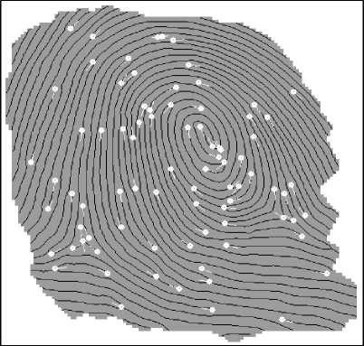
Fig. 1. Skeleton and minutiae
For the reliability of the mathematical model of FI, it must contain the necessary and sufficient number of features [5]. Minutiae, ridge count between them, and also ridge lines in some cases are considered the main informative features [5, 6]. However, most of the models used to prove the uniqueness of the biometric pattern and identification do not contain this in majority [5, 8].
Existing models are focused on improving the accuracy and speed of identification; however, due to the fact that they do not contain sufficiently complete topological information about the image, they all have some drawbacks [9, 10]. For example, the classic method of measuring ridge counting along a straight line can lead to errors in the region of deltas, loops and whorls due to the large
Информатика и вычислительная техника
curvature of the lines in these sections [5]. Thus, the task of forming a FI template, taking into account the topological characteristics of the imprint, remains relevant. The article proposes a new model of representation of the FI pattern, using topological vectors of the ridge lines and calculations based on Delaunay triangulation.
The paper is organized as follows. In the introduction, the basic concepts of the subject area are given, relevance is determined, goals and objectives of the research are set. Section 1 provides an overview of the existing research papers. Section 2 describes the proposed methodology. In the conclusion the results are summarized, the directions of further research are determined.
1. Preliminaries
Delaunay triangulation and Voronoi diagrams are widely used in various fields of science, including the field of biometric identification. Compared to earlier work on the use of computational geometry to improve the results of recognition of biometric information [1, 2], the number of attempts to use the topological and geometric characteristics in the identification process has increased significantly [11].
There have been works on the use of Voronoi diagrams for recognition in biometric systems and the implementation of different approaches to comparing FI [2, 10, 12]. Matching fingerprints based on minutiae is used most often. To do this, a set of minutiae is extracted from the fingerprint image and saved as a set of points on the plane [2, 3, 11]. During correlation matching, the images are directly superimposed on each other, aligned and scaled. For each variant of mutual alignment, the correlation value is calculated [13]. Other methods for matching FI (according to the characteristics of ridge lines based on maps and dictionaries of ridge lines and their geometry [14, 15]) are used much less frequently due to the high complexity of implementation [3]. There have been attempts to apply Voronoi diagrams for other areas of biometrics. For example, to recognize facial features in [12]
Voronoi diagrams can be used to reduce the noise level [14]. The Delaunay triangulation constructed on the basis of a set of minutiae was proposed to be used as a comparative index when comparing fingerprints [1]. To do this, there must be at least one matching pair of triangles for two prints. However, due to the poor quality of images of prints or the low efficiency of algorithms for extracting signs, this condition is not satisfied, and a matching pair is not always detected [16, 17]. This is confirmed by other work, proving that even a small local deformation can lead to significant distortions of the pattern [7].
There were also attempts to use not only two-dimensional (2D) Delaunay triangulation, but also three-dimensional (3D) Delaunay tetrahedron [18]. However these structures are more sensitive to the missing and spurious minutiae, and have a negative impact on the effectiveness of the identification.
It is also possible to use triangulation in hierarchical mode and in combination with other approaches to describing minutiae, for example, in conjunction with constructing a local neighborhood for each minutia by the MCC method [19] or computing of common barycenter for all triangles [20].
The research presented in this paper takes advantage of additional information, which is ignored by fingerprint matching algorithms. It is based on ridge line representation as a clever utilization of Delaunay triangulation [21] and topological vectors [22], which results in increased speed and high recognition capability of the system. The method was fully integrated in a commercial software system [22].
2. Proposed Methodology
The representation of a pattern as a set of FI features may vary in implementations of different developers. In some templates, there is a limit on the number of stored minutiae [5]. Some features of templates are irrelevant, but it is possible to indicate their common property: the templates have features, being some metrics for minutiae points. These metrics are ridge counts between minutiae and topological vector for minutiae [5, 22].
In this paper, an image template is constructed in the form of
Г : F m ) F L m , L , L a } , (1) where F o ( m )=| f/m ) ( x , y )| - image skeleton (Fig. 1); Lm - minutiae list; L z - list of topological vectors for lines; La – list of accelerator vectors for lines. Let’s introduce some definitions.
Definition 1. The skeleton of FI is a graph (u, v^ with nodes u and v . The nodes u and v are lo- cated near the geometric center of the line. For each node P1 e Ци, v) there are two nodes p2 and p3 that are not adjacent to each other.
Definition 2. The skeleton node p 1 , for which there is only one adjacent node p 2 , is called the ending.
Definition 3. If for a skeleton node p 1 there are three adjacent nodes p 2, p 3 and p 4 such that any two nodes from the multitude { p 2 , p3, p 4 } are pairwise non-adjacent, then the node p 1 is called bifurcation.
Minutiae as the nodes of the skeleton represent the nodes of the graph, and based on which the topological characteristics of the FI are determined and a list of accelerator vectors is compiled. All these vectors do not characterize a separate minutia, but the general properties of the ridge lines. Although the L l and La lists store different characteristics of the FI, in general they are very similar, since they are descriptions of all lines of the pattern. This property allows you to keep the small size of templates for quick matching.
-
2.1. Minutiae List
-
2.2. Topological Vectors List
The list of minutiae for the subsequent recognition and matching of fingerprints is formed as follows. Let M i be the minutia with number i . Then the list of all FI minutiae can be written as
L m = { M i = { ( x i ,y i ) , a i , t i , v i , 9 i , Pi , h i } I i e l.. n 1 } , (2)
where ( x i , y i ) , a i , t i , v i , 9 i , p i , h i - coordinates, direction and type of minutiae, as well as value and direction of curvature, probability and density of lines about minutiae; | Lm | = n1 - cardinal number. For reliability of identification, only minutiae from informative areas are taken into account for the template. On Fig. 1 the informative area is highlighted in gray, the skeleton of the image is shown in black.
Coordinates (xi,yi) of minutiae Mi are determined by the location of minutia [5, 6]. Direction az as an angle is determined based on a simple chain of skeleton vertices for the ending and three simple chains for bifurcation [6]. Type ti e{0; 1} where 0 is bifurcation and 1 is the ending, is determined by the vertex valence of the graph representing the image skeleton [22]. Coordinates 9Z, direction az and type t are the basic parameters M [23].
The value vi and the direction of curvature 9Z of the ridge lines are determined within a certain neighborhood of minutia M [4-6]. The probability p is equal to the ratio of the average value of the image quality rating in the neighborhood ε to the best quality rating in the informative area of FI [23]. The density of the lines hi is calculated as the average number of lines located in the neighborhood of ε that the perpendicular crosses to the ridge lines [5, 22]. Typically, a neighborhood ε corresponds to 3–5 periods of lines.
Consider the procedure for building a list of topological vectors for the ridge lines. The list of topo- logical vectors for the lines L is constructed on the basis of the list of the minutiae Lm , the Fo(m) matrix representing the FI skeleton, and other auxiliary matrices that store information about other signs of the FI. Matrices are combined into a pyramid, shown in Fig. 2, and represent the information levels, distributed according to their hierarchical structure [4, 5].
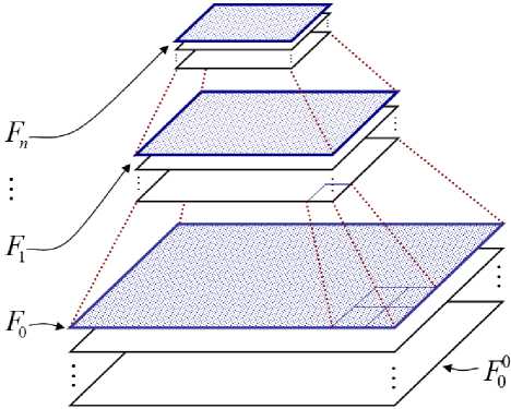
Fig. 2. Layers of the pyramid in the form of a hierarchical structure
The list of topological vectors for the ridge lines of FI is formed from all the skeleton nodes excluding the minutiae and is written as
L = { ^ = { ( e j , « j ,l j ) } I i e l-- n 2 , j e l- m t } , (3) where Vi – topological vector for skeleton nodes cluster; L i ] = n 2 - cardinal number and n 2 > n1 ; i – index of topological vector; j – number of link
Информатика и вычислительная техника
in topological vector; ej – event, and lj – length of link, formed with minutiae with number nj ; m – quantity of links in the intersection with central line, equal to mt = 4 m + 2. (4)
All lists of FI characteristics are based on a similar principle. In the informative area of FI, ridge lines are highlighted and a skeleton is formed. On the skeleton, two types of minutiae are detected: the bifurcations and the endings (Fig. 1) so that the direction of each minutia indicates the area where the number of lines increases [9]. The direction vector of the minutia is parallel to the tangent to the ridge line in some neighborhood of the minutia M i . Each minutia is characterized not only by the number, coordinates and direction, but also by the type, value, direction and density (2) of lines in the neighborhood and other parameters.
Then, for each minutia, perpendiculars to the direction vector to adjacent lines are constructed and points of projections are fixed. In Fig. 3 perpendiculars are shown by a dotted line, and projections are shown with a filled circle.
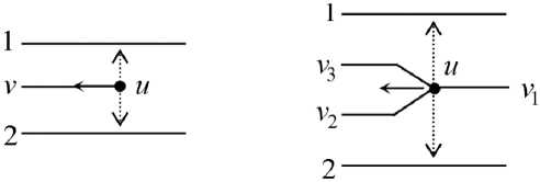
Fig. 3. Projections for ending and bifurcation
The skeleton node p is selected (but not the minutia), and the section through this node is constructed to the right and left to a depth of m lines perpendicular to the tangents to the intersected lines. The obtained points of intersection are called “links” and are numbered, for example, in a spiral, starting from the point pi , in the clockwise direction [22]. The depth of the intersection m can vary from one to eight lines and is the same on the left and on the right. One line forms two links in the intersection. The total number of links is calculated by the formula (4)
The topological vector is formed on the basis of the constructed intersection. For this purpose, all the links, starting from the section and before the meeting with another minutia or its projection on the link, are consistently viewed along the lines. In this case, the following events may be detected (Fig. 4). They are represented in binary code.
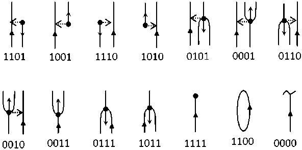
Fig. 4. Events
With the event as a number (there are 14 of them) detected on the link, the number of the minutia that initiates this event is associated. The event is tied to the link number. For events 0000 and 1100, there are no numbers of minutiae, because the line either ends in an uninformative area, or it closes and there is neither a minutia nor a projection on the line. The event and the number of the minutia form an ordered pair ( ej, nj) which is a topological vector corresponding to the link with number j. Then the information about the event is supplemented with the value of the link length from the section to the point at which this event is detected.
To construct an extended topological vector, use an ordered triplet ( ej , nj , lj ) from the event, the number of the minute initiating the event, and the length of the link. The lengths of links, broken on FI edge, are stable in the meaning that they are not shortened in case of fool rolling of the finger.
By the location of the bits in the event, you can determine the type of minutia, its direction and location relative to the course of link. Events allow on-the-fly compare the basic topological vectors and speed up the identification procedure.
Topological vectors are built for all nodes of the skeleton pi (but not for the minutiae). In this case, the ridge lines of FI are divided into links numbered in a spiral in a clockwise direction. Fig. 5 shows the section for the skeleton node A , which ends with ending 19. The resulting cross-section links are numbered 0–17. The result of constructing a topological vector for node A is shown in Table 1.
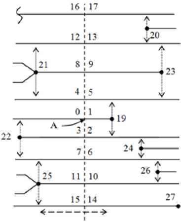
Fig. 5. Section for line with ending
Topological vector for A and B
|
No. |
Event |
Index |
Size |
|
0 |
1110 |
22 |
l 0 |
|
1 |
1111 |
19 |
l 1 |
|
2 |
1110 |
19 |
l 2 |
|
3 |
1111 |
22 |
l 3 |
|
4 |
0001 |
21 |
l 4 |
|
5 |
1101 |
19 |
l 5 |
|
6 |
1010 |
24 |
l 6 |
|
7 |
0010 |
25 |
l 7 |
|
8 |
0011 |
21 |
l 8 |
|
9 |
1111 |
23 |
l 9 |
|
10 |
1010 |
26 |
l 10 |
|
11 |
0011 |
25 |
l 11 |
|
12 |
0010 |
21 |
l 12 |
|
13 |
1010 |
20 |
l 13 |
|
14 |
1111 |
27 |
l 14 |
|
15 |
0001 |
25 |
l 15 |
|
16 |
0000 |
– |
– |
|
17 |
1001 |
20 |
l 17 |
Table 1
|
No. |
Event |
Index |
Size |
|
0 |
1110 |
22 |
l 0 |
|
1 |
1011 |
19 |
l 1 |
|
2 |
0111 |
19 |
l 2 |
|
3 |
1111 |
22 |
l 3 |
|
4 |
0001 |
21 |
l 4 |
|
5 |
0101 |
19 |
l 5 |
|
6 |
0110 |
19 |
l 6 |
|
7 |
0010 |
25 |
l 7 |
|
8 |
0011 |
21 |
l 8 |
|
9 |
1111 |
23 |
l 9 |
|
10 |
1010 |
26 |
l 10 |
|
11 |
0011 |
25 |
l 11 |
|
12 |
0010 |
21 |
l 12 |
|
13 |
1010 |
20 |
l 13 |
|
14 |
1111 |
27 |
l 14 |
|
15 |
0001 |
25 |
l 15 |
|
16 |
0000 |
– |
– |
|
17 |
1001 |
20 |
l 17 |
In the section for the skeleton node B , which ends with bifurcation 19, and the links are enumerated as 0–17. For node B the topological vector is also presented in table 1. The section is shown by a dotted line. Also Fig. 6 shows the mutation [22] of the ending 19 to bifurcation 19. One of the variants of the occurrence of such a mutation is the noise of the image of the print. Essentially, the nodes A and B are the same.
The choice of the point from which the numbering of links in the section begins for the nodes A and B (the link with the number 0) does not play a special role, since the cases of mirroring of the numbering are easily recognized and taken into account directly by identification. Matching of the constructed sections is performed by analogy with the game “Puzzle” by connecting the corresponding connectors. For a section with depth m = 4, m t = 18 links are formed according to formula (4).
Информатика и вычислительная техника
The number of topological vectors for FI can be estimated. On Fig. 5, the two-forked dotted arrow indicates the zone between the minutiae 19 and 25, within which the displacement of point A along the line of the skeleton does not affect the synthesized vector. The similar zone between the minutiae 19 and 20 for point B is shown in Fig. 6. If the basic topological vectors coincide, then they are combined into one, in which the minimum bond length is maximum. So, the total number of topological vectors decreases tenfold from n 2 < 1000 to n 1 < 1000 according to (3). Deformation of the image does not significantly affect the basic vector [22].
The proposed methodology has series of advantages. Firstly, at the events calculation the projection of minutiae is used, that result in prevention of the information loss. Secondly, the links enumerating is turning along the gyrate without links omission. Thirdly, at integration it is possible to choose topological vector with maximum value of minimal length of link [22]. This raises stability and comprehension of the mathematical model.
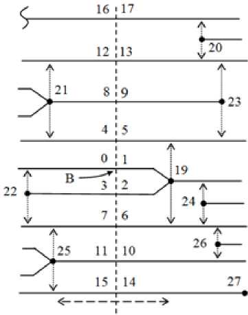
Fig. 6. Section for line with bifurcation
-
2.3. Delaunay triangulation
After forming the list of topological vectors for their matching, it is possible to construct the Delaunay triangulation, which is built on the basis of the minutiae list L m by the formula (2). For the skeleton node A (see Fig. 5), one of the constructed triangles is shown in Fig. 7. The vertices of this triangle are minutia { U i | U i e L m , I e 1..3 } and { U z} = { M} | M} e Lm , j e { 22, 21,19 } } respectively. By definition,
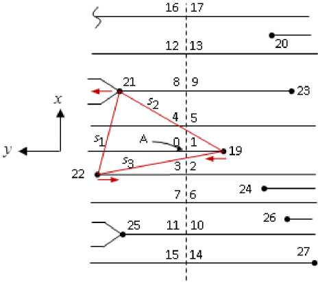
Fig. 7. Delaunay triangulation for node A
the circle described around any triangle from the constructed triangulation does not contain other points from Lm .
To select an initial point for triangulation, let node A be inside the circle described around the marked triangle. Then the topological vector for the node A section divides the FI into two areas. The ordinate axis will be directed to the area with a large number of vertices of the marked triangle, the abscissa axis coincides with the section. Then the starting point of the triangulation U s has a positive ordinate and the minimum abscissa value. In Fig. 7 minutia number 22 corresponds to the starting point of Us .
Starting with Us , go round all the vortexes of the triangle clockwise, comparing the lengths of its sides s 2 > s 3 , s 3 > s 1 , and form three bits γ 1 , γ 2 , γ 3 , where у e { 0; 1 } that define the comparison results.
The following states are possible: 110, 011, 101, 100, 010, 001 and 000, with the latter corresponding to an equilateral triangle.
Based on the events in the topological vector constructed for node A , it can be seen that the direction of the minutia 22 is opposite to the direction of communication. Therefore, the value of the bit is γ 4 = 1. Going around the vertices of the triangle clockwise, we get γ 5 = 0 (the direction of the minutia coincides with the direction of the connection) and γ 6 = 1. For a random distribution of minutiae, eight states are possible for the values of γ 4 , γ 5 , γ 6 .
Node A is on the line starting from minutia 19. If the direction of the node coincides with the direction of the axis of ordinates for the topological vector, then bit γ 7 = 1, otherwise γ 7 = 0.
Calculated bits C = { y k | k е 1..7 } assume 112 possible states (7 x 8 x 8). These bits are not correlating. There density of distribution is inhomogeneous. The formed 112 descriptors allow for the preliminary classification of topological vectors and sets of minutiae. This classification is resistant to rotations and displacements of images. For the cardinal number of vectors n 2 (3), the list of accelerator vectors can be written as
L a = { c = { y k I k eL7} | i e l.. n 2 } . (5)
Conclusion
The paper presents a mathematical model for the FI identification using topological vectors for the ridge lines. The constructed topological vectors are combined into a connected graph with a high level of redundancy. This allows to link subgraphs of different informative areas of fingerprints. The list of topological vectors for the ridge lines Ll according (3) can be represented in a short version (without lengths of links). Possible mutations of the minutiae do not violate the numbering of links and the order of consideration of the minutiae (table 1). The base topological vectors can be combined into one extended topological vector with maximum length of the minimum link. This increases the stability of the proposed model.
Delaunay triangulation ensuring the reliability of the proposed model and increase the identification rate about ten times. For testing, we used fingerprints obtained from an optical sensor from FVC2000 DB3, FVC2002 DB1, FVC2004 DB1, FVC2006 DB2.
The main characteristics of FI are presented in the form of lists complement each other. The list of topological vectors can be stored in shorted form (without the link lengths). This allows to optimize the amount of memory and reduce the size of the template.
References Using Delaunay triangulation for fingerprint template generation
- Bebis G., Deaconu T., Georgiopoulos M. Fingerprint Identification Using Delaunay Triangulation // Proc. 1999 International Conference on Information Intelligence and Systems (ICIIS99). Washington, DC, 1999, pp. 452-459. DOI: 10.1109/iciis.1999.810315
- Jain A.K., Hong L., Bolle R. On-line Fingerprint Verification // IEEE Transactions on Pattern Analysis and Machine Intelligence, 1997, vol. 19, no 4, pp. 302-313. DOI: 10.1109/34.587996
- Jiang X., Yau W.-Y. Fingerprint Minutiae Matching Based on the Local and Global Structures // Proc. 15th Internet Conference Pattern Recognition (ICPR, 2000). Barcelona, Spain, 2000, vol. 2, pp. 1042-1045. DOI: 10.1109/ICPR.2000.906252
- Gonzalez R., Woods R. Digital Image Processing, 2006.
- Maltoni D., Maio D., Jain A.K. Handbook of Fingerprint Recognition. New York, Springer-Verlag, 2003. 348 p. DOI: 10.1007/978-1-84882-254-2
- Местецкий Л.М. Непрерывная морфология бинарных изображений. М: Физматлит, 2009. 288 p.
- Ali H.M., Corraya S. Line Profile-Based Fingerprint Matching // Proc. 2016 International Workshop on Computational Intelligence (IWCI). Dhaka, Bangladesh, 2016, pp. 115-119.
- DOI: 10.1109/IWCI.2016.7860350
- Kamath S.K.M., Rajeev S., Panetta K., Again S.S. Fingerprint Authentication Using Geometric Features // Proc. 2017 IEEE International Symposium on Technologies for Homeland Security (HST). Waltham, MA US, 2017, pp. 1-7.
- DOI: 10.1007/s10044-003-0201-2
- Kovacs-Vajna Zs., Miklos A. Fingerprint Verification System Based on Triangular Matching and Dynamic Time Warping // IEEE Transactions on Pattern Analysis and Machine Intelligence, 2000, vol. 22, no. 11, pp. 1266-1276.
- DOI: 10.1109/34.888711
- Liang X., Asano T., A Linear Time Algorithm for Binary Fingerprint Image Denoising Using Distance Transform // IEICE TRANSACTIONS on Information and Systems, 2006, vol. E89-D, no. 4, pp. 1534-1542.
- DOI: 10.1093/ietisy/e89-d.4.1534
- Wayman J., Jain A.K., Maltoni D., Maio D. Biometric Systems: Technology, Design and Performance Evaluation. Springer-Verlag, 2006.
- DOI: 10.1007/b138151
- Xiao Y., Yan H. Facial Feature Location with Delaunay Triangulation / Voronoi Diagram Calculation // Proc. Selected Papers from 2001 Pan-Sydney Area Workshop on Visual Information Processing (VIP2001), CRPIT, vol. 11. Feng D.D., Jin J., Eades P. and Yan H., Eds. ACS, 2002, pp. 103-108.
- Ratha N.K., Karu K., Chen S., Jain A.K. A Real-Time Matching System for Large Fingerprint Databases // IEEE Transactions on Pattern Analysis and Machine Intelligence, 1996, vol. 18, no. 8, pp. 799-813.
- DOI: 10.1109/34.531800
- Liao C.C., Chiu C.-T. Fingerprint Recognition with Ridge Features and Minutiae on Distortion // Proc. 2016 IEEE International Conference on Acoustics, Speech and Signal Processing (ICASSP). Shanghai, China, 2016, pp. 2109-2113.
- DOI: 10.1109/ICASSP.2016.7472049
- Liu E., Cao K. Minutiae Extraction from Level 1 Features of Fingerprint // IEEE Transactions on Information Forensics and Security, 2016, vol. 11, no. 9, pp. 1893-1902.
- DOI: 10.1109/TIFS.2010.2103940
- Wang H., Gavrilova M., Luo Y., Rokne J. An Efficient Algorithm for Fingerprint Matching // Proc. International Conference on Pattern Recognition (ICPR 2006), Hong Kong, 2006, pp. 1034-1037.
- DOI: 10.1109/ICPR.2006.236
- Wang C., Gavrilova M. Delaunay Triangulation Algorithm for Fingerprint Matching // Proc. 2006 3rd International Symposium on Voronoi Diagrams in Science and Engineering (ISVD 2006), Alberta, Canada, 2006, pp. 208-216.
- DOI: 10.1109/ISVD.2006.19
- Macedo M.J., Yang W., Zheng G., Johnstone M.N. A Comparison of 2D and 3D Delaunay Triangulations for Fingerprint Authentication // Proc. 15th Australian Information Security Management Conference. Perth, Australia, 2017, pp. 108-115.
- DOI: 10.4225/75/5a84f3ca95b4b
- Dremin A., Khachay M., Leshko A. Fingerprint Identification Algorithm Based on Delaunay Triangulation and Cylinder Codes // Proc. Third International Conference on Analysis of Images, Social Networks and Texts (AIST 2014), Yekaterinburg, Russia, 2014, pp. 128-139.
- DOI: 10.1007/978-3-319-12580-0_13
- Elmouhtadi M., Elfkihi S., Aboutajdine D. Fingerprint Identification Based on Hierarchical Triangulation // Journal of Information Processing Systems, 2018, vol. 14, no. 2, pp. 435-447.
- DOI: 10.3745/JIPS.02.0084
- Ghaddab M.H., Jouini K., Korbaa O. Fast and Accurate Fingerprint Matching Using Expanded Delaunay Triangulation // Proc. IEEE/ACS 14th International Conference on Computer Systems and Applications (AICCSA). Hammamet, Tunisia, 2017, pp. 751-758.
- DOI: 10.1109/AICCSA.2017.33
- Sparrow M.K. Vector Based Topological Fingerprint Matching. Patent 5631971 USA, Int. Cl. G 06 K 9/00. Field Jul. 15, 1994; Date of patent May. 20, 1997; U.S.Cl. 382/125.
- ISO/IEC Information Technologies. Biometrics. Biometric Data Interchange Formats. Part 2. Finger Minutiae Data, 2011.
