Using of electromagnetic and acoustic interaction for submarine telecommunications

Author: Shaidurov Georgy Ya., Kudinov Danil S.
Journal: Журнал Сибирского федерального университета. Серия: Техника и технологии @technologies-sfu
Article in issue: 3 т.8, 2015.
Free access
The article describes the potentiality of submarine reception of radio signals emitted by shore radio transmitter with a horizontal antenna in the wavelength range based on interaction radio and acoustic waves in skin-layer.
Radio, telecommunication, sea water, conductivity, acoustic waves, .s. // journal of radioelectronic. 2012. № 2. p. 1-5. [3] solovyov v.i, novik l.i, morozov
Short address: https://sciup.org/146114960
IDR: 146114960 | UDC: 621.396.944
Использование взаимодействия электромагнитных и акустических волн для подводной радиосвязи
В статье рассматривается взаимодействие электромагнитных и акустических волн в ионопроводящих средах, в частности, в морской воде для решения прикладной задачи обеспечения радиоприема подводными аппаратами на больших глубинах.
Text of the scientific article Using of electromagnetic and acoustic interaction for submarine telecommunications
The need for the reception of radio signals under water without surfacing of underwater vehicle (UV) emerges in many problems of both military and civilian technology, in particular for navigation and control of the UV including the under-ice diving, during the seismic sensing of the earth in the Polar Regions, when the sea surface is tightly covered with pack ice.
Consider the problem of signal reception under the sea surface making use of the effect of signal heterodyning in the skin layer of the electromagnetic wave by «highlighting» the water by ultrasound from the board of an underwater vehicle (Fig. 1).
In the figure, the electromagnetic wave (EW) emitted by coastal or aeronautical radio station carrying the message signal becomes elliptically polarized at the border water-air with a vertical component of the electric field E 1z and horizontal components of the electric and magnetic fields E 1x and H 1y respectively. At the same time the water surface is irradiated with directional acoustic radiation 3, formed by means of ultrasonic emitters located on the hull of the underwater vehicle 4 (UV). As a result of parametric interaction of the horizontal component of the electric field E 1x of frequency f e with a power flux of the acoustic radiation of frequency f a the residual signal of frequency F = f e – f à is formed in the skin layer of the E-field radiation falling onto the surface. Subject to validity of the ratio F>>f e the electromagnetic signal of difference frequency penetrates to a depth h with a much smaller absorption as compared to the signal of frequency f e and is received by the UV. The intensity vectors E 2x and H 2y of the EM field of the difference frequency F create signals of informational message at the receiving antennas of the UV.
The traditional scheme of underwater reception of radio signals today is realized by means of receiving by an electric antenna towed by the UV (floating cable), with a diving depth of UV of about 100m. Direct reception by the antenna, located on the UV, depending on the carrier frequency f e , is possible on the depths of about 10 m in the frequency range 50-100 kHz and 100-150 m in the range of hundreds of Hertz.
It is interesting to evaluate the possibility of reception of radio signals by means of the parametric method. Because of the complexity of the problem we give an approximate estimation of parameters of the radio signal: signal strength, SNR for given values of rate of data transmission for the case of a plane wave in the reception area and the equivalent linear model (virtual) electromagnetic signal transmitter at the difference frequency F , formed in the interaction area between acoustic and electromagnetic waves on the water surface.
In the case of plane wave intensities of the field of difference frequency can be defined as:
E 2 x = E 1 znEm σ e - F (1)
H 2 y = H 1 ym σ e -δ F h (2)
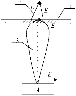
Fig. 1. Radio reception by means of parametrical method: 1 – components of the electromagnetic wave vector; 2 – water surface; 3 – pattern of the acoustic radiation; 4 – UV
ωε where nE= E 0 – is the refraction coefficient of electromagnetic wave at the water-air boundary;
σ
Δσ 1
m σ = – is the relative increment of electro conductivity of water. In these formulas ε 0 = ⋅ 10 9 –
σπ is the permittivity of free space; ωE =2πfэ – is the carrier frequency.
Equation (2) is determined by the approximate Leontovich boundary conditions [3] and corresponds to the continuity of the horizontal component of the magnetic field at the water-air boundary.
In accordance with [4, 5]:
m =1.75⋅10-6 I, (3)
σ where I – stands for the intensity of acoustic radiation at the surface of water in W/m2.
When using the receiver electrical antenna of length, located on the UV, the received signal of frequency ωм =2πF can be found using the relation: м
U 2 E = E 2 x L A . (4)
For the case of the magnetic antenna:
U = H µω S , (5)
2H2y0м A where µ0 =4π⋅10-7 H/m2 – is the magnetic permeability of free space; SA –is the effective area of the receiving magnetic antenna.
Consequently, the signal at the output of the receiving antennas can be estimated as:
P = U2E П A ; P = Ц ^ , E Rin Í R in
where Rin – is the input resistance of the receiver, is η A – the transmission coefficient of antenna feeder.
The total power of external interference and the intrinsic noise of the receiver can be written as:
Bi = Dei + Dn ,
where В. = Ш
EI Rin
Uin – stands for the amplitude of the external electromagnetic noise, at a depth h ;
Dm = kT0&F - is the power of thermal noise of the receiver; K = 1 38 • 10-23 W' Hz — is the Boltzmann’s Nk deg constant; Tk0 - is the temperature of the input circuits of the receiver; and ΔF – is the bandwidth of the receiver.
External noise at the difference frequency F attenuates in seawater in the same way as the received electromagnetic signal at this frequency.
E 2 1 = ^ 1 i e -Ъ F h
H 2 1 = H 1 i e" F h
Consequently:
U = e X l ; U H = H ц0 SA to,.
XI 2 IA YI I 0 Aì
We allow to determine the required intensity of the electrical component of the field of the signal at the surface of the water as:
E i , =
' q (H11 )2 У m о B
V V

• HI- 120 n • mE
Here H 1 I = —— . Taking this into account 120 n
Ez ^l-l
V B )
E 1 I m a
From (11) it is obvious that the reliability of receiving messages depends on the parameters q , B , m E ( f e , σ, I ).
On the surface of the sea the level of the horizontal component of the electric field corresponds to the frequency range of 100-1000 Hz (-140) to (-160) dB/V2/m2 Hz.
The magnetic field intensity of noise on the surface of the water is: H„ = (-120)+(-140) dB/V2/ m Hz.
If H 1 I = 10–6 A/m•Hz; m σ = 10–3; q = 10; we obtain from (11) a numerical estimate of the required field intensity at the receiving point:
H1z = 20 · 10–4 V/m = 2 mV/ m•Hz.(12)
The estimation F 1 z according to (14) F 1 I = 160 dB/V2/m2 gives:
< A/2 m-8 , , , ,
E ,z =|—— I • "0т = 10 - 4 V m4Hz = 100 ц V mM.
1 z V1000 J 10-3 '
Since the impedance of air is W = 377 Ohms, the magnetic field intensity of noise corresponding to the level of E 1 z (13) is equal to:
HU = E z = 101 = 0.27•Ю - б Afm4Hz -
1 I W 377
According to other data [2], the level of atmospheric noise at a frequency of 100 Hz corresponds to Ex A ® 200ц V/m V Hz . In this case it is necessary to ensure that on the surface of the sea:
E1 z = 0,1 • ^00- = 20ц V m.Hz -
10
Thus, according to various estimates, the required electric field strength at the sea surface varies over a wide range from an acceptable value (13), (14) to an unattainable at long distances (15). Note that these estimates do not take into account the depth of the UV and the required transmit power of the station is determined only by the level of uncorrelated noise at the sea surface.
Since the magnitude of the electrical conductivity of water is mainly determined by the concentration of ions of impurity salts, the oscillating pressure of the ultrasound, causing an intense shift of the impurity ions in the direction of the power flux of sound, leads to an intense increase of conduction current, which explains the above mentioned effect of ultrasound on the electrical conductivity. At the modulation frequency F = fe- fa =1 Hz signal reception is possible at a depth of 100 m, which is unattainable using any other method of transmission.
References Using of electromagnetic and acoustic interaction for submarine telecommunications
- Romanova G.N., Shaidurov G.Ya.//Journal of Communications Technology and Electronics. 1991. T. 36. № 2. P. 410.
- Shaidurov G.Ya., Kudinov D.S.//Journal of Radioelectronic. 2012. № 2. P. 1-5.
- Solovyov V.I., Novik L.I., Morozov I.D. The sea communication. L.: Sudostroenie, 1978. (Rus).
- Shaidurov G.Ya., Lukyanchikov V.N., Romanova G.N.//Journal of Communications Technology and Electronics. 1985. T. 30. № 11. P. 21-36.
- Popov N.I., Fyodorov K.N., Orlov V.M. The sea water. M.: Nauka, 1979. 310 p.
