Utilization of viscoelatic models with non-linear springs and dashpots in delamination study of multilayered beams

Author: Rizov V.I.
Article in issue: 1, 2022.
Free access
This paper analyzes delamination of multilayered inhomogeneous beam structure by utilization a non-linear viscoelastic mechanical model. The non-linear time-dependent response is treated by a non-linear spring and a non-linear dashpot connected in series to a system of two linear springs and two linear dashpots. The model is under stress that is a linear function of time. The constitutive law of the model representing a non-linear dependence between stress, strain and time is derived. The main goal of the paper is to obtain a solution of the strain energy release rate for the delamination in the multilayered inhomogeneous beam by applying the non-linear viscoelastic model. Solutions are derived by using the complementary strain energy and by analyzing the balance of the energy with taking into account the non-linear viscoelastic behaviour. For this purpose, the constitutive law of the non-linear viscoelastic mechanical model is used. The solutions are applied to obtain results for multilayered beams with non-linear variation of material properties in longitudinal direction. The influence of different parameters on the time-dependent strain energy release rate is assessed. The study indicates the effectiveness of the viscoelastic mechanical models with non-linear springs and dashpots in time-dependent delamination analyses of multilayered inhomogeneous beam structures.
Inhomogeneous material, multilayered beam, non-linear springs and dashpots, delamination, non-linear viscoelastic behavio
Short address: https://sciup.org/146282438
IDR: 146282438 | UDC: 531
Text of the scientific article Utilization of viscoelatic models with non-linear springs and dashpots in delamination study of multilayered beams
ВЕСТНИК ПНИПУ. МЕХАНИКА № 1, 2022PNRPU MECHANICS BULLETIN
In contemporaneous engineering practice very often load-bearing engineering structures are subjected to heavy loadings and extreme external influences. At the same time, all the requirements towards the engineering structures have to be satisfied with minimum expenditure of materials not only because of the cost but also because of the fact that the weight of structures is usually an issue. This situation leads to necessity of introduction of new structural materials of adequate properties to withstand the complicated conditions of work. One type of such materials is continuously inhomogeneous structural materials [1–12]. One of the most important peculiarities of these materials is the fact that their properties vary smoothly along one or more coordinates in the structural member [13–15]. In the last four decades, the most widely used continuously inhomogeneous materials are the functionally graded materials [16–23]. They represent continuously inhomogeneous composites made by mixing of two or more constituent materials. The microstructure and the properties of the functionally graded materials can be


Эта статья доступна в соответствии с условиями лицензии Creative Commons Attribution-NonCommercial 4.0 International
License (CC BY-NC 4.0)
This work is licensed under a Creative Commons Attribution-NonCommercial 4.0 International License (CC BY-NC 4.0)
formed technologically during the production process [24–34]. In this way, highly sophisticated structural members with different material properties in different parts of a member can be manufactured.
Multilayered inhomogeneous materials representing systems of adhesively bonded layers are frequently applied in various load-bearing structures in modern engineering [35–44]. Structural members made of multilayered materials have various advantages in comparison with the homogeneous load-bearing structures. For instance, the strength-to-weight and stiffness-to-weight ratios of multilayered systems are higher. Although the concept of multilayered materials is rather efficient, the multilayered structural members are highly sensitive to delamination (separation) of layers [45–48]. Delamination can grow rapidly causing the failure of the multilayered inhomogeneous structure with catastrophic consequences. There are various factors which affect the delamination behaviour. The effects of these factors have to be analyzed at length in order to improve the knowledge on the delamination. This knowledge can play an important role in safety design of load-bearing multilayered structural components.
Usually, the multilayered inhomogeneous materials have non-linear viscoelastic behaviour. Therefore, non-linear viscoelastic mechanical models have to be utilized in timedependent delamination analyses of multilayered structures.
For this purpose, in the present paper, a model representing a combination of linear springs and dashpots is modified by introducing a non-linear spring and a nonlinear dashpot. In this manner, a non-linear viscoelastic model is obtained. This model is utilized in a delamination analysis of a multilayered inhomogeneous beam. A solution of the strain energy release rate is derived. The balance of the energy is analyzed to verify the solution. When deriving the solution, the constitutive law of the non-linear viscoelastic model is used to describe the mechanical behaviour of the beam structure. It should be noted that this paper develops further the approach presented in [49; 50]. The main novelty is that a non-linear viscoelastic model is utilized in contrast to [49; 50] where delamination is analyzed by using viscoelastic models assembled by linear springs and linear dashpots.
Analysis of the time-dependent strain energy release rate
The mechanical model presented in Fig. 1 exhibits nonlinear viscoelastic behaviour due to the non-linear spring, npi , and the non-linear dashpot, nwi , which are added to the linear springs with modulae of elasticity, EBi and EDi , and linear dashpots with coefficients of viscosity, η Bi and η Di .
The model in Fig.1 is under stress, σ i , that varies with time, t , according to following equation:
° i = v ° i t , (1)
where v σ i is a parameter that governs the loading.
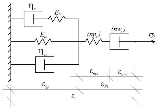
Fig. 1. Non-linear viscoelastic model
The constitutive law of the model represents a nonlinear dependence between stress, strain and time (the nonlinearity is generated by the non-linear spring and dashpot). In order to derive this constitutive law, first, the strain, ε i , is expressed as (Fig. 1)
6 i = 6 Qi + 6 Ri ’ (2)
where ε Qi is the strain in the spring with modulus of elasticity, EBi , and in the dashpot with coefficient of viscosity, η Bi . The strain, ε Ri , is written as
6 Ri 6 npi + 6 nwi i
where ε npi is the strain in the non-linear spring, ε nwi is the strain in the non-linear dashpot as shown in Fig. 1.
The mechanical behaviour of the non-linear spring is described by the following non-linear stress-strain relationship [51]:
σ npi
Hi ε npi
V1 + 62 Pi'
where σnpi is the stress in the spring, Hi is a material property. From Fig. 1, it is obvious that
° npi = ° i •
After substituting of (5) in (4) and performing some mathematical transformations, one derives
ε npi
σ i
The response of the non-linear dashpot is treated by using the following relationship:
σ nwi
L £ inwi
where Li and f i are material properties, 6 nwi is the first derivative of the strain with respect to time. By using (7) and taking into account that (Fig.1)
nwi i , one derives
δ EEv
Yu = /■ Y2 i = Dr^ , Y2 i = -Л , YM =
δ1 i δ1 i δ1 i δ1 i
|
• _ G i |
(9) |
|
ε nw . AL 2 — f 2g2 |
|
|
By substituting of (1) in (9), one obtains |
|
|
vt е g - |
(10) |
|
™ — f’v G - t 2 |
Equation (10) is solved with respect to ε nwi . The result is
η Di η Bi Di
U1 i ’ U2 i 'I Di + 'I Bi + 'I Bi" (21)
EBi EBi
The solution of (20) is found as еBi (t) = AZBP2Lew + BiP1--- Ai ep2-t + Ait + в, (22)
P2i — Pli P2i — P1i where
-
е™= 1- V l 2- f2 v2t2 + C,(11)
nwi 2 i i σi1
-
fi v σ i
where C1 is an integration constant. Since е nwi( °) = 0,(12)
one derives
C = / .(13)
-
fi 2 v σ i
A i = — , B i = — U/ '. G , P l i = - 0 "5V 1 i +v , ψ2 i ψ22 i δ1 i
P z i = 0 "5 ( V 2 i - 4V 2 i ) °'5 , p 2 i =- 0"5V 1 i - P z i " (23)
By combining of (1), (19) and (21), one derives
ел; (t ) = g -X, e P 1 + g X-) e p 2 +— i— g. —^ i —+
Qi i 1 i i 2 i i
δ1 i ψ22 i δ1 it
By combining of (11) and (13), the strain in the nonlinear dashpot is found as
е ... = f L - 7 L 2 - f2v 2 t 2 J . (14)
Ji v G i X J
+ ' Bi 2 i I p^X e Pl i t + Р2Л2 e92, 1 +—“ l> (24)
1 i 1 i 2 i 2 i
EBi X ^it J where
X = v 2 i + V 1 i , X = ^V 1 i P i zy 2^,
1 ( p 2 i - P 1 i ) ^ ^^и1’ 2 i ( p 2 i - P 1 i ) v 2 i 51 it’
The next step is to obtain the strains in the linear springs and dashpots. For this purpose, the following equation of equilibrium is used:
x = у 2 - +У 1 -
1 ( p 2 i -P 1 i ) v 2 i 5 1 it"
σ
η Di
+ Gr + G
E Di η Bi
= G i ,
X i = -Уп-р -- - v 2 -
( p2 i — P l i ) V 2 i ^ i i t
where σ , σ and σ are the stresses in the spring with 4Di EDi ' Bi coefficient of viscosity, ηDi , in the spring with modulus of elasticity, EDi , and in the dashpot with coefficient of viscosity, ηBi , respectively (Fig. 1). These stresses are expressed as
2 Di = е ei n d- , G E Di = EDi е Qi '
2 Bi = П Bi e Bi ,
where е Bi is the first derivative of the strain in the dashpot with coefficient of viscosity, η Bi . The stress in the spring with modulus of elasticity, EBi , is equal to ση Bi
E Bi ( е Qi е Bi ) = ' Bi e Bi" (19)
By using of (15)–(19), one obtains еBi+ Y^Bi + ^2-^Bi = ^it , (20)
where
By using of (1), (2), (3), (6), (14) and (24), one obtains the following non-linear constitutive law that relates time, stresses and strains in the model in Fig. 1:
е, (t) = g,X,eP1 t + g,.X2eP2t + ^i- — g,. ^^i—+ ii1i i2ii
δ1 i ψ2 i δ1 it
+“^BiPii^i ,eP1 -t + p2i^2 eP2 it +|+-+
E b- X 1 - 2- 5 1 - t J
[ L - 4L-2— Ji2g2 J .(27)
Ji 2 i X
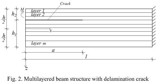
The constitutive law (27) is applied for treating the time-dependent mechanical behaviour of the -th layer in the multilayered inhomogeneous non-linear viscoelastic beam structure in Fig. 2 when deriving a solution of the strain energy release rate.
The beam consists of an arbitrary number of adhesively bonded layers with different thicknesses and material properties. The cross-section of the beam is a rectangle of width, b , and thickness, h . The beam length is denoted by l . The beam is clamped in its right-hand end. A delamination crack
и * = и * + и * , (33)
where U 1 * and U 1 * are the complementary strain energies in the upper delamination crack arm and in the un-cracked beam portion, 0 < x < l , respectively. The complementary strain energy, U 1 * , is found as
U * = 2 b J f u * idxdz1 , (34)
i = 1 0 Zi .
of length, a , is located between layers so as the thicknesses of the lower and upper delamination crack arms are h 1 and h 2 , respectively. The beam is loaded by a bending moment, M , applied at the free end of the upper crack arm. Therefore, the lower crack arm is free of stresses. The bending moment varies with time according to the following dependence:
M = vt ,
where v is a parameter that controls the loading.
The layers exhibit continuous material inhomogeneity along the beam length. The following dependences are used for describing the variation of the material properties involved in the constitutive law (27) in the longitudinal direction in the i -th layer of the beam:
P — P I EB to i EBai Y"1 i p — P i ED и i EDai Y"2 i
EBi EB ai + i "1 i x , EDi ED ai + i "2 4
n Bi= n B ai+ Г l Г x "3',(29)
n Dmi - n D a i v"4 , H mi - Hai v 5 i„
'I Di 'IDai + i "4 i x , Hi H ai + i "5 ■
where m 1 is the number of layers in the upper crack arm, u * 0 i is the complementary strain energy density in the i -th layer, z 1i and z 1 i + 1 are, respectively, the coordinates of the upper and lower surfaces of the layer, z 1 is the vertical centroidal axis of upper crack arm cross-section.
Due to non-linear character of the constitutive law (27), the stress can not be determined explicitly. Therefore, the complementary strain energy density that is involved in (34) is obtained as
σi u 0,-= J
ε id σ i .
By combining of (27) and (35), one derives

Xue P 1 1 + X 2i e p 2 t
η B σ 2
1 ψ1 i
^^^^^^^^^^^^^^^f ^^^^^^^ ^^^^^^^^^^^^^^^^^^^^^^^^^^^^^^^^^^^s δ1 i ψ22 i δ1 it
+
where
L = L + Ltoi Lai x"6.,(30)
iαi lμ6i
0 < x < l,(31)
i = 1,2,..., m.(32)
2 E B
P l i ^ l i e P 1 ' t + P 2i4 e Рг‘ ‘
^^^^^^^
Lt
° 2 + - i? ifi 2
I +
S l i t J
^^^^^^^
1 I ^i /V2 2 L fi^i I
/L 2 — f ^° 2 +—— arcsin i2—i . (36)
f ^o i ( 2 ' ' ' 2 f
The boundaries of integration, z1i and z1i + 1 , in (34) are replaced with G B i and а я , respectively (here, G B i and а я are the stresses in the upper and lower surfaces of the layer, respectively)
In formulae (29) and (30), EBαi , EDαi , ηBαi , ηDαi , Hαi and L are the values of E , E , η , η , H and L at αi Bi Di Bi Di i i the free of the beam, respectively. The values of EBi , EDi , ηBi , ηDi , Hi and Li at the clamped end of the beam are EBωi , EDωi , ηBωi , ηDωi , Hωi and Lωi , respectively. The parameters, μ1i , μ2i , μ3i , μ4i , μ5i and μ6i control the variation of EBi , EDi , ηBi , ηDi , Hi and Li , respectively, x is the longitudinal centroidal axis of the beam, m is the number of layers.
In order to derive solution of the strain energy release rate for the delamination in the beam in Fig. 2, first, the complementary strain energy in the beam, U *, is obtained as i=m1 a
U*= 2 bJ i=1 0
а й
J u **i dxd.z 1 .
Q ®i
Besides, dz 1 that is involved in (37) is expressed as a function of σ i . For this purpose, the distribution of strains along the thickness of the upper crack arm is written as
E = K1 ( z 1 - z 1 n ) ,
where κ1 is the curvature of the crack arm, z 1 n is the coordinate of the neutral axis. Formula (38) follows from the Bernoulli’s hypothesis for plane sections (this hypothesis is applicable here since beams of high length to thickness ratio are under consideration).
From (27) and (38), one obtains
η B σ
E B
κ
σλ e 1 t + σλ e 2 t + σ - σ 1 2
δ1
р1Ли е'i + р2 , -^2 ,е 2i + | +
J
t f 2σ
ψ1
ψ22 δ1 t
σ
+ z 1 n .
+
-
+
σ 2
By using (39), one derives
dz 1 = 1 κ
λ e ρ 1 t + λ e ρ 2 t + 1
1 2
δ1
ψ1
2 е ψ22 δ1 t
+
n„ I „,1 i 1
B λ e 1 t + λ e 2 t ++ 1 1 2 2
E B ^t J HH 2-
-
+
σ 2
+
d σ .
The quantities, σ ϖ , σ ϑ , κ1 and z 1 n , are found in the following way. First, the equations of the equilibrium of the elementary forces in the cross-section of the upper crack arm are written as
It should be mentioned that (42) and (43) are written by replacing of σ i with σϖ i and σϑ i in (41), respectively. Equations (41), (42) and (43) are solved with respect to κ 1 , z 1 n , σϖ i and σϑ i where i = 1, 2,..., m 1 by using the MatLab computer program at various values of time.
Formula (37) is applied also to determine U 2 * . For this purpose, m 1 , σϖ i , σϑ i , u 0 * i and z 1 are replaced with m , σϖξ i , σϑξ i , u 0 * ξ i and z 2 , respectively. Here, σϖξ i and σϑξ i are the stresses in the upper and lower surfaces of the i -th layer in the un-cracked beam portion, respectively, u 0 * ξ i is the complementary strain energy density, z 2 is the vertical centroidal axis of the cross-section of the un-cracked beam portion. Besides, the boundaries of integration 0 and a are replaced with a and l , respectively. Analogical replacements are performed in equations (41), (42) and (43) and then these equations are used to determine κ 2 , z 2 n , σϖξ i and σϑξ i (here, κ 2 is the curvature of the un-cracked beam portion) at various values of time.
The strain energy release rate, G , for the delamination in Fig. 1 is found as
= m 1 σ ϑ = m 1 σ ϑ
N = £ b J ° dz - , M = Z b J ° Z 1 dz i , (41)
= 1 = 1
σ ϖ σ ϖ
dU* G= bda
.
By substituting of U 1 * and U 2 * in (33) and then in (45),
where N is the axial force in the upper crack arm (for the beam under consideration, N = 0 ), z 1 and dz 1 are found by (39) and (40), respectively. By using (27) and (41) and by replacing of z 1 with z 1 and z 1 + 1, one obtains
ρ1tρ2tσϖ
κ1(z1 z1n)=σϖ 1 e+σϖ 2 e+ σϖ 2
δ 1 ψ 2 δ 1 t
ПBi°®i I p,,t p2it 1 I°
+ ------1 p1Aie + p2 i AX +7“ I+ I 2'
E Bi V b 1 t ) HH- -CB i
+72^1 Li- L-- fi K- 1,(42)
f/ i V
ρ1tρ2tϑiψ
κ1(z1i+1z1n)=σϑi1ie+σϑi2ie+σϑi2
δ 1 i ψ 2 i δ 1 it
П Bi ^ S i I p . t p 2it 1 I ^ S i
+ —---1 p1i^1ie +p2 i ^- 2 ie * .- I+ / 97
E Bi V 5 1 i t J Hh- -o S i
+ 72^1 Li- V Ll- fi 2oS i 1,(43)
fi °Si V where i=1,2,...,m1.(44)
one derives i=m1 σϑi i=m σϑξi
G =E J u*idz1 -^ J u*^dz2,
=1
σϖ σϖξ where the stresses and the complementary strain energy densities are found at x = a . The integration in (46) is car-ried-out by using the MatLab computer program. The strain energy release rate is determined by (56) at various values of time.
The strain energy release rate is derived also by analyzing the balance of the energy for verification. The balance is written as
M δϕ = δ a + Gb δ a , ∂ a
where ϕ is the angle of rotation of the free end of the upper crack arm, δ a is a small increase of the delamination length, U is the strain energy in the beam. From (47), one obtains
G = 1 f M dl-d U 1 . (48)
b V d a d a J
The angle of rotation is found as al
^ = J K 1 dx + J k 2 dx .
0 a
It should be noted that (49) is derived by using the integrals of Maxwell-Mohr. The strain energy in the beam is written as
U = U 1 + U 2, (50)
section 2 of the paper. The numerical results illustrate the effects of various parameters on the delamination of the multilayered inhomogeneous non-linear viscoelastic beam. The strain energy release rate is presented in non-dimensional form by applying the formula GN = G / ( EB α 1 b ) .
where U 1 and U 2 are the strain energies cumulated in the upper crack arm and in the un-cracked beam portion, respectively.
The quantity, U 1 , is found as
= m 1 a σ ϑ
U 1 = E b j j u0idxdzx, (51)
i = 1 0 σϖ i
where u 0 i is the strain energy density in the i -th layer. The quantity, u 0 i , is determined as
εi u 0 i ° i£ i - j e id ° i •
By using of (27) and (52), one derives
„ 1 | _2 p,t 2 p2t . °i _1 V1 i | , u0i = Т| °i ^1 ie + °i ^2ie + 7“ °i 2 e , I +
2 V bu V 2 i o-at )
+n Bi ° 2 1 P.X e p- t +p2X e p2^ + — | +
1 1 2 2
2 EBi V ° 1i t J
σ i 2
^■^™
+ σ i 2
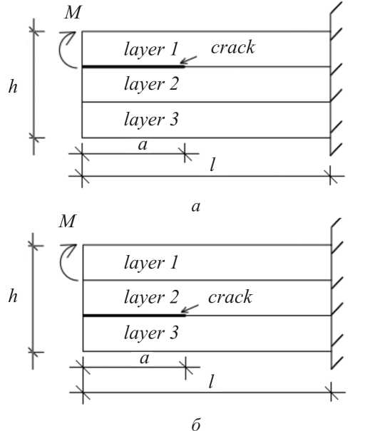
Fig. 3. Two three-layered beam structures ( a ) with delamination between layers 1 and 2 , and ( b ) with delamination between layers 2 and 3
-σ i 2
- L i t + f i 2
2 f i
L2 fσ i arcsin ii
L i
The strain energy in the un-cracked beam portion is found by replacing of m 1 , σϖ i , σϑ i , u 0 i and z 1 with m , σϖξ i , σϑξ i , u 0 ξ i and z 2 in (51). By combining of (48), (49), (50) and (51), one obtains
G =1 M (к b k 1
i = m 1 σ ϑ i
- K 2 ) - b ^ j u 0 idz 1
i = 1
σϖi i=m σϑξi
+ b E j u 0 ^ id z 2
i = 1 σϖξ i

where the curvatures, the stresses and the strain energy densities are found at x = a . The integration in (54) is carried-out by the MatLab computer program. The strain energy release rate is determined by (54) at various values of time. It should be noted that the strain energy release rates found by (54) are exact matches of these obtained by (46) which is a verification of the solutions.
Numerical results
This section deals with numerical results obtained by applying the solution of the strain energy release rate derived in
Two three-layered beam configurations are considered in order to investigate the influence of the delamination crack location along the beam thickness (Fig. 3). In the beam depicted in Fig. 3, a , the delamination is located between layers 1 and 2. A beam with delamination between layers 2 and 3 is also considered (Fig. 3, b ). The layers in the beams in Fig. 3 have identical thicknesses. The beams are clamped in their right-hand ends. It is assumed that b = 0.025 m, h = 0.012 m, l = 0.400 m, fi = 1 s and v = 0.9 ⋅ 10 -7 Nm/s.
First, the variation of the strain energy release rate with time is analyzed. The beam with delamination between layers 1 and 2 is considered. The results obtained are shown in Fig. 4 where the strain energy release rate is plotted against the non-dimensional time (the latter is obtained by using the formula tN = tEB α 1/ η B α 1). The curve in Fig. 4 indicates that the strain energy release rate increases with time.
This is due to two factors (increase of the external loading with time and the viscoelastic behaviour of the multilayered beam).
The variation of the non-dimensional strain energy release rate with E / E ratio for both three-layered beam B ω 1 B α 1
structures is shown in Fig. 5.
It is apparent from Fig. 5 that the strain energy release rate decreases with increasing of EB ω 1 / EB α 1 ratio.
It can be concluded also that the strain energy release rate for the beam with delamination between layers 1 and 2 is higher than that for the beam with delamination located between layers 2 and 3 (Fig. 5).
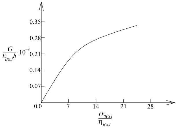
Fig. 4. Variation of the non-dimensional strain energy release rate with non-dimensional time
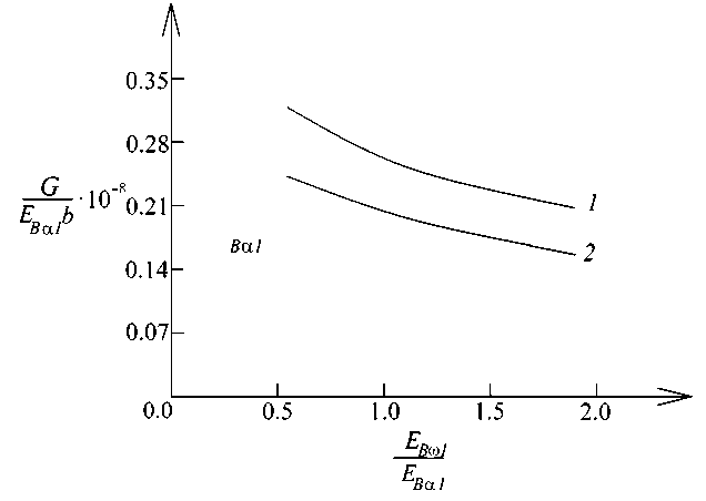
Fig. 5. Variation of the non-dimensional strain energy release rate with EB ω 1 / EB α 1 ratio (curve 1 – for the beam with delamination between layers 1 and 2, curve 2 – for the beam with delamination between layers 2 and 3)
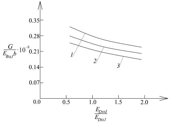
Fig. 6. Variation of the non-dimensional strain energy release rate with ED ω 1 / ED α 1 ratio (curve 1 – at a / l = 0.25 , curve 2 – at a / l = 0.50 and curve 3 – at a / l = 0.75 )
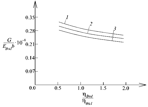
Fig. 7. Variation of the non-dimensional strain energy release rate with η B ω 1 / η B α 1 ratio (curve 1 – at η D ω 1/ η D α 1 = 0.5 , curve 2 – at η D ω 1/ η D α 1 = 1.5 and curve 3 – at η D ω 1/ η D α 1 = 2.5 )
Figure 6 shows the variation of the non-dimensional strain energy release rate with ED ω 1 / ED α 1 ratio for three a / l ratios.
The beam with delamination between layers 1 and 2 is analyzed.
From Fig. 6, it can be seen that the increase of the ED ω 1 / ED α 1 ratio leads to decrease of the strain energy release rate. It can also be seen that the strain energy release rate deceases with increasing of a / l ratio (Fig. 6).
The effects of η B ω 1 / η B α 1 and η D ω 1 / η D α 1 ratio on the strain energy release rate is illustrated in Fig. 7. It is observed that the strain energy release rate decreases with increasing of η B ω 1 / η B α 1 ratio (Fig. 7). The effect of η D ω 1 / η D α 1 ratio is identical.
The variation of the non-dimensional strain energy release rate with H ω 1/ H α 1 ratio for three values of the parameter v is displayed in Fig. 8.
The effect of H ω 1/ H α 1 ratio is to decrease of the strain energy release rate. From Fig. 8, it can be found also that the strain energy release rate increases with increasing of v .
The influences of L ω 1/ L α 1 and L α 2/ L α 1 ratios on the strain energy release rate are also studied. The strain energy release rate increases with the increase of these ratios as shown in Fig. 9.
Conclusion
A delamination analysis of a multilayered inhomogeneous beam by using a non-linear viscoelastic model is developed. A non-linear spring and a non-linear dashpot are added in a model that consists of two linear spring and two linear dashpots in order to describe the non-linear mechanical behaviour of the beam under consideration. The responses of the non-linear spring and dashpot are treated by applying non-linear constitutive relationships. The stressstrain-time constitutive law of the model is derived. The law is non-linear as a result of adding of non-linear spring and dashpot in the model. One of the important peculiarities of this constitutive law is that the stress can not be determined explicitly, in contrast to constitutive laws of linear viscoelastic models. The material properties which are involved in
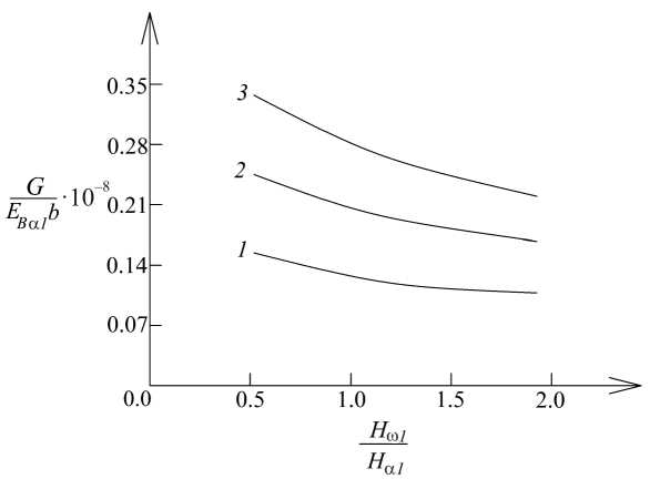
Fig. 8. Variation of the non-dimensional strain energy release rate with H ω 1/ H α 1 ratio (curve 1 – at v = 0.3 ⋅ 10 -7 Nm/s, curve 2 – at v = 0.6 ⋅ 10 -7 Nm/s and curve 3 – at v = 0.9 ⋅ 10 -7 Nm/s)
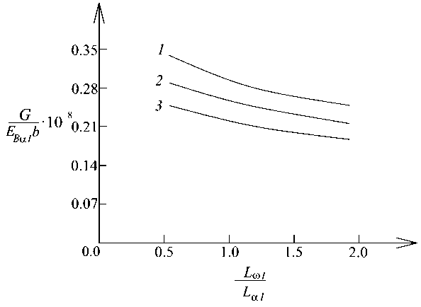
Fig. 9. Variation of the non-dimensional strain energy release rate with L ω 1/ L α 1 ratio (curve 1 – at L α 2/ L α 1 = 0.5 , curve 2 – at L α 2/ L α 1 = 1.0 and curve 3 – at L α 2/ L α 1 = 2.0 )
the constitutive law are continuous functions of the longitudinal coordinate since the layers exhibit continuous material inhomogeneity along the beam length. Solutions of the strain energy release rate for the delamination are obtained by using the complementary strain energy in the beam and by considering the balance of the energy. The two solutions generate identical results which prove their correctness. The solutions are time-dependent and take into account the nonlinear viscoelastic behaviour of the beam under external bending moment that is a linear function of time. The solutions are applied to obtain numerical results which clarify the influence of various factors on the strain energy release rate. The results obtained indicate that the strain energy release rate increases with time. The influence of EB ω 1 / EB α 1, ED ω 1 / ED α 1, η B ω 1 / η B α 1, η D ω 1 / η D α 1, H ω 1/ H α 1, L ω 1/ L α 1 and L α 2/ L α 1 ratios on the strain energy release rate is
References Utilization of viscoelatic models with non-linear springs and dashpots in delamination study of multilayered beams
- Li X.F., Peng X.L., Kang Y.A. Pressurized hollow spherical vessels with arbitrary radial nonhomogeneity. AIAA J., 2009, vol. 47, pp. 2262-2266.
- Tanigawa Y. Some basic thermoelastic problems for nonhomogeneous structural materials. Appl. Mech. Rev., 1995, vol. 48, pp. 287-300.
- Dai H.-L., Luo W.-F., Dai T. Multi-Field Coupling Static Bending of a Finite Length Inhomogeneous Double-Layered Structure With Inner Hollow Cylinder and Oute Shell. Appl. Math. Modell., 2016, vol. 40, pp. 6006-6025.
- Suresh S. Graded materials for resistance to contact deformation and damage. Science, 2001, vol. 292, pp. 2447-2451.
- Babushkin A.V., Sokolkin Y.V., Chekalkin A.A. Fatigue Resistance of Structurally Inhomogeneous Powdered Materials in a Complex Stress-Strain State. Mech Compos Mater, 2014, vol. 50, pp. 1-8.
- Paimushin V.N., Ivanov V.A., Lukankin S.A. et al. Shear and Flexural Buckling Modes of a Spherical Sandwich Shell in a Centrosymmetric Temperature Field Inhomogeneous across the Thickness. Mechanics of Composite Materials, 2004, vol. 40, pp. 309-330.
- Bochkareva S.A., Grishaeva N.Y., Lyukshin B.A. et al. A Unified Approach to Determining the Effective Physicomechanical Characteristics of Filled Polymer Composites Based on Variational Principles. Mech Compos Mater, 2019, vol. 54, pp. 775-788.
- Sheshenin S.V., Yikun D. Homogenization of Rubber-Cord Layers at Moderately Large Deformations. Mech Compos Mater, 2021, vol. 57, pp. 275-286.
- Malakhov A.V., Polilov A.N., Li D. Increasing the Bearing Capacity of Composite Plates in the Zone of Bolted Joints by Using Curvilinear Trajectories and a Variable Fiber Volume Fraction. Mech Compos Mater, 2021, vol. 57, pp. 287-300.
- Zarubin V.S., Savelyeva I.Y., Sergeeva E.S. Estimates for the Thermoelastic Properties of a Composite with Ellipsoidal Anisotropic Inclusions. Mech Compos Mater, 2019, vol. 55, pp. 513-524.
- Bakulin V.N., Boitsova D.A., Nedbai, A.Y. Parametric Resonance of a Three-Layered Cylindrical Composite Rib-Stiffened Shell. Mech Compos Mater, 2021, vol. 57, pp. 623-634.
- Fedotov A.F. Hybrid Model for Homogenization of the Elastoplastic Properties of Isotropic Matrix Composites. Mech Compos Mater, 2017, vol. 53, pp. 361-372.
- Zhang X., Hasebe N. Elasticity Solution for a Radially Nonhomogeneous Hollow Circular Cylinder. ASME J. Appl. Mech, 1999, vol. 66, pp. 598-606.
- Ter-Mkrtich'ian L.N. Some Problems in the Theory of Elasticity of Nonhomogeneous Elastic Media. J. Appl. Math. Mech, 1961, vol. 25, pp. 1667-1675.
- Plevako V.P. On the Theory of Elasticity of Inho-mogeneous Media. Journal of Applied Mathematics and Mechanics, 1971, vol. 35, pp. 806-813.
- Groves J., Wadley H. Fabrication of Functionally graded materials synthesis via low vacuum directed vapor deposition. Composites Part B: Engineering, 1997, vol. 28, pp. 57-69.
- Mortensen A,. Suresh S. Functionally graded metals and metal-ceramic composites: Part 1 Processing. International Materials Reviews, 1995, vol. 40, pp. 239-265.
- Robert C., Wetherhold Steven Seelman, Jianzhong Wang. The use of functionally graded materials to eliminate or control thermal deformation. Composites Science and Technology, 1996, vol. 56, pp. 1099-1104.
- Lee W. Y., Stinton D.P., Berndt C.C., Erdogan F., Yi-Der Lee, Mutasim Z. Concept of Functionally Graded Materials for Advanced Thermal Barrier Coating Applications. Journal of the American Ceramic Society, 1996, vol. 79, pp. 3003-3012.
- Pei Y.T., De Hosson J.Th.M Functionally graded materials produced by laser cladding. Acta Materialia, 2000, vol. 48, pp. 2617-2624.
- Aizikovich S.M., Vasil'ev A.S., Krenev L.I. et al. Contact problems for functionally graded materials of complicated structure. Mech Compos Mater, 2011, vol. 47, pp. 539-548.
- Bochkarev S.A., Lekomtsev S.V. Stability of Functionally Graded Circular Cylindrical Shells under Combined Loading. Mech Compos Mater, 2019, vol. 55, pp. 349-362.
- Bochkarev S.A., Lekomtsev S.V., Matveenko V.P. Hydro-thermoelastic Stability of Functionally Graded Circular Cylindrical Shells Containing a Fluid. Mech Compos Mater, 2016, vol. 52, pp. 507-520.
- Kieback B., Neubrand A., Riedel H. Processing techniques for functionally graded materials. Materials Science and Engineering: A, 2003, vol. 362 pp. 81-106.
- Chen Y., Lin X. Elastic analysis for thick cylinders and spherical pressure vessels made of functionally graded materials. Computational Materials Science, 2008, vol. 44, pp. 581-581.
- Dias C.M.R., Savastano Jr.H., John V.M. Exploring the potential of functionally graded materials concept for the development of fiber cement. Construction and Building Materials, 2010, vol. 24, pp. 140-146.
- Gandra J., Miranda R., Vila^a P., Velhinho A., Teixeira J.P. Functionally graded materials produced by friction stir processing. Journal of Materials Processing Technology, 2011, vol. 211, pp. 1659-1668.
- Zhang Y., Ming-jie Sun, Zhang D. Designing functionally graded materials with superior load-bearing properties. Acta Biomaterialia 2012, vol. 8, pp. 1101-1108.
- Tejaswini N., Babu R., Ram S. Functionally graded material: an overview. Int J Adv Eng Sci Technol 2013, vol. 4, pp. 183-188.
- Sola A., Bellucci D., Cannillo V. Functionally graded materials for orthopedic applications - an update on design and manufacturing. Biotechnology Advances, 2016, vol. 34, pp. 504-531.
- Minoo Naebe, Kamyar Shirvanimoghaddam. Functionally graded materials: A review of fabrication and properties. Applied materials today, 2016, vol. 5, pp. 223-245.
- Toudehdehghan J., Lim W., Foo1 K.E., Ma'arof M.I.N., Mathews J. A brief review of functionally graded materials. MATEC Web of Conferences, 2017, vol. 131, 03010.
- Nikbakht S., Kamarian S., Shakeri M. A review on optimization of composite structures Part II: Functionally graded materials. Composite Structures, 2019, vol. 214, pp. 83-102.
- El-Galy I.M., Saleh B.I., Ahmed M.H. Functionally graded materials classifications and development trends from industrial point of view. SN Appl. Sci., 2019, vol. 1, pp. 1378-1389.
- Rzhanitsyn A.R. Built-up Bars and Plates. Moscow, Stroyiizdat, 1986.
- Drory M., Thouless M., Evans A. On the decohesion of residually stressed thin films. Acta Metall, 1988, vol. 36, pp. 2019-2028.
- Townsend P., Barnet D., Brunner T. Elastic relationships in layered composite media with approximation for the case of thin films on a thick substrate. J Appl Phys, 1987, vol. 62, pp. 4438-4446.
- Freund L.B. The stress distribution and curvature of a general compositionally graded semiconductor layer. J. Cryst. Growth, 1995, vol. 132, pp. 341-344.
- Finot M., Suresh S. Small and large deformation of thick and thin-film multilayers: effect of layer geometry and compositonal gradients. J Mech Phys Solids, 1996, vol. 44, pp. 683-721.
- Kim J.S., Paik K.W., Oh S.H. The Multilayer-Modified Stoney's Formula for Laminated Polymer Composites on a Silicon Substrate. J. Appl. Phys., 1999, vol. 86, pp. 5474-5479.
- Yu J.-H, Guo S., Gillard, D.A. Bimaterial curvature measurements for CTE of adhesives: optimization and modelling. Journal of Adhesion Science and Technology, 2003, vol. 17, pp. 149-164.
- Markov I., Dinev D., Theoretical and experimental investigation of a beam strengthened by bonded composite strip. Reports of International Scientific Conference VSU'2005, 2005, pp. 123-131.
- Ivanov Ya., Stoyanov V. High Technologies and New Construction Materials in Civil Engineering. In: Education, Science, Innovations (Proc. 1st Int. Conf. of the European Polytechnical University, June 9-10, 2011, Pernik), 2011, pp. 161-169.
- Tahar H.D., Abderezak R., Rabia B. Flexural performance of wooden beams strengthened by composite plate. Structural Monitoring and Maintenance: An International Journal, 2020, vol. 7, pp. 233-259.
- Dolgov N.A. Determination of Stresses in a Two-Layer Coating. Strength of Materials, 2005, vol. 37, pp. 422-431.
- Dolgov N.A. Analytical Methods to Determine the Stress State in the Substrate-Coating System Under Mechanical Loads. Strength of Materials, 2016, vol. 48, pp. 658-667.
- Yang W., Shih C.F. Fracture along an interlayer. Int. J. Solids Structures, 1994, vol. 31, pp. 985-1002.
- Dowling N.E. Mechanical behaviour of materials. Person, 2013.
- Rizov V.I. Analysis of Two Lengthwise Cracks in a Viscoelastic Inhomogeneous Beam Structure. Engineering Transactions, 2020, vol. 68, pp. 397-415.
- Rizov V.I. Delamination analysis of multilayered beams exhibiting creep under torsion. Coupled Systems Mechanics, 2021, vol. 10, pp. 317-331.
- Lukash P. Fundamentals of non-linear structural mechanics. Moscow, Stroiizdat, 1978.
