Variability of circular depolarization ratio in radar sensing of the medium filled with hydrometeors

Author: Masalov Evgenii V., Krivin Nikolay N., Rudometova Anastasiia S.
Journal: Журнал Сибирского федерального университета. Серия: Техника и технологии @technologies-sfu
Article in issue: 8 т.12, 2019.
Free access
Circularly polarized waves are most sensitive to the influence of the propagation medium factors such as differential phase shift and differential attenuation. The reason of that is a feature of the wave polarization transformation. Such circumstances require consideration during designing radars working with circularly polarized waves. The aim of the study is to develop of approach for estimating the effect of the wave polarization transformation on a value of one of the most informative parameters based on the use of Jones vector component functional dependence on a polarization ellipse orientation angle and ellipticity angle. The task of this work is obtaining the analytical equation for the determination of that polarimetric radar informative parameter. As a result, the solution for the case of wave backscatter by the propagation medium was obtained when the medium basis orientation differs from the radar basis orientation. The estimation of the circular depolarization ratio providing the determination of regions with its raised value was obtained.
Circular polarization, differential attenuation, differential phase shift, polarization radar
Short address: https://sciup.org/146281410
IDR: 146281410 | UDC: 621.396.96 | DOI: 10.17516/1999-494X-0198
Изменчивость кругового деполяризационного отношения при дистанционном зондировании среды, заполненной гидрометеорами
Сигналы с круговой поляризацией в силу специфики трансформации поляризационной структуры сигнала наиболее сильно подвержены воздействию дифференциальных факторов (дифференциального фазового сдвига и дифференциального ослабления) среды распространения. Указанные обстоятельства требуют обязательного учета при проектировании радиолокационных систем, использующих данный вид поляризации. Целью данной работы является разработка подхода для оценки влияния трансформации поляризационной структуры на величину одного из наиболее характерных используемых в радиолокации информативных параметров, основанного на использовании функциональной зависимости компонент вектора Джонса от угла эллиптичности и угла наклона эллипса поляризации. Задача данной работы - получение расчетных соотношений для определения указанного выше информативного параметра поляризационной радиолокации. Получены расчетные соотношения для случая обратного рассеяния средой, ориентация поляризационного базиса которой отлична от ориентации измерительного базиса. Выявлены оценки указанного выше информативного параметра, позволяющие определить области с его повышенным значением.
Text of the scientific article Variability of circular depolarization ratio in radar sensing of the medium filled with hydrometeors
The prerequisite to the use for displaying and interpreting the measurements results of the circular depolarization ratio (CDR) [1] is pronounced dependence of the circularly polarized received signals amplitude on the shape of the water droplets. The ratio, as it shown in [2–4], is independent of the orientation of the hydrometeors and is less subject to the influence of third party noises. The higher intensity of the rain (in other words, the more water droplets shape differs from the spherical shape), the more differences of a signal received with right and left circular polarizations [5] in the case when the probe signal polarization has one of the pointed above circular polarization states.
Task statement
The character of the differences pointed above is the leading cause of the variability of the circular depolarization ratio CDR which determines in decibels (dB) on the base of amplitude measurements when the wave with the right circular polarization is transmitted, and the wave with the right circular polarization is received (e. g. ĖRR), or when the wave with the right circular polarization is transmitted, and the wave with the left circular polarization is received (e. g. Ė RL )
CDR(z) = 2Q.lg(|EiRR|/|EiRL|), (1)
where ĖRR is the amplitude of the signal transmitted and received with the right circular polarization (the first letter of the index means polarization of the transmitted signal, the second letter of the index means polarization of the received signal); ĖRL is the amplitude of the signal transmitted with the right circular polarization and received with the left circular polarization.
The differential attenuation ∆α [dB/km] and the differential phase shift ∆Φ [deg/km] concern to the main factors determining the transformation of the signal polarization structure in the process of its propagation in the medium filled with hydrometeors. These circumstances dictate the need for searching paths to evaluate the importance of the effect of these factors on the obtained measurement results and to determine the character of the variability of the measured parameter CDR.
The task of this work is obtaining the analytical solution for the evaluation of the circular depolarization ratio on the base of Jones vector component functional dependence on a polarization ellipse orientation angle β and ellipticity angle α.
Method of determining the circular depolarization ratio
According to the results of [6–8], the Jones vector of the radar signal in the eigen basis of the propagation medium can be represented using trigonometric functions of angles α and β as
E DUT^ = I cosP(z)cosa(z)+jsm P(z) sma (z) I I -sin p ( z) cos a ( z) + j cos ₽ ( z) sina ( z)|
where z is the length of the signal propagation path in a medium filled with hydrometeors. The ellipticity angle α and the orientation angle β of the polarization ellipse of the circular polarized signal propagating in the medium defines by results of [9] as
, , „ - . /2nO°-osaaz sin(AOz+0.5-n)\...
- O.Sarcsin( ),
'
where n = 1 2 3…
The complex amplitude of the received circularly polarized signal can then be determined from the following operator sequence:
E™(z)-[H-[R(e0)l-1-E°UT(z),(5)
where [TJ is the operator of the polarization converter of the received signal; [R(e 0 )] 1 — the operator of the transition from the medium basis to the measuring basis; β0 – the angle of orientation of the measuring basis relative to the medium basis.
For the case of receiving the signal with the right circular polarization [TJ defines as m - ^10 j (6)
For the case of receiving the signal with the left circular polarization [TJ defines as
[TJ - ^10 0^ (7)
The received right circularly polarized signal can then be found by performing multiplication of the matrixes as:
RR V2 *0 0 1 ls in Po
-sineoI I cos e(z) cos a(z) + j sin e(z) sina(z) I = coseo I" I -si n e (z) cos a(z) + j cos в ( z) sin a( z) I
1 j 2 (8)
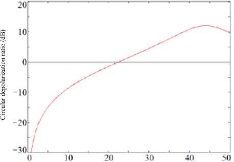
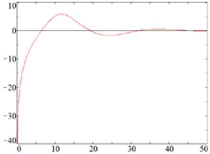
= ^40° e z cos a(z) + cos e . sin a • (cos во - j sin во). After the simple manipulations, we finally obtain: - !(=-₽..₽(•)), ERR®" ^4 )(cosa(z) + sina(z)). As can be seen from (9), the expression for the amplitude of the signal received with right circular polarization is 16Ia(z)| = ^(cosa^ + smatz)). The phase of the signal received with right circular polarization is фRR(z) 4 Po + P(z)- In the case of receiving a signal with left circular polarization, we have 6in(z1 = _Le-ji|1 j I |cos во RL •' IQ Ql IsinPo sin во I cospo I" • I cosP(z)cosa(z) + .sinP(z)sina(z) I. I -sin P(z) cos a(z) + j cos P(z) sin a(z) I By performing the transformation similar to the previous one, we obtain the expression for the received signal with left circular polarization: • IN - -j(”+3o + 3(z)) . Erl(z) = V5e V4 4cosa(z)-sina(z)). Then the amplitude of the signal defined in (13) will be |ERnl(z)| = -^(cosa(z) - sina(z)). The phase of the signal received with left circular polarization is = -(^o+№)). To obtain desired expression for the circular depolarization ratio, let us define its value at the output of the logarithmic receiver as CDR(a(z)) = 2Q.lg(|ERR(z)|/|ERL(z)|). After the substituting (10) and (14) expression (16) can be written as CDR(a(z)) = 20 • 1g fcos“(z) sin“(z)\ v ; cos«(z)+sin«(z)/ Results analysis Fig. 1-3 show the plots of the CDR as a function of the observation distance z calculated according to (17) for several values of the rain intensity. Differential attenuation Δα and differential phase shift Distance (km) Fig. 1. CDR as a function of observation distance z for the rain intensity R = 12.5 mm/h Distance (km) Fig. 2. CDR as a function of observation distance z for the rain intensity R = 50 mm/h Distance (km) Fig. 3. CDR as a function of observation distance z for the rain intensity R = 150 mm/h ΔΦ values measured for the three-centimeter distance signals have used in the calculations. For the different values of the rain intensity R, these values were [9]: (a) Δα = 0.02 dB/km, ΔΦ = 1 deg/km for R = 12.5 mm/h; (b) Δα = 0.1 dB/km, ΔΦ = 4 deg/km for R = 50 mm/h; (c) Δα = 0.8 dB/km, ΔΦ = 14 deg/km for R = 150 mm/h. The analysis of the calculated curves of the CDR (see Fig. 1-3) at short distances z (for the front boundary of the meteorological formation) shows a substantial difference in the ratio value which at z = 5 km is about 25 dB for R = 12.5 mm/h, 15 dB for R = 50 mm/h, 40 dB for R = 150 mm/h respectively. In this case, starting with the precipitates intensity of 50 mm/h, areas of positive values of the CDR evaluation appear. For R = 50 mm/h, the maximum of the CDR in the positive region is 12.5 dB, and for R = 150 mm/h is 6…7 dB. In the last two cases, CDR equals zero at a distance of 22.5 km (for R = 50 mm/h) and has four zero values at the distances of 6.45; 19.3; 32.15 and 45 km (for R = 150 mm/h). Conclusion The analytical solution for the evaluation of the circular depolarization ratio CDR on the base of Jones vector component functional dependence on a polarization ellipse orientation angle β(z) and ellipticity angle α(z) was obtained. As it seen from (17), the characteristic feature of CDR is its dependence only on the variability of the ellipticity angle α(z). In this case, the ratio is independent of the orientation angle β(z) changing. The magnitude of the circular depolarization ratio CDR as it follows from (3) and (17) depends on differential characteristics of propagation medium – differential attenuation Δα and differential phase shift ΔФ. The variability of the ratio has a pronounced character and substantial differences (up to 50 dB) at the short distances (z is about 12 km) from the front boundary of the meteorological formation. Established CDR sign change is an undoubted indication of high-intensity precipitates presence in the sensed meteorological formation. The procedure of high-intensity precipitation meteorological formations determining can be performed with the use of the algorithm (see above) for the CDR evaluating based on transmission and reception of signals with circular polarization (|Err| and |Erl|). In this case, the appearance of the positive ratio can indicate the meteorological formation with a high rain intensity.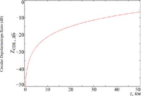
References Variability of circular depolarization ratio in radar sensing of the medium filled with hydrometeors
- Масалов Е.В., Татаринов В.Н. Поляризационные измерения в задачах радиолокационной метеорологии. Зарубежная радиоэлектроника, 1987, 4, 44-52
- Ryzhkov A., Zhang P., Cao Q., Matrosov S., Melnikov V., Knight M. Measurements of circular depolarization ratio with the radar with simultaneous transmission/reception. ERAD 2014 - The 8th European Conference on Radar in Meteorology and Hydrology, 2014 - Access: http://www.pa.op.dlr.de/erad2014/programme/ExtendedAbstracts/232_Ryzhkov.pdf.
- Nicolet M., Schnaiter M., Stetzer O. Circular depolarization ratios of single water droplets and finite ice circular cylinders: a modeling study. Atmospheric Chemistry Physics, 2012, 12, 4212-4213.
- Galletti M., Huang D., Kollias P. Zenith/Nadir pointing mm-wave radars: linear or circular polarization? IEEE Transactions on Geoscience and Remote Sensing. 2014, 52(1), 628-639.
- Galletti M., Huang D., Kollias P., Giangrande S.E. Towards a CDR-based rain rate estimation algorithm for zenith-pointing cloud radars at Ka band. ERAD 2012 - The 7th European Conference on Radar in Meteorology and Hydrology, 2012 - Access: http://www.meteo.fr/cic/meetings/2012/ERAD/extended_abs/CR_100_ext_abs.pdf.
- Jameson A.R., Dave J.H. An interpretation of circular polarization measurements affected by propagation differential phase shift. Journal of Atmospheric and Oceanic Technology, 1988, 5(6), 405-415.
- Родимов А.П., Поповский В.В., Дмитриев В.И. Особенности использования поляризационных параметров электромагнитных волн в системах связи миллиметрового диапазона. Зарубежная радиоэлектроника, 1980, 7, 25-37
- Татаринов В.Н., Лигхарт Л.П., Татаринов С.В. Введение в современную теорию поляризации радиолокационных сигналов. Поляризация плоских электромагнитных волн и её.преобразования. Под ред. В.Н. Татаринова. Томск: ТУСУР, 2012. Т. 1. 380 с.
- Масалов Е.В., Ещенко С.Ю. Влияние дифференциальных факторов среды распространения на поляризационные характеристики электромагнитной волны. Изв. высш. учеб. зав. Физика, 2012, 55(3), 28-33
