Verification of cloud based information integration architecture using colored petri nets

Author: Murale Narayanan, Aswani Kumar Cherukuri
Journal: International Journal of Computer Network and Information Security @ijcnis
Article in issue: 2 vol.10, 2018.
Free access
Healthcare applications, such as patient record, patient – doctor mapping service, various disease symptoms etc. The major challenges is processing and integrating the real time data. Following-up with analyzing the data would involve moving the data in Data Lake to a Cloud to known about the status of the patient and for tracking purpose. In this research, we recommend a cloud based information integration framework using Data Lake in Cloud. This work extends the information integration architecture by designing with Data Lake in Cloud, using mathematical model (Petri Net) to verify architecture. This approach has the ability to scale up and down in real time data, and leading to efficient way of using data resources in the Cloud.
Information, petrinet, Cloud, Healthcare, Information Integration
Short address: https://sciup.org/15015573
IDR: 15015573 | DOI: 10.5815/ijcnis.2018.02.01
Text of the scientific article Verification of cloud based information integration architecture using colored petri nets
-
I. Introduction
World Health Organization reports that 36 million of 57 million global deaths [2008] were due to Non transmissible diseases such as stroke, heart disease, cancer, chronic respiratory diseases and diabetes [1]. In India, 74.6% of deaths are due to primary diseases such as cardiovascular, respiratory, diarrheal, and perinatal, tuberculosis, senility, tumors, unintentional injuries and ill-defined conditioned diseases. While in public places people may face sudden illness such as heart attack, strokes, asthma attacks, fainting, vomiting, seizures, diabetic emergencies and other life threatening attacks. Either the public or the doctor in nearby hospital could not aid the suffered person immediately since they may not aware of the medical history of the affected person. If accurate, legible and updated medical records of the patients are not available, it is very difficult for the care providers (doctors) to decide on the treatment plan.
Generating blood test and other tests for identifying the disease will take some time and this delay may threaten the life of the patient. During this emergency period, providing medical history of the patient to the doctors is necessary. Unfortunately there is no other system exists in the world for providing this kind of information service during emergency period. Similarly a significant amount of people would like to pay more attention to their health to get precautionary health examination or to know about the similar patient’s medical records. Therefore, to achieve the demands of Suboptimal Health Status groups and senior citizens of the population, real - time health care services should be developed to help people to know about the precaution knowledge about the disease conveniently at home [5][6][7].
On the other hand, the huge amount of medical data both clinical and patient will need to satisfy the necessities of SHS groups and senior most people. However, the enormous amount of medical data as well as its several formats, pretense a challenge on-scale data management and efficient mining technologies, which is also known as “Big Data” issue [2]. Due to the salient features of cloud computing such as elastic storage computing, and service-oriented nature [6][8]. Cloud computing technologies have been widely researched and used in big data area [9][10]. Many healthcare services are migrating into the cloud environment. Instead of having many individually managed collections of medical records, we can combine them in the Data Lake. It is better to store data in this own format, when compared to Big data.
-
II. Literature Survey
-
A. Healthcare
Healthcare Information System was initiated and stretched from the hospital information system that discourses the health informatics issues. The main issue involves in shifting from paper to computer, and to store the data in the cloud. Patients, healthcare consumers, and doctors are involved more as a team from an outdated in or out-patient medication, to a broadly acceptable treatment whenever needed. Such a shift needs a significant powerful interconnected networking with a highly expandable computing node which will help in computing the framework and processing big-data.
These days even pets have a hip replacement surgery; it’s very hard to think not in spending every single penny to extend Grandma’s life—or our own. In the country like U.S. health care is something we choose to spend our money on. We are wealthy or not, nobody wants treatments ineffectively.
Nobody wants to wait for hope that their own biology genes are similar to some patient. None wants a “winners take all” system. In this eventually patient will be the loser, they pay for almost all procedures whether it’s helpful or necessary. Likewise Wanamaker with his advertisements, we would like to know what works for the patient and pay for whatever test they take. We need smarter systems, which help to design an effective treatment through our individual doctors; where treatments are administered in hospitals is used effectively; and where patients can pay for their outcomes and not for unnecessary procedures. We are on the edge of that new system. DNA sequencing in doctor’s office, which is very cheap and huge inexpensive computing technology, that helps in availability of EHRs to study whether the treatments are given effectively even after the FDA trials, and to get better techniques for analyzing the data.
-
B. Introduction of Data Lake (Big Data)
Data Lake is a storing technique for storing a very large amount of raw data in the format, where data is extracted. While a data warehouse helps in storing the data in files or folders, a data lake uses a different architecture in storing data. Individually data in the lake is given a unique ids and tagging with a usual set of extended metadata tags. When a business query arises, the query is sent into Data Lake to get relevant data, and that smaller data set can be analyzed.
Table 1. Data Warehouse vs Data Lake
|
Data Warehouse |
Vs |
DATA LAKE |
|
Structured, processed |
DATA |
Structured/ semi- structured/ unstructured, raw |
|
Schema on write |
PROCESSING |
Schema-on-road |
|
Expensive for large data volumes |
STORAGE |
Designed for lowcost-storage |
|
Less agile, fixed configuration |
AGILITY |
High agile, configure and reconfigure as needed |
|
Mature |
SECURITY |
Maturing |
|
Business professionals |
USERS |
Data scientists et. al |
-
C. Big Data studies in Health Sciences:
Big Data technologies may have various successful applications in biomedicine, particularly in healthcare sciences. For example, data from the search engines and social networks which will help to gather people’s reactions and observe the conditions of epidemic diseases. It will be a real-time analysis world-wide and helps to know about it much quicker than the official channels, such as CDC (Centers for Disease Control) and WHO (World Health Organization). Several cases studies will be elaborated in following paragraphs. Recommendation system in health care recently, many researchers applied recommendation techniques to health information systems [5–7]. [16] Proposed a nursing care plan recommendation system to deliver clinical decision support for nursing education, and about clinical quality control. It serves as a supplement to existing practice guidelines. [17] Proposed a reliable privacy-preserved medical recommendation system. In this medical system, the patients could be able to contribute to their secured ratings about the physicians on their different health conditions based on their satisfactions.
-
III. Problem Definition
-
A. Background:
Gaining visibility into all the information produced within hospitals or scan centers etc, putting it in context and driving effective action based on a complete picture of the latest patient’s information are great challenges healthcare today. Clearly, what is needed is not just a new set of integration technology approaches, but also a fundamental change in the way healthcare information systems and processes to handle integration requirements.
It has been realized that changing integration requirements are met through service oriented architecture. This shift in SOA would enable business to form information service that provides a easy, integrated view of real-time, quality information about a specific patient.
-
B. Motivation:
Few characteristics that have been found out as research problems which leads to the necessity of information integration in health care are:
-
• The information integration model or frameworks designed are not suitable to be adapted in healthcare environment where the model could be reused. But in real, integrated information needed to be part of every infrastructure and needs to be matured to a point where it is necessary for granting and diminishes into the related like of other ubiquitous technologies.
-
• There is no proper flow affecting the execution of components of information integration system. Which lack suitable process chain and usage of tools?
-
• Integration has been realized through service oriented architecture and not through cloud, which inherits SOA concepts in it.
-
C. Problem Statement:
As per the architecture information integration will not stop in providing a single view of the various information sources but provides a series of sub process that aligns with the context and motive behind Information integration as a service.
Input: The request from a user, is sent to request handling, and it is requests are interpreted with respect to domain ontology, which analyzes the request for the need of different information.
Process: Information Retrieval from all associated data and it is modeled into information with various semantics, ontology, and rules for data sources, integration of the various information.
Output: Analyze the requestor information from security aspects, accessibility rights, structuring of the integrated result with respect to the requestor.
Hence the Problem statement is:
“ To design a layered architecture for Information integration by adopting cloud and Data Lake into it, this helps to deliver integrated information as a service”.
There are very few models that explain the need of information integration in health care industry. This architecture aims to give cloud based information integration which is suitable for any integration problem.
The main objective of the proposed Cloud based Information Integration Health Care using Data Lake is to provide various health care services like:
-
- Health Record Service (HRS),
-
- Disease Prediction Service,
-
- Patient-Doctor Mapping Service (MS),
-
- First Aid Service (FAS)
-
- Hospital Tracking Service (HTS),
-
- Disease Alert Service (DAS).
-
D. Research Approach:
The problem identified enforces the need for an information integration architecture that gives a comprehensive picture of its components and process flow for effective result. To build a view from existing recent architecture that suits the best challenging requirements has been chosen. To verify the proposed architecture Colored Petri Nets is found to simple, automated and graphical tool which exhibit various states and transitions.
The architecture is to be implemented for suitable healthcare application. The research approach adopted in shown below:
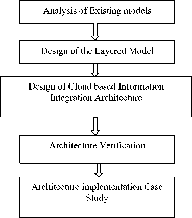
Fig.1. Research Approach
-
E. Findings:
Another domain that depends highly on information integration is Health care industry [10][11]. The information integration solutions offered by these works specific their requirements and sources. Hence it is clear that no common architecture exist.
-
IV. IIAAS ( Information Integration as a Service) Architecture
-
A. Introduction:
Efficient resolutions and planning depends highly on availability of information. The information has to be consistent and could be realized through loose coupling of data and applications. Cloud services changes the technique of thoughts about everything in a company’s IT organization into a new one, including the data. It starts with accomplishing data consistency. It attains data consistency by removing the tight coupling that exists between the business applications and its data. This is made to happen to make sure that data is used independent of its current implementation. The Primary aim of this research work is to offer integrated information as a service.
-
B. Architectural Model
Framework for Cloud based Information Integration using Data Lake:
The proposed information integration health care service system is designed for patients and doctors for self-caring, analyzing the diseases with related historical medical records. Examining the related medical records from the huge incremental amount of medical records requires an on-demand storage and scalability to manage the peak hour access to the health care diagnosis service. The prominent characteristics of cloud computing are real time services; and its ability to increase the scalability in computing, a cloud-based architecture is proposed to implement the Information Integration framework in information intelligent Health Care system
Health Care Service. The Fig. 1 shows the cloud based
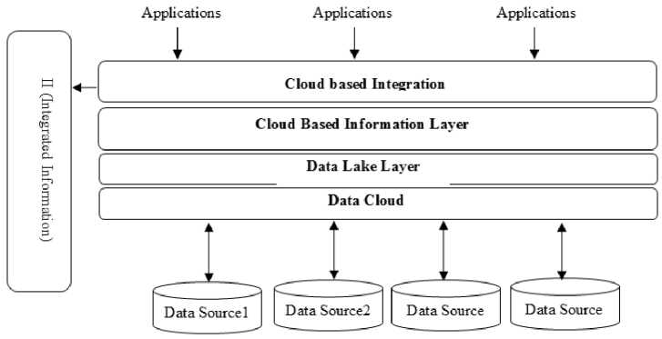
Fig.2. Cloud Based Information Integration Architecture
Table 2. Cloud Components and Applications
|
Descriptions |
Details |
|
Data Source: |
Hospital data, private clinical, health monitoring agents etc. |
|
Data Cloud: |
Manages the assorted data. |
|
Data Lake Layer: |
Handles these assorted data |
|
Cloud Based Information Layer: |
Get these various data and model them to information |
|
Cloud Based Integration Layer: |
Patient’s various information is integrated in these layers. |
|
Applications: |
Health Care Applications |
|
II – Integrated Information |
Integrated information of an user from different sources, which may be located at various geographical location |
To speed up medical record retrieval for health care services, information integration technique is adopted and data lake model is used for offline data storage and to manage the assorted data.
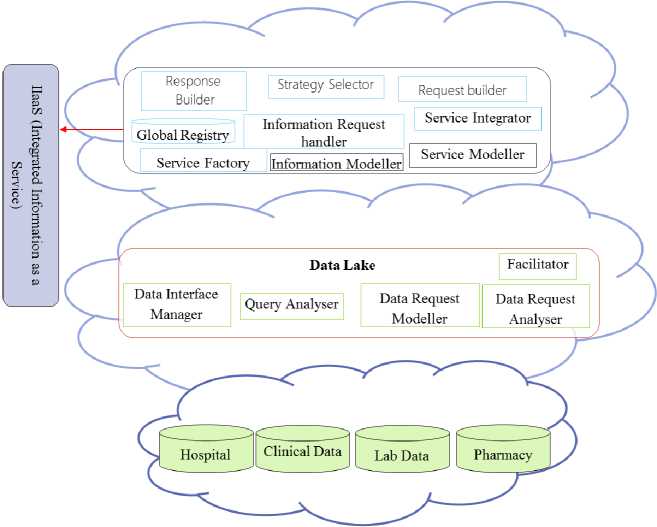
Fig.3. Cloud Based Frame Workflow for Intelligent Mobile Health Care Services
-
C. Cloud Based Information Integration Architecture
This data from various data sources like Hospital data, private clinical, health monitoring agents etc is collected and managed in Data Cloud. Data cloud collects data from various sources and manages them.
-
❖ These assorted data is handled by Data Lake. Data Lakes focuses on storing the data from distinct sources and ignoring its usage, governed, defined and secured by an organization’s. The data lake concept handles two major problems.
o First, it resolves information silos. Than having many independently managed groups of data, you can associate these sources in the Data Lake. The consolidation of theoretical results increased in information use and sharing, while cutting its costs in server and its license.
o Second, Data Lake theoretically tackles problems related to big data initiatives. The big data project requires a huge amount of varied information. The information varies in a way that we don’t know what it is the data, when we receive it; and constraining it in something as structured as a DW or RDBMS for future analysis.
-
❖ Information and integration layer collects the requested data and received as a response from the Data Lake Layer. The data is converted to information and modeled along with various business rules.
-
❖ The requested information is obtained as information service after complex processing and the information from various data sources is integrated in integration layer.
-
D. Methodology:
In general, a patient’s disease will be typically found based on his/her symptoms, as well as his/her age and gender. Patients with similar symptom, age and gender tend to be infected with similar kind of diseases. Based on the observation, patient’s symptoms, gender and age are necessary to map with the similar medical record retrieval from large medical records. In this case Medical record plays a vital role.
This is achieved by recommending [12] the necessary medical details to the patient at the right time. A recommendation has been developed to recommend the appropriate hospitals, labs and medic to the patients based on their historical records and their financial status.
Usually, in clinical activity, an electronic medical record is either an XML file consisting of tag-value pairs stored in file systems, or a relational record stored in relational databases.
Table 3. Data Records
|
Details |
Description |
|
Medical Rerecord |
An Electronic Medical Record is defined by a triple tuple: EMR = (patient data, patient profile, and clinical data) (Zhang et al., 2013; Li et al., 2010). |
|
Patient Data |
Patient data consists of basic information of a patient, such as patient’s name, gender, and date of birth, etc.; |
|
Patient Profile |
Patient profile usually includes summary of a patient’s medical history, including disease history, surgery history, transfusion history, as well as allergy history, to name a few; |
|
Clinical Data |
Clinical data stores detailed clinical informatics, including symptom set, patient complaint, present history, diagnosis result, treatments, and so on, associated with a patient’s each visit to a healthcare practitioner |
-
V. Applying Mathematical Model using Coloured Petri Nets
-
A. Introducing Petri Net:
A Petrinet is used for mathematical modeling languages for the portrayal of distributed systems.
-
B. Colored Petri Net (CPN)
Coloured Petri Nets (CP-nets or CPNs) is used to visualize the various models for building of distributed systems and analyzing their various properties for the process flow. CP-nets is a discrete modelling language used to design the architecture with linking the capabilities of high-level programming language. Petri nets may lay the establishment of the visual note and the basic primitives for modelling communication, concurrency and synchronization. The CPN is based on the efficient programming language. Standard ML, which provides the primitives of data types and its definition, for describing its data manipulation, and creating compact and parameter based models. CPN is well-suited for modelling and analyzing huge and complex systems flow or architecture for various reasons: they have an in-built graphical representation; which are executable in nature; hierarchical models can be built and it is possible to model and calculate the time used by different activities within a system, which helps in maturing and well-tested tools exists for designing, creating, simulating, and analyzing using Colored Petri net models
-
C. Building Scenario for CPN Model:
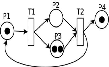
The CPN Model for has to be designed in such a way to incorporate the components of the architecture as static and dynamic elements. The rectangle boxes indicate the dynamic elements and the oval represent the static elements which just hold the value or data. The process of any scenario would follow all the components; thereby verify the functionalities of the elements.
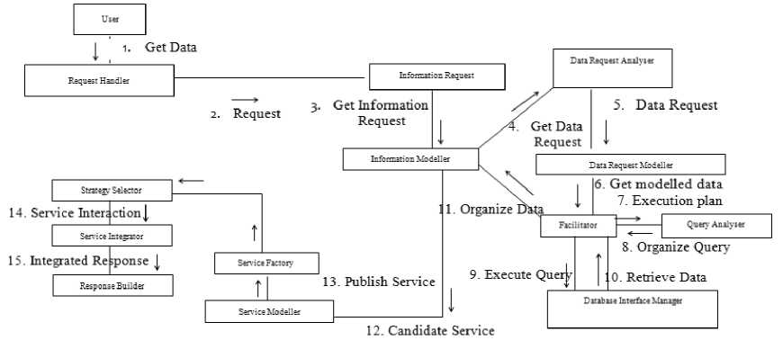
Fig.4. Collaboration Diagram
The request is handled to obtain the associated information and this information is handled to acquire the associated data from data sources through the facilitator transition. The information is organized or transformed or structured through modeling and the respective service is created and the response is build and delivered. Thus the general structure of CPN model to be designed and simulated through CPN tool is explained.
-
D. Formal Definition of CPN for Architecture
CPN definition is autonomous of the tangible inscription, and which means that the programming languages other than CPN can be used. In formal definition of CP-nets, it is assumed that the programming language chosen provides a constructive way of defining various data types and declaring its variables. Furthermore, it is presumed that the programming language has a view of various terminologies that makes it possible to talk about the various type of an expression and its result of evaluating an expression when the variables are certain to the values of the proper data types. It has three steps
-
• Multi sets
-
• Structuring the Nets and its inscriptions, i.e., the syntax of CPN models.
-
• Outlines the occurrence and enabling of phases, i.e., the semantics of CPN models.
The main objective is to define formal definition of the non-hierarchical CPN model by defining the attributes used in the model [15]
-
E. Formal Definition of Colored Petri Net
A Colored Petri Net is a nine-tuple = ( p,-rA£,n,5Aa,0 ), where
-
• p is defined as finite set of States.
-
• т is defined as finite set of conversion т such that pnт=ф
-
• A cp x TUT x p is defined as set of directed lines.
-
• ^ is defined as finite set of non-empty data sets.
-
• л is defined as finite set of keyed identifiers such that T[i ]e^ for all identifiers 1 ел .
-
• 5:p^^ is defined as data set function that contains a
data set to each State.
-
• Q: T^ Fi is a function that contains a condition for every conversion т. such that T[Q(r ) ]=bool
-
• а: Д ^ Fi is a line of expression function which assigns a line expression to each line Д such that T[ а( Д)]= 5(p)M S,
where p is the state connected to the line 5 .
-
• в: p^ F ф is a boot function that assigns a boot expression to every place р such that T[ 0(p )]= 5(p)M S.The above given formal
definition about the syntax of CPN vary from the formal definition in a slight ways. In CPN, parallel lines are not directly allowed in the definition of a CPN, and it has been improved to contain a set of variables V. The change has to be included to build the definition which concurs with how ease the user develops a CPN model using the tool. Users are allowed to declare variables in such a way that they can emerge as open variables in the guards and line expressions.
-
F. Formal Definition of CPN Model for the
Architecture
Different functions used in the definition of the CPN model are:
-
• Ide[€] which contains the identifier list used in the CPN model
-
• 5 ( p ) it defines the possible data set to be used in
each state.
-
• Q (t) condition function that contains a condition to each conversion
-
• a (a) list of identifier used by different state and conversion.
p = {initial Detail, request handler, information request, data request modeler, Query analyzer, DB, Service factory, strategy selector, Response builder}
This represents the set of all states in the CPN model where the states are used to hold the different values like request, information pertaining to the request, structured request, candidate service and format of response obtained from the components in the layers of the architecture.
t = {Service Request handler, information modeller, facilitator, Service modeller, service manager, service integrator}
This represents the set of all states in the CPN model where the transition are used to transform the different values like request, models the users information request, facilitates between the federated data sources to get the data for users request, creates a candidate service and it is changed to a specific service template and various response are integrated and transformed as a response from the components in the layers of the architecture.
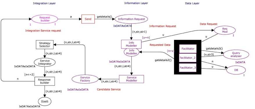
Fig.5. CPN Model
In CPN p and t should be two disjoint entities such as p. Directed lines A that connects conversion and states are classified into two sets of pairs where the source is denoted by the first component and destination is denoted by the second component. To confirm that a line either connect a state with a conversion or a conversion with a state, Δ of CPN model is defined as below:
Δ={(Request handler, Service request handler), (Service request handler, Information request handler), (Information request handler, Information modeller), (Information modeller, Data request modeller), (data request modeller, facilitator), (facilitator, Query Analyser), (Query Analyser, facilitator), (facilitator, DB), (DB, facilitator),(facilitator, information modeller), (information modeller, service modeller), (service modeller, service factory), (service factory, service manager), (service manager, strategy facilitator), (strategy selector, service integrator), (service integrator, response builder)}
Net Inscription i.e. the line expressions, condition, data sets, and boot markings. T[i] and the inscription language provides the set of expressions that are signified by F, the type of an expression €gF, i.e., after evaluating € which defines the type of values. Ide[€] is used to denotes a set of free identifier in an expression € and T[n] is used to denote the type of a identifier n. The following free identifiers are used in the line expressions of the CPN model for SOII architecture as
Г to
I (n, Str, strl)
Ide[€] = < (u)
(v, str3)
V(n, str, I, str4)
In CPN model for SOII architecture is used to denote the set of data sets and it is represented as
^ = {I, I x DATA, I x DATA x DATA, I x DATA x I x DATA}
Set of identifier are denoted by n. These identifier are required to have a specific type which belongs to £. Let £tn be a subdivision to the set of identifier n. €gF be the set of terms where F£ can be denoted as Ide[€]c£ The following identifiers for the CPN model for SOII architecture are represented as п = {a:I, str:Data, str:IxData, n:IxData, str:DataxI xj, n: Data×I ×I, u:Data×I ×I, str1:Data×Data, str2: Data×Data, str1: Data×Data×I, str2: Data×Data×I, n:Data×Data×I, P5: I×I×Data, P4: I×I×Data, str3: I×I×Data,}
In correspondence to the identifier declared in CPN model for SOII architecture, dataset 5 ( p ) belonging to the set of types C is assigned to each state p by the data set function 5 : p^c . The data set function of the CPN model for SOII architecture is represented as:
5 ( p )
r I
I x DATA x DATA
I x DATA
= I x DATA x I x DATA
if p = start if p = information request if p = Query Analyser if p E {information modeller, > service factory, strategy selector, Response builder}
Condition =
u = n 1 . n < 2 j
An line expression a (a) is assigned to each line a, by the line expression function а: Д ^ Fi. It is necessary that the free identifier of a (a) line a subset of п, i.e., that a (a) e Fi.
For a line ( p , т)e Д , connecting a state pep with a conversion TeT , if is necessary that the type of the line expression can be different combination of data set 5 ( p ) of the state p , i.e. T[ a(p , T) ]= 5(p)M S.
Similarly, it is required that T[a(T,p)]= 5(p)MS for a line (т,p)eД. The line expression is defined as a (a)
(a), if a = {get initial detail,
Request Handler}
(n,str,str1), if a= {service request handler, information request handler, information modeller}
(v,str3), if a = {query analyzer, facilitator}
(n,str,l,str4) if a= {service modeler, service factory, service manager, strategy selector, service integrator, Response Builder}
Thus the formal representation through Identifier, variables, data set, line expressions, conditions are defined to formally specify the CPN.
-
G. Verification Properties of IIaaS CPN Model:
The necessary assets of CPN model are identified and formal techniques are used to verify them by using state space analysis. Three key properties are defined for to ensure the request are aligned with relevance to context and the needed information are obtained and integrated as per the request, to complete the process without any deadlock. The properties chosen to verify the are
P0 (symmetry): different scenario and its I/O are unordered
This property can be verified by different possible information integration scenarios and checked whether the simulation of the architecture works correctly.
P1 (no deadlock): the model may always process different incoming context requests
This property can be verified by checking whether the CPN works for the number of information required and integrated without indefinite looping and as well as by observing the liveliness property which give the dead marking as result of the model.
P2 (fairness): every place and transit of CPN model is detected and processed
This property can be verified by observing the fairness property of state space analysis report. It should contain no infinity sequence which means that the model works completely as well as correctly by processing the functions exposed in transitions, placing the outcome in places. P0, P1, P2 are difficult to verify, despite it can be achieved through the execution of number of test cases and also to examine all possible execution orders.
-
H. Verification of Architecture Through the Case Study
The CPN model that has been designed has to be simulated to analyzed the behavioral aspects of each component expressed as transitions and see whether it produces the expected output. Hence sample values with respect to health record information integration is considered and shown below in the table. The values state a sample data for information integration.
Table 4. Outcome of different Transitions for Health Record Information Integration
|
SL .No. |
Component |
Input |
Output |
|
1 |
Patient Input in hospital 1 |
(111, “Joseph”, “hospital 1”, “hospital 2”) |
|
|
2 |
Data Request from hospital 1 |
(“Joseph”, “CIR from hospital 1”) |
|
|
3 |
Requested Data from hospital 1 (input to hospital 2) |
(111, “Joseph”, 1234,” hospital 2”) |
|
|
4 |
Data Request from hospital 2 |
(1234, “Check whether this ID Exists in hospital 2”) |
|
|
5 |
Requested data from hospital 2 |
(222, “Joseph”, 1234) |
|
|
6 |
OTP |
Once the record matches in hospital 2, OTP is initiated |
9999694 |
|
7 |
Response |
(222, “Joseph”, 1234, 9999694) |
Inputs are given as shown below:
-
- Start 1`(111,"Joseph","hospital 1","hospital 2")
-
- Data Request from hospital 1 1`("Joseph", "CIR from hospital 1")
-
- Requested Data from hospital 1
1`(111,"Joseph",1234,"hospital 2")
-
- Data Request from hospital 2 1`(1234,"Check
whether this ID exists in hospital 2")
-
- Requested Data from hospital 2
1`(222,"Joseph",1234)
-
- OTP generates random number using normal distribution.
The definitions are split into three parts, as it goes to two different hospitals and OTP generation. These are the data handled at one hospital (hospital 1)
hospital 1, Ide[€] =
{ (a)—> (Alex)
(n, str, str1) —> (111, Alex, hospital 1,hospital 2)
(u)—> (111) S—
(str2, str3) —> (Alex, CIR Record from hospital 1)
(n, str, l, str4)—> (111, Alex, 1234, hospital 2)
Once this data is fetched from one hospital, it goes to other hospital to verify the customer. Once Patient is verified, the hospital initiated for OTP generation.
hospital 2, Ide[€] =
( (u)-> (1234)
I (v,str3)—>(1234, Checks whetherI
| customer exists in hospital 2)[
I (n,str,l)—> (222,Alex, 1234)
( (j)-> (1234)[
OTP Generation, Ide[€] = < (j@ + pt)—> 1234@9999694>
( (u)-> 9999694J
-
I. Verification of three key properties of health record Information Integration
The CPN accepts User Request and works with other hospital to get the patient details form other hospitals as shown in figure 6. With these data sets, the CPN has to be simulated with finite number of executions for which verifying scenarios where selected and simulated based on this simulation the verification properties are stated below.
P0: Patient record environment consist of a patient request to access his other hospital account from other hospital. These are combined in different possible combination to get the user hospital accounts from other hospital.
P1: This property shown in figure verifies that whether it always processes with different types of different user’s requests. It is verified that if another request is given to a hospital the architecture processed the request successfully
|
Liveliness Properties |
|
|
Dead Markings: All |
|
|
Dead Transition Instances: |
All |
|
Live Transition Instances: |
None |
Fig.6. Liveliness properties of Health Record Information Integration CPN Model
P2: The fairness property “no infinite occurrence sequence” shown in figure 5.8 that all transitions in the net terminate and thereby it indicates that the model works correctly and completely without any deadlock.
Fairness Properties ---------------------------------------------
No infinite occurrence sequences.
-
Fig.7. Liveliness properties of Health Record Information Integration CPN Model
Though P0 the CPN model has been executed three times to retrieve customer information from hospital 1, with hospital 1 as input the customer information from hospital 2 is obtained for validating the patient. This is followed by OTP generation, hence information is obtained and integrated for varying scenarios. P1 verifies the liveliness properties indicating that there exists no deadlocks in the model and P2 verifies that the model works for finite sequences and no infinite occurrences.
The model that has been designed needs to verified and evaluated to prove its completeness and working state. Petri nets are one formal method that has a graphical representation and can also be used as a simulator to verify a model or architecture. The CPN model is designed and verified for the proposed architecture for a health care scenario.
-
VI. Conclusion
Cloud based Information integration has been brought out complete architectures, methods, frameworks etc., as discussed in literature study but many challenges still persist. Information integration should be enabled to provide results to produce needed information in the correct form. It would allow them to achieve effective and efficient in taking decision or any significant purpose. This has been huge motive for this research and architecture is designed to give a clear picture without comprising in any aspects of information integration in healthcare. The cloud based architecture and its components is explained, along with the Petri Net (Applying Mathematical Model) based verification for health record information integration in health care domain.
References Verification of cloud based information integration architecture using colored petri nets
- Canny, J., Zhao, H., 2013. Big data analytics with small footprint: squaring the cloud In: Proceedings of the 19th ACM SIGKDD International Conference on Knowledge Discovery and Data Mining. ACM, pp. 95–103.
- Chaudhuri, S., 2012. What next?: a half-dozen data management research goals for big data and the cloud. In: Proceedings of the 31st Symposium on Principles of Database Systems. ACM, pp. 1–4.
- Ekanayake, J., Gunarathne, T., Qiu, J., 2011. Cloud technologies for bioinformatics applications. IEEE Trans. Parallel Distributed Syst. 22 (6), 998–1011.
- Ochoa, X., Duval, E., 2008. Relevance ranking metrics for learning objects. IEEE Trans. Learn. Technol. 1 (1), 34–48.
- Rashidi, P., Cook, D.J., 2009. Keeping the resident in the loop: adapting the smart home to the user. IEEE Trans. Syst. Man Cybern. Part A: Syst. Hum. 39 (5), 949–959.
- Shang, W., Jiang, Z., Hemmati, H., Adams, B., Hassan, A.E., Martin, P., 2013. Assisting developers of big data analytics applications when deploying on hadoop clouds. In: Proceedings of the 2013 International Conference on Software Engineering. IEEE, pp. 402–411.
- Zhang, Z., Wang, B., Ahmed, F., Zhao, R., Viccellio, A., Mueller, K., 2013. The five WS for information visualization with application to healthcare informatics. IEEE Trans. Visual. Comput. Graph. 19 (11), 1895–1910.
- Punitha Devi C, Prasanna Venkatesan V, Diwahar S, Shanmugasundaram S, “A Model for Information Integration Using Service Oriented Architecture”, I.J. Information Engineering and Electronic Business, 2014, 3, 34-43.
- Punitha Devi C, Prasanna Venkatesan V, Diwahar S, Shanmugasundaram S, “Design of Information Integration Architecture using SOA”, International Journal of Computer Applications (0975 – 8887) Volume 93 – No. 18, May 2014.
- Petri Net information and image retrieved on from: https://en.wikipedia.org/wiki/Petri_net
- Mukesh Mohania and Manish Bhide,”New trends in information integration”, IBM research Lab, 2007.
- N.W. Paton, C.A. Goble, S. Bechhofer, “Knowledge based information integration systems”, Elsevier Information and Software Technology, Vol 42 pp. 299–312, 2000.
- Nicola Leone, Thomas Eiter, Riccardo Rosati, Edyta Kalka, “The INFOMIX System for Advanced Integration of Incomplete and Inconsistent Data”, ACM, SIGMOD ’05, Maryland USA, 1-59593-060-4, 2005.
- Noel Yuhanna and Mike Gilpin, Information Fabric 3.0, Forrester Report, 2013.
- Oliver M. Duschka, Michael R. Genesereth “Infomaster- An Information Integration Tool”, International Workshop on Intelligent Integration, Friedurg, Germany, 1997.
- Patrick C.K. Hung, Dickson K.V.Chiu, “Devolping Workflow-based Information Integration with Exception Support in a Web Services Environment”, IEEE, Proceedings of the 37th Hawaii International Conference on System Sciences, 2004.
- Philip A. Bernstein, Laura Haas, “Information Integration in the Enterprise”, Communications of the ACM, Vol 51 No. 9, September 2008.
- R.H. Bayardo et al., “InfoSleuth: Agent-based semantic integration of information in open and dynamic environments”, Proceedings of the ACM SIGMOD, pp. 195–206, 1997.
- Shuwang Ke, Jitao Fang, Xiangqian Ding, Shusong Yu, Dan Li, “ The Design and Development of Shop-level Information Integration System”, IEEE, International Conference on Electrical and Control Engineering, 978-0-7695-4031-3, 2010.
- Song Xiao, Zhang Lin, Yu Peng-fei, “Semantic SOA- Based Enterprise Information System Integration Technology”, International Conference on Smart Manufacturing Application, April. 9-11, Korea , 2008
- Wang Zenglei, Zhang Kaixing, “An Enterprise Information Integration Architecture Based on Semantic and Grid”, IEEE, 978-1-4244-5540-9, 2010. www.ibm.com.db2.ii.doc
- X.Y. Li, Y. Qian, “A Web service Based Enterprise Information Integration Model”, IEEE, Proceedings of 4th International Conference on Computer Science and Education, 978-1-4244-3251-0, 2009.
- Xiangyu Li, “An Integration Framework for Information System based on Web Service”, IEEE, 978-1-4244- 5265-1, 2010.
- Ya.Li, Hairui. Wang Lin.Jin, Yuping.Liu, “A Multi Agent Framework for Enterprise Information Integration”, IEEE, International Conference on Measuring Technology and Mechatronics Automation, 978-07695-3962-1, 2010.
- Yannis Dimopoulos and Antonis Kakas, Information integration and computational logic, Special Issue on the Future Technological Roadmap of Compulog-net, (URL: http://www.compulog.org/net/Forum/Supportdocs.html.)
- Yong-Gang Gong, Xin Chen, “Healthcare Information Integration and Shared Platform Based on Service-Oriented Architectures”, IEEE, 2nd International Conference on Signal Processing Systems (ICSPS), 978-1-4244-6893, 2010.
- Zhang Zhenhai, Wang Xiaoming, Zhang Yanpeng, Study on Service-oriented Framework of Information Integration of Safety and Security for High-speed Railway, International Conference on Information, Networking and Automation (ICINA), 2010.
